Transcription
Remediation of Progressive Slope FailureBryan Erickson, MBA (Corresponding Author)Fenton Rigging & Contracting2150 Langdon Farm Rd.Cincinnati, OH 45237berickson@fenton1898.com(513)-758-1278Nate Landsperger, PEWood3800 Ezell Rd, Suite 100,Nashville, TN tt Schmidt, EITNicholson Construction4124 Douglas Ave., Kalamazoo, MI 49008scott.schmidt@nicholsonconstruction.com(269) 567-0820NUMBER OF WORDS: 7,500ABSTRACTOn Norfolk Southern Railway’s CNO & TP Lake Division near Crescent Springs, Kentucky, there was aprogressive slope failure that accelerated with spring rains and thawing to the point where there wasconcern for the stability of the rail line. Fenton was contracted to perform emergency remediation work tostabilize the slope for 500 linear ft. Fenton installed 70 drilled shafts as soldier piles then drove sheet pilesbehind the piles for lagging. Nicholson then installed 26, 88-kip tieback anchors bonded in rock. The 70foot-long anchors were installed using duplex drilling techniques with an excavator mounted TEI drillmast. The excavator was able to drill from the top of the slope reaching over to install the anchors. Anchorswere drilled through ballast, clay, and into weathered shale and limestone. After the anchors were installed,Fenton installed walers to connect the anchors to the solider piles. This provided the stabilization requiredto stop the progressive slope failure.INTRODUCTIONOn account of prolonged heavy rainfall and saturated conditions during the winter/spring months of 2018,a large failure mass began to move underneath a 350-foot long stretch of double mainline track situated ona 60-foot high embankment side-hill fill. This movement resulted in track defects prompting reduction intrack speed from 25 mph to 10 mph and frequent track geometry surfacing efforts. Due to the excessiveeffort required to maintain the rail surface, Norfolk Southern tasked Wood (formerly Amec Foster Wheeler)with developing a fast-track design. To accomplish this, Wood performed onsite borings, a topographicsurvey and relayed this information real-time back to the design group in Nashville to perform a slopestability analysis and determine the resisting forces necessary to stop the movement. Based on the overallgeometry and the visible signs of slope movement, Wood made the assumption that the site was
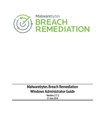
experiencing a deep-seated rotational failure that originated on the upslope side of both tracks andterminated near the bottom of the down slope.SITE LOCATION AND GEOLOGIC SETTINGThe regional geology underlying the site consists of the Kope Formation. The Kope Formation is awidespread geologic unit covering much of the greater Cincinnati area and extending into Kentucky. TheKope formation generally consists of interbedded limestone and shale bedrock layers. Most notable arethe shale layers within the Kope, as these layers weather to a highly plastic, moisture sensitive clay withlow strength properties, when exposed to air or water. In areas where Kope Shales outcrop, the naturalslopes tend to be relatively flat, typically around a 3H:1V or flatter. The Kope Shales are well-known byDOTs and Railroads in this region, as they are often the root cause of much landslide activity, making theGreater Cincinnati/Northern KY area one of the most landslide prone regions in the county. Landslides areoften related to wet weather as groundwater fluctuations tend to over-saturate soil overburden, causing itto become heavier, and at the same time weaken the underlying weathered shale creating potentialfailure/slide surfaces. Based on the borings performed, Wood confirmed that the site is underlain by a weakshale layer, part of the Kope Formation, and thereby the likely contributor to the slope failure.DESIGN & CONSTRUCTIONAt the start of the design, Wood worked closely with Fenton to determine steel piling sizes available toprovide a stabilization design that could be implemented promptly, without delays due to procurement.Ultimately the analysis showed that an anchored soldier pile wall, consisting of rock socketed HP14x89 at5-foot spacing with 88-kip capacity anchors drilled into bedrock would be required to satisfy and arrestglobal stability concerns. As the progression of the design overlapped with emergency responseconstruction, Wood also worked closely with Nicholson to field adjust anchor locations to avoid obstructionsduring drilling and still maintain the design intent.Figure 1. Typical cross section of progressive slope failure and design solution.
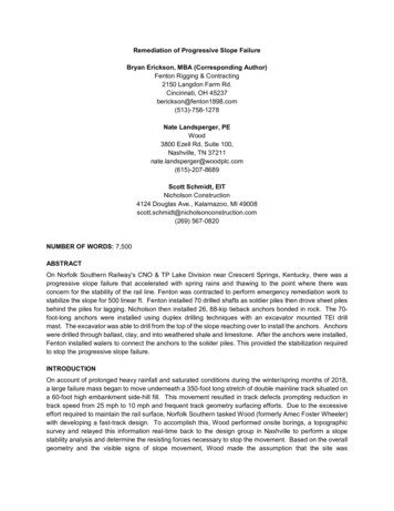
Soldier Pile InstallationDue to the narrow site and the difficult means to access it, the work had to progress in an essentially a startto finish relationship with very few over-lapping activities. It was determined that the installation of thesoldier piles would start on the far north end of the site – the point furthest away from the access road, andprogress to the south back towards the entrance of the site. As holes were drilled into rock, the drill rig wasbacked out past the access road to accommodate the installation of the HP14x89 soldier piles as well asthe required concrete. When piles were being set and concrete being cast, no other work could take place.Soldier pile installation began in late April of 2018 and lasted until mid-June of 2018. Equipment used forinstallation of the caissons and rock sockets was a Soilmec 219 drill rig with various casing sizes and bitsizes. Depth of soldier piles varied based on the location of which they were installed but generally, suitablebedrock was at its deepest point on the far north end of the site, progressing upward the further south thepiles were installed. Deepest pile installation was near 50 feet in depth from existing groundline and at itsmost shallow point depth was near 15 to 20 feet. As drilling began it was found that the sub surfaceconditions had very unstable fill and very caustic materials which meant that not only could a hole not beleft open for more than 24 hours, but also that drilling the next location in sequence from one that waspreviously drilled could cause cave-ins and other issues hindering production. After starting at pile location1 it was determined to progress with a staggered drilling sequence as opposed to a sequential install (1, 3,5, 2, 4, 6, 8, 10, 12, 7, 9, 11 as opposed to 1, 2, 3, 4, 5.).Figure 2. Installation of caissons and rock sockets to facilitate the installation of HP14x89 piling.Installation of HP14x89 piling followed closely behind the installation of the caissons and rocksockets to satisfy the project requirements of not leaving a hole open for more than 24 hours, but also to
prevent any further cave-ins. Due to the narrow site access, a 38-ton boom truck was utilized to assist ininstallation of the piling along with on-site excavators with vibratory hammer attachments. As soon as thepiling was installed, concrete was released to the project site. Prior to placing concrete, the piles wereadequately braced in both the X and Y axis’ and made sure they were plum and at the required 5’ intervalsto not conflict with sheet pile spacing for installation of the lagging.Figure 3. Installation of Soldier piles. Notice the gap between the first two piles showing the staggereddrilling sequence.Sheet Pile InstallationAs mentioned earlier, Wood worked closely with Fenton to determine which materials would be acceptablebased on availability of materials to expedite the project completion to avoid further slope failure. Since thesheet piling was determined not to be structural as it relates to preventing further slope movement, butmore so to simply hold back the backfill, a cold rolled section of sheet piling was deemed acceptable.Equipment utilized for installation of the SKZ-16 sheet piling was a CAT 320 track excavator with a Herculesmanufactured Sonic Side Grip SP60 Vibratory Hammer. Once soldier pile installation reached pile locationnumber 40, then it was determined that with the site limitations, sheet piling could be stocked on the northend of the site and could continue uninterrupted and not impeded with installation of the soldier piles. Depthof sheeting was only to be 10’ to simply hold back the fill. Sheeting was installed to top of concrete at each
of the soldier pile locations. Once all sheeting was installed the backfill progressed as needed to facilitatethe installation of the tiebacks at a later date.Figure 4. Installation of SKZ-16 sheet piling.
Figure 5. All sheeting installed and backfilled, ready for waler and tieback installation.Tieback InstallationTwenty-five 88-kip and two 100-kip tieback strand anchors were installed by Nicholson ranging in lengthfrom 70–94 ft. Duplex drilling was used which involved drilling into the slope at a 45 angle from horizontalthrough the sheet piles using a TEI drill mast mounted on an excavator with a down-the-hole hammer and5.5 in. outer diameter steel casing while flushing out the drill cuttings with compressed air. The 3-strandanchor tendons were then inserted into the drill hole and neat cement grout was pumped into the drill hole.The casing was then withdrawn while replacing the volume of each casing length with grout. This procedureallowed the drilling to be done from the top of the wall, while reaching over the sheet piles on the slopewhere machines could not traverse. This also allowed train traffic to continue unimpeded.Most anchors were drilled perpendicular to the wall, however, due to a culvert that crossed beneath thesite, 4 anchors had to be skewed 30 to the east so that they ran parallel with this culvert (Figure 5). Theculvert was then “bridged” over with a larger waler (Figure 6).
Figure 6. Plan view of both main lines and culvert traversing beneath the site. Tiebacks are shown asarrows.Figure 7. Drilling for tieback installation by Nicholson.
Figure 8. Larger waler can be seen in this photo “bridging” over the culvert traversing beneath the site aswell as the skewed anchors in the foreground.After drilling and grouting the anchors in place, wedge plates were welded to the front of each soldier pileand walers were then welded to the wedge plates for the anchor to bear on. A steel tube referred to as atrumpet was then inserted over the exposed anchor strands between the sheet piles and the waler andfilled with grout for corrosion protection of the tieback strands.Once all of the anchors were drilled and grouted and the grout reached a compressive strength of 4,000psi, each anchor was stressed with a calibrated hydraulic jack to 133% of the design load. After passingthis test, each anchor was locked off at the design load and capped for permanent corrosion protection.CONCLUSIONS & LESSONS LEARNEDSite access and the physical limitations of this project was everything. It played a major role in all decisionmaking. Had this site allowed for a wider access road and staging area then the work could have beencompleted in a much more expeditious manner. As a result, coordination between Norfolk Southern, Wood,Fenton, and Nicholson was key to ensure that work progressed in the most efficient way possible and didnot hinder one task from getting completed. As such, no one task took a priority over the others becauseeach work task was started and completed with very little lag or overlap from the next work task.One challenge that arose was that the bedrock surface sloped down unexpectedly such that the tiebackswere “chasing” the slope of this rock in order to bond in it. This meant that upon drilling the tieback holes,it was found that the strand lengths that were ordered for several of the tiebacks were too short (even after
having been ordered longer than required) to meet the designed bond length in rock. Therefore, longertieback strands had to be ordered. This is part of the risk of not having a complete picture of what is trulygoing on in the ground and another boring on the other side of the track to provide the rock surface slopein this direction would have possibly eliminated this 26,500 surprise.Due to the sense of urgency surrounding this project, the collaboration of the design teams with theinstallation teams was key to its success. Norfolk Southern and Wood worked closely with Fenton todetermine the best most available materials for installation and they followed progress very closely to makesure that if any changes were needed during installation that they were handled and delivered back to theinstall team with very little downtime. This helped to ensure that not only the desired result was achievedbut that all work was installed according to AREMA standards and specifications. Furthermore, NorfolkSouthern and Wood worked very closely with Nicholson to facilitate a very expeditious install of the tiebackanchors and as such difficult drilling conditions were encountered, the problems and fixes were remediedvery quickly because of the quasi design-build nature of this project. Collaboration between all partiesproved to be vital and a major key to the project's success.ACKNOWLEDGEMENTSThe authors would like to thankDavid Becker, PE – Norfolk SouthernWill Graham – Norfolk SouthernJeff Brewsaugh Sr. - Superior Steel Service of Cincinnati, OH (Handrail and Waler Materials)Alex Granger – Skyline Steel of Cincinnati, OH (H-Piling and Sheet Piling)LIST OF FIGURESFigure 1. Typical cross section of progressive slope failure and design solution. . 2Figure 2. Installation of caissons and rock sockets to facilitate the installation of HP14x89 piling. . 3Figure 3. Installation of Soldier piles. Notice the gap between the first two piles showing the staggereddrilling sequence. . 4Figure 4. Installation of SKZ-16 sheet piling. .
Equipment utilized for installation of the SKZ -16 sheet piling was a CAT 320 track excavator with a Hercules manufactured Sonic Side Grip SP60 Vibratory Hammer. Once soldier pile installation reached pile location number 40, then it was determined that with the site limitations, sheet piling could be stocked on the north