Transcription
Westinghouse Technology Systems ManualSection 7.4General Electric Turbine and Auxiliaries
TABLE OF CONTENTS7.4 GENERAL ELECTRIC TURBINE AND AUXILIARIES. 7.4-17.4.1 Introduction . 7.4-17.4.2 Main Turbine . 7.4-17.4.2.1 System Description . 7.4-17.4.2.2 Component Descriptions . 7.4-27.4.3 Gland Steam System . 7.4-47.4.3.1 System Description . 7.4-47.4.3.2 Component Descriptions . 7.4-57.4.3.3 System Operation . 7.4-67.4.4 Turbine Lubricating Oil System . 7.4-67.4.4.1 System Description . 7.4-67.4.4.2 Component Descriptions . 7.4-77.4.4.3 System Operation . 7.4-107.4.5 Moisture Separator Reheaters . 7.4-117.4.5.1 System Description . 7.4-117.4.5.2 Component Descriptions . 7.4-117.4.5.3 System Operation . 7.4-127.4.6 Summary. 7.4-13LIST OF FIGURES7.4-1 . Main Turbine Cross Section7.4-2 . Main Steam System - Low Pressure7.4-3 . Stop Valve7.4-4 . Control Valve7.4-5 . Combined Intermediate Valve7.4-6 . Gland Steam System7.4-7 . Turbine Glands7.4-8 . Turbine Lubricating Oil System7.4-9 . Moisture Separator Reheater (End View)USNRC HRTD7.4-iRev 0803
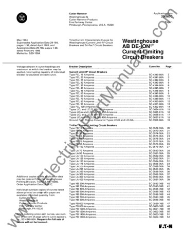
7.4 GENERAL ELECTRIC TURBINE AND AUXILIARIESLearning Objectives:1. State the purposes of the turbine and turbine auxiliaries.2. Identify the sources of heating steam to the moisture separator reheaters(MSRs).3. State the purposes of the following turbine valves:a. Stop valves,b. Control valves, andc. Combined intermediate valves.7.4.1 IntroductionThe purposes of the turbine and auxiliaries are as follows:1. To convert the thermal energy of the steam to mechanical energy to turn themain generator,2. To provide turbine shaft sealing,3. To provide turbine-generator lubricating oil, and4. To provide dry, superheated steam to the low pressure turbines to reducemoisture erosion and to increase plant efficiency.7.4.2 Main Turbine7.4.2.1System DescriptionThe main turbine consists of one high pressure turbine and three low pressureturbines coupled to a single shaft. The four turbines that comprise the main turbineare coupled to the generator and exciter; they serve as the prime mover for thesecomponents. A cross-section of the turbine is shown in Figure 7.4-1. Steam entersthe main turbine at the high pressure turbine through the turbine stop (throttle) andcontrol (governor) valves.The thermal energy of the steam is converted to mechanical energy in the highpressure turbine, and the steam is exhausted to the moisture separator reheaters.In each MSR the steam is dried, reheated, and superheated prior to its entry into thelow pressure turbines. The superheated steam is routed through the intermediatestop and intercept valves as it travels from the MSRs to the low pressure turbines.Energy conversion occurs again in the low pressure turbines as the steam expandsinto the vacuum of the main condenser.USNRC HRTD7.4-1Rev 0803
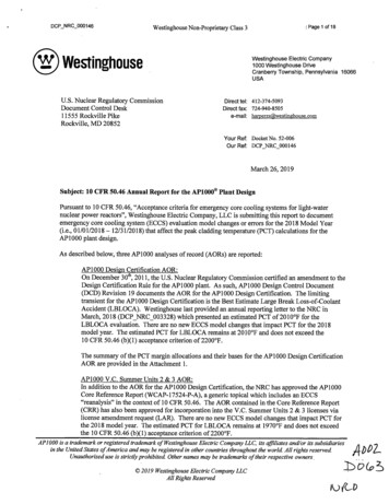
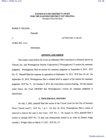
7.4.2.2Component DescriptionsHigh Pressure TurbineThe high pressure turbine is a double-flow turbine with six stages in each direction.The first three stages are rateau (impulse) stages, and the last three stages arereaction stages. Steam enters the four nozzle block segments at the center of thehigh pressure turbine and flows axially in both directions. About one fifth of thesteam entering the turbine at 100% power is extracted from the second and fourthstages for moisture removal, feedwater heating, and reheating of the high pressureturbine exhaust steam. Most of the steam supplied to the turbine does work in allsix stages and exhausts through six cold reheat (cross-around) lines to the twoMSRs, as shown in Figure 7.4-2.The turbine rotor assembly, which consists of the rotor and the turbine wheels (thewheels contain the rotating blades), is machined from a single casting. The rotatingblades (buckets) are secured to the wheels with dovetail joints. The turbine rotor issupported by two elliptical journal bearings, which carry the rotor’s weight and limitits radial motion.Stop ValvesThe four stop valves supply steam to the main turbine and close rapidly to isolatethe steam flow to the high pressure turbine when the turbine trips. The stop valvesare located just upstream of the control valves. The stop valve casings are weldedto the control valve casings, and all four casing units are welded together to form asingle assembly. The below-seat chambers of the stop valves are cross-connected,as are the steam headers upstream of the stop valves; this arrangement allows theopening of one stop valve to equalize the pressure across all four valve disks.The stop valves are identical 28-in., reverse-seating globe valves, with the exceptionthat the #2 stop valve contains an internal bypass valve (see Figure 7.4-3). Openingthe internal bypass valve accounts for a small amount of valve stem movement forthis valve. When opened, the bypass valve uncovers holes in the main valve disk,allowing steam to flow from the inlet to the outlet with the main disk seated.Opening the internal bypass valve in the #2 stop valve equalizes the pressureacross the stop valve main disks to allow valve opening (a stop valve’s hydraulicoperator cannot open the valve with a differential pressure of greater than 150 psiacross the main disk). The bypass valve is also used to provide warming steam forthe turbine steam chests and the high pressure turbine shell during turbine startups(see Chapter 11 .5).The #2 stop valve position is controlled by the electrohydraulic control (EHC)system. The other three stop valves are Aslaved@ to the #2 stop valve through a limitswitch associated with the #2 stop valve. (See Chapter 11.5 for details on stopvalve control.)USNRC HRTD7.4-2Rev 0803
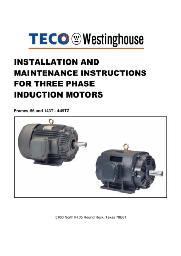
Control ValvesThe four control valves, located immediately downstream of the stop valves, arepositioned by the EHC system for the control of turbine speed and load (seeChapter 11.5). Rapid closure of the control valves when the turbine trips providesredundant isolation of the steam flow to the high pressure turbine. The controlvalves admit steam to the high pressure turbine via four internal nozzle blocksegments at the center of the turbine rotor.Each of the control valves is a 28-in., spherically seated globe valve (see Figure 7.44). Each valve contains a small internal pilot valve within the main valve disk.When a control valve is opened, the first portion of stem movement opens the pilotvalve, thereby reducing the differential pressure across the main valve disk andreducing the opening force required of the valve’s hydraulic operator. Further stemmovement causes the pilot valve to engage the main disk and open the valve.Low Pressure TurbinesEach of the three low pressure turbines is a double-flow, condensing turbine withseven reaction stages in each direction. The MSRs supply steam via the combinedintermediate valves to the center of each turbine; the steam then flows axially inboth directions. About one fourth of the steam entering each low pressure turbine at100% power is extracted from the seventh, eighth, tenth, and eleventh stages formoisture removal and feedwater heating (the low pressure turbine stages arenumbered 7 - 13). Most of the steam supplied to each turbine does work in allseven stages and exhausts to the main condenser.The rotor of each low pressure turbine is machined from a single forging. Theturbine wheels are manufactured separately and shrunk onto the rotor. The rotatingblades are attached to the wheels with dovetail joints. Due to the steam expansionthat occurs in the low pressure turbine, the blade height and stage diameterincrease with each succeeding stage. The last-stage blading of each low pressureturbine is 38 in. long. Each low pressure turbine is supported by two journalbearings.Combined Intermediate ValvesEach of the six combined intermediate valves consists of two valves in one body,the intercept valve and the intermediate stop valve. Refer to Figure 7.4-5. The twovalves share the same seating surface but are equipped with separate operators.The intercept valves and intermediate stop valves are completely open duringnormal operation. All 12 valves shut when the turbine trips to provide redundantisolation of the low pressure turbines from the reheat steam supply. The interceptvalves can also shut partially or completely to limit turbine overspeed following aload rejection. Intercept valves #1, #2, and #3 are controlled by the EHC system;intercept valves #4, #5, and #6 are slaved to the controlled intercept valves throughlimit switches associated with the controlled valves. The intermediate stop valvesare automatically opened when the master trip reset pushbutton is depressed. (SeeChapter11.5 for a discussion of valve operation.)USNRC HRTD7.4-3Rev 0803
Each intercept valve disk is hollow and cylindrically shaped to accommodate thedisk of its associated intermediate stop valve. This arrangement permits theintermediate stop valve to open or close with the intercept valve completely closed.Equalizing holes in the intercept valve disk minimize the differential pressure acrossthe disk and allow opening of the intercept valve even against maximum reheatsteam pressure. Each intermediate stop valve can be opened with a differentialpressure across the seat of no greater than 150 psi. The intermediate stop valvesare thus opened during the turbine startup sequence before all other turbine valvesare opened so that the differential pressure across the valve seats is minimized.7.4.3 Gland Steam System7.4.3.1System DescriptionDuring plant operation the entry of air into and the exit of steam from the mainturbine must be prevented at those points where the rotor penetrates the turbinecasings. These functions are accomplished through the labyrinth design of therotor/casing penetrations (glands) and through the operation of the gland steamsystem. The system is designed to handle the steam and air flows that would existwith twice the normal turbine penetration clearances.The gland steam system (Figure 7.4-6) supplies steam to the turbine glands of thehigh and low pressure turbines and of the main feed pump turbines. During startupand low-load operation, the sealing steam distribution header has two sources ofsteam supply: the startup boiler and the main steam system. A regulating valvecontrols the steam pressure supplied by either source. In the initial phases of astartup from cold shutdown conditions, gland steam is supplied from the startupboiler. Once the plant has been heated up and an adequate supply of main steamis available, gland steam is supplied from the main steam system. The sealingsteam distribution header also receives low pressure stem leakage from the highpressure turbine stop and control valves.At higher plant powers (greater than approximately 40%), the direction of steam flowin portions of the gland steam system changes. Steam from inside the highpressure turbine casing leaks past the inner turbine glands and into the sealingsteam distribution header. Similarly, steam leaks from the main feed pump turbineglands to the distribution header (although at a much smaller flow rate). The steamleakage from these sources supplies the sealing steam for the low pressure turbineglands at high powers. The unloading valves on the distribution header relieve anyexcess steam pressure during this mode of operation. (Note: The arrows in Figure7.4-6 indicate the two possible flow directions in certain portions of the system.)Steam leakage from the inner turbine packing and air leakage through the outerturbine packing (see Figure 7.4-7) is extracted from the turbine glands by the steampacking exhauster. The exhauster condenses the incoming steam and returns thecondensate to the main condenser via a drain tank. The exhauster blowermaintains a slight vacuum in the exhauster and discharges air and othernoncondensible gases to the turbine building roof.USNRC HRTD7.4-4Rev 0803
7.4.3.2Component DescriptionsGland Seal Regulating ValveThe gland seal regulating valve (CV-3588 in Figure 7.4-6) is a four-in., air-operatedgate valve. The valve’s position is controlled by a pressure controller, whichsupplies instrument air to the valve’s operator based on the pressure sensed in thesealing steam distribution header. The pressure controller maintains the glandsteam supply pressure between 2.5 and 4.5 psig. Control of the distribution headerpressure by the regulating valve is expected only with turbine loads less than 40%.If the regulating valve or its associated controller is inoperable, the operator canmaintain the gland steam supply pressure with the regulating valve bypass valve(MO-3586), which is controlled with a control room switch.Unloading ValvesThe two unloading valves are eight-in., direct-acting backpressure regulating valves.Pressure from the regulating valve controller’s sensing line acts against spring forcein each unloading valve’s operator. The unloading valves are set to crack open witha gland steam pressure of 3.5 psig and to open fully with a pressure of 5.5 psig. Atloads greater than 40%, the unloading valves are open to relieve excess steamleakage from the high pressure turbine glands to the main condenser. The normalsteam flow through the unloading valves at full power is 19,190 lbm/hr. If the valvesare inoperable, the operator can manually dump steam to the condenser with themanual unloading valve (MO-3603), which is controlled with a control room switch.Turbine GlandsThe turbine glands contain labyrinth packing, which provide effective seals for theshaft penetrations. Each labyrinth seal is made up of stationary, spring-backedpacking rings and machined grooves in the turbine rotor (see Figure 7.4-7). Thepacking rings hold stationary teeth arranged concentrically, with very small radialclearances between the teeth and the rotor. The narrow passages between thestationary packing and the rotor produce a cumulative pressure drop, whichpresents a large resistance to steam or air flow in the axial direction. This sealdesign minimizes but does not totally eliminate steam outleakage and air inleakage;the applied sealing steam completely seals the glands.As shown in Figure 7.4-7, the high pressure turbine is sealed at both ends with threesets of packing. At low loads, sealing steam from the gland steam distributionheader pressurizes the annulus formed by the inner and middle sets of packing toprevent air inleakage into the turbine. Sealing steam which leaks past the middleset of packing, and air which leaks past the outer set, enter the annulus maintainedat a vacuum by the steam packing exhauster. At higher loads, the higher stagepressures inside the high pressure turbine casing prevent air inleakage. Instead,steam leaks past the inner set of packing and flows in the reverse direction to thegland steam distribution header to serve as the sealing steam supply for the lowpressure turbines. Again, any leakage of steam and/or air past the middle and outersets of packing is extracted by the steam packing exhauster.USNRC HRTD7.4-5Rev 0803
Sealing of the low pressure turbines, which exhaust to a vacuum, is alwaysaccomplished in the manner described for the high pressure turbine at low loads.Steam Packing ExhausterThe steam packing exhauster maintains a vacuum in the outer annuli of the turbineglands to prevent the escape of steam from the turbines into the turbine building.The exhauster is a shell-and-tube heat exchanger cooled by the turbine buildingcooling water system. The condensed steam is drained from the exhauster to themain condenser via a loop seal and drain tank. The drain tank level is maintainedby a level control valve in the drain line to the condenser. The slight vacuum in theexhauster shell is maintained by the exhauster blower.7.4.3.3System OperationDuring a plant startup, the gland steam system is placed in service before theturbine startup sequence is initiated. The initial source of steam to the gland steamsystem is the startup boiler. As the startup progresses and sufficient main steambecomes available, the gland steam supply source is transferred to the main steamsystem. During normal operation, the gland steam system distribution headerpressure is automatically maintained by the gland seal regulating valve and theunloading valves. Sealing steam to the turbine glands is maintained during ashutdown until the condenser vacuum is broken. This practice prevents an inrush ofcold air into the turbine casings, which could result in a bowed rotor. Operation ofthe gland steam system is not required during a shutdown after the condenservacuum has been broken.7.4.47.4.4.1Turbine Lubricating Oil SystemSystem DescriptionThe turbine lubricating oil system, illustrated in Figure 7.4-8, supports turbinegenerator operation by supplying lubricating oil to the eight turbine journal bearings,the thrust bearing, the two generator bearings, the two exciter bearings, and theturning gear. Under normal operating conditions, the main shaft oil pump, driven bythe turbine shaft, supplies oil to the turbine and generator bearings. The suctionhead for the main shaft oil pump is provided by the lubricating oil booster pump,which takes suction on the lubricating oil reservoir. In addition to supplying thebearing supply header, the main shaft oil pump also supplies oil to the hydraulicturbine which drives the lubricating oil booster pump. Return oil from the bearingsgravity drains into the lubricating oil reservoir.The turbine lubricating oil system includes additional pumps for supplying lubricatingoil when the turbine is not in service: the motor suction pump, the turning gear oilpump, and the emergency bearing oil pump. The lubricating oil system alsoincludes bearing lift oil pumps, which supply high pressure oil to turbine andgenerator bearings in support of turning gear operation. Detailed descriptions of thecomponents mentioned here are provided in the following section.USNRC HRTD7.4-6Rev 0803
The system is designed for fire safety. Any pressurized oil supply line which passesnear a hot steam line or potentially hot turbine component is enclosed within an oildrain line or guard pipe. The drain and guard pipes drain to the lubricating oilreservoir, ensuring that there is no loss of oil in the event of a supply line rupture.7.4.4.2Component DescriptionsMain Shaft Oil PumpThe main shaft oil pump maintains the normal bearing oil pressure under normaloperating conditions. The pump is a single-stage centrifugal pump driven by theturbine shaft through a step-up gear assembly and is located in the front standard.The pump suction is supplied with oil at 15 - 20 psig from the electrically drivenmotor suction pump during startups and from the lubricating oil booster pump duringnormal operation. The main shaft oil pump develops a discharge pressure sufficientfor turbine operation at turbine speeds greater than 1350 rpm. With the turbine atrated speed, the main shaft oil pump discharges oil at a pressure of 235 psig to thebooster pump turbine and bearing supply header.Motor Suction PumpThe motor suction pump supplies oil to the suction of the main shaft oil pump whenthe turbine speed is less than 1800 rpm. The pump is a single-stage centrifugalpump driven by a 60-hp ac motor. The pump is located inside the lubricating oilreservoir, and the motor is mounted atop the reservoir. The pump is startedmanually with a control room switch during turbine startups. With the turbine atrated speed, the pump is idle, and its control switch is in the automatic position. Themotor suction pump starts automatically when the lubricating oil booster pumpdischarge pressure falls below 10 psig.Lubricating Oil Booster PumpThe lubricating oil booster pump supplies the suction head required by the mainshaft oil pump during normal operation. The pump is a single-stage centrifugalpump driven by the discharge of the main shaft oil pump via a hydraulic turbine.The lubricating oil pump is located inside the lubricating oil reservoir. Under normaloperating conditions, it supplies a suction pressure of 15 - 20 psig to the main shaftoil pump. The booster pump turbine exhaust oil is supplied to the bearing supplyheader, where it joins the flow supplied directly by the main shaft oil pump.Turning Gear Oil PumpBecause the main shaft oil pump cannot provide adequate bearing lubrication withturbine speeds less than 1350 rpm, the turning gear oil pump is provided as thepumping source of lubricating oil during turbine startups and shutdowns. The pumpis a single-stage centrifugal pump driven by a 50-hp ac motor. The pump is locatedinside the lubricating oil reservoir, and the motor is mounted atop the reservoir. Thepump is operated manually during startups and shutdowns. With the turbine atrated speed, the pump is idle, and its control switch is in the automatic position. Theturning gear oil pump starts automatically when either the bearing supply headerUSNRC HRTD7.4-7Rev 0803
pressure falls below 15 psig or the main shaft oil pump discharge pressure fallsbelow 190 psig.Emergency Bearing Oil PumpThe emergency bearing oil pump supplies lubricating oil to the turbine and generatorbearings for the safe shutdown of the turbine-generator when ac power is notavailable. The pump is a single-stage centrifugal pump driven by a 30-hp dc motor.The pump is located inside the lubricating oil reservoir, and the motor is mountedatop the reservoir. Under normal operating conditions, the pump is idle, and itscontrol switch is in the automatic position. The emergency bearing oil pump startsautomatically whenever the turning gear oil pump discharge pressure is less than 10psig coincident with a main shaft oil pump discharge pressure of less than 180 psig.Baffler ValvesTwo flow regulating valves, called baffler valves, in the lubricating oil systemcorrectly apportion the main shaft oil pump discharge to the lubricating oil boosterpump turbine and the bearing supply header. The valves are manually adjusted sothat the bearing supply header pressure is maintained at 25 psig and that thedischarge pressure of the lubricating oil booster pump is maintained between 15and 20 psig.Lubricating Oil CoolersBefore it is supplied to the turbine bearings, the lubricating oil is cooled in one of thetwo lubricating oil coolers. As each is a 100% capacity cooler, only one is in serviceat a time. The in-service cooler is determined by the position of the transfer valve.Cooling water from the turbine building cooling water system flows through thetubes, and lubricating oil flows through the shell of the in-service cooler. A flowcontrol valve regulates the cooling water flow to maintain a lubricating oil reservoirtemperature of l20 F.Lubricating Oil ReservoirThe lubricating oil reservoir stores the return oil from the lubricating oil system andprovides the necessary suction head for each system pump located inside thereservoir. Oil gravity drains from the turbine and generator bearings and enters thereservoir through two wire screens arranged in series. The reservoir’s total capacityis 10,000 gal; the normally maintained oil volume is 7450 gal. The additionalcapacity accommodates the volume of oil which returns from the system pipingwhen the lubricating oil system is shut down. The reservoir level instrumentationsupplies high and low level alarms, with setpoints of " four in. from the normal level(five ft), and a high-high level alarm, with a setpoint of four in. below the top of thereservoir. The high-high level alarm warns of a potential overflow.Vapor ExtractorAir and other vapors are constantly removed from the lubricating oil reservoir by thevapor extractor. The extractor is a centrifugal blower driven by a 7.5-hp motor. TheUSNRC HRTD7.4-8Rev 0803
extractor takes suction on the reservoir and discharges through a mist eliminator tothe turbine building roof. Because the vapor extractor maintains a slight vacuum inthe reservoir, it also ventilates the lubricating oil drain lines from the turbine andgenerator bearings. Effective ventilation of the system enhances the removal ofsome of the contaminating influences that might affect the service life of thelubricating oil.Bearing Lift Oil PumpsThe lubricating oil supply lines to bearings #3 through #10 (eight journal bearingswhich support the three low pressure turbines and the generator) differ from theother oil supply lines in that they are provided with bearing lift oil pumps. Operationof the bearing lift oil pumps reduces the torque on the turning gear motor andreduces the turning gear teeth stresses. The lift oil pumps serve these purposes bysupplying high pressure oil to the lower halves of the bearings (the underside of theturbine shaft); the oil actually lifts the turbine shaft. In each bearing supplied by a liftoil pump, the high pressure oil passes through the lower half of the bearing into arecessed pocket. The pocket is located in the babbitt surface of the bearing. Whensufficient pressure is built up in all of the bearings, the shaft will lift approximatelytwo to five mils.Each of the eight bearing lift oil pumps is a positive displacement pump driven by afive-hp ac motor. Each of the pumps supplies a single bearing. Upon initial starting,each pump generates a discharge pressure of 3000 - 3500 psig. As the shaft lifts,the pressure drops to about 900 psig. Each pump has a filter in its suction line forthe removal of foreign material and a relief valve in its discharge line foroverpressure protection. Pump running indication is provided for each pump by apressure switch in its discharge line.The bearing lift oil pumps can be started manually with control room switches orautomatically through the operation of the low speed switch when the turbine speeddecreases to 1.5 rpm (indicating that turning gear operation is required; refer to theturning gear description in the following paragraphs). The lift oil pumps aremanually started when the turbine speed decreases to 900 rpm following a turbinetrip. A starting permissive for each pump is supplied by a pressure switch whichsenses the pressure in the pump’s suction line; a pump start is permitted whensuction pressure is greater than six psig. Similarly, a running pump will trip if itssuction pressure falls below one psig.Turning GearThe function of the turning gear is to prevent turbine shaft distortion when it is beingheated or cooled. Damage to the turbine because of rubbing between the movingand stationary components is therefore prevented. The turning gear slowly rotatesthe shaft when the turbine is shutdown and is being heated or cooled. The slowrotation ensures an even circumferential temperature distribution around the rotor.The turning gear is a motor-driven pinion that meshes with a bull gear located on theturbine shaft between bearings #8 and #9 (i.e., between the last low pressureUSNRC HRTD7.4-9Rev 0803
turbine and the generator). The pinion is driven at 900 rpm by a 60-hp, single-speedmotor. The pinion drives the bull gear (and thus the turbine shaft) at 1.5 rpm.The turning gear can be manually engaged by turning a wrench on the projection ofthe shaft engaging mechanism or by depressing a pushbutton at the local turninggear control panel. The pushbutton energizes a solenoid-operated valve whichapplies instrument air pressure to the turning gear engaging mechanism. The airpressure acts on a piston which, through mechanical linkage, forces the pinion tomesh with the bull gear. The solenoid-operated valve is also energized (and theturning gear engagement sequence is initiated) when the turning gear isautomatically engaged by the low speed switch, which actuates when the turbinespeed drops to 1.5 rpm. Automatic engagement of the turning gear or manualengagement with the local pushbutton is permitted when the turning gear motor isrunning.The turning gear motor is started manually with a local control switch orautomatically by the low speed switch described above. With an automatic start ofthe turning gear, there is a time delay between motor starting and gear engagementto ensure that the turning gear motor starts unloaded. Three permissives must besatisfied to start the turning gear motor either ma
100% power is extracted from the seventh, eighth, tenth, and eleventh stages for moisture removal and feedwater heating (the low pressure turbine stages are numbered 7 - 13). Most of the steam supplied to each turbine does work in all seven stages and exhausts to the main condenser.