Transcription
FUNDAMENTALS OFLIGHT MICROSCOPYAND ELECTRONICIMAGING
FUNDAMENTALS OFLIGHT MICROSCOPYAND ELECTRONICIMAGINGDouglas B. MurphyA JOHN WILEY & SONS, INC., PUBLICATION
The cover image is an optical path in the Zeiss Axiophot upright microscope. For details, see the legend to therelated Color Plate 1-2. (Courtesy Carl Zeiss, Inc.)Frontispiece. Diatom exhibition mount, bright-field and dark-field microscopy. (This striking exhibition slidefor the light microscope was prepared by Klaus Kemp, Somerset, England.)This book is printed on acid-free paper.Copyright 2001 by Wiley-Liss, Inc. All rights reserved.Published simultaneously in Canada.While the authors, editor, and publisher believe that drug selection and dosage and the specification and usageof equipment and devices, as set forth in this book, are in accord with current recommendations and practiceat the time of publication, they accept no legal responsibility for any errors or omissions, and make no warranty, express or implied, with respect to material contained herein. In view of ongoing research, equipmentmodifications, changes in governmental regulations and the constant flow of information relating to drug therapy, drug reactions, and the use of equipment and devices, the reader is urged to review and evaluate the information provided in the package insert or instructions for each drug, piece of equipment, or device for, amongother things, any changes in the instructions or indication of dosage or usage and for added warnings and precautions.No part of this publication may be reproduced, stored in a retrieval system or transmitted in any form or byany means, electronic, mechanical, photocopying, recording, scanning or otherwise, except as permittedunder Sections 107 or 108 of the 1976 United States Copyright Act, without either the prior written permission of the Publisher, or authorization through payment of the appropriate per-copy fee to the Copyright Clearance Center, 222 Rosewood Drive, Danvers, MA 01923, (978) 750-8400, fax (978) 750-4744. Requests to thePublisher for permission should be addressed to the Permissions Department, John Wiley & Sons, Inc., 605Third Avenue, New York, NY 10158-0012, (212) 850-6011, fax (212) 850-6008, E-Mail: PERMREQ @WILEY.COM.For ordering and customer service call 1-800-CALL-WILEY.Library of Congress Cataloging-in-Publication Data:Murphy, Douglas B.Fundamentals of light microscopy and electronic imaging / Douglas B. Murphy.p. cm.Includes bibliographical references (p. 357).ISBN 0-471-25391-X1. Microscopy. I. Title.QH211.M87 2001502 .8 2—dc21Printed in the United States of America.10 9 8 7 6 5 4 3 2 12001024021
CONTENTSPrefacexi1. FUNDAMENTALS OF LIGHT MICROSCOPY1Overview1Optical Components of the Light Microscope1Note: Inverted Microscope Designs3Aperture and Image Planes in a Focused, Adjusted Microscope4Note: Using an Eyepiece Telescope to View the Objective Back ApertureKoehler Illumination6Adjusting the Microscope for Koehler Illumination7Note: Summary of Steps for Koehler Illumination7Note: Focusing Oil Immersion Objectives11Precautions for Handling Optical Equipment11Exercise: Calibration of Magnification122. LIGHT AND COLOR15Overview15Light as a Probe of Matter15Light as Particles and Waves18The Quality of Light20Properties of Light Perceived by the Eye21Physical Basis for Visual Perception and ColorPositive and Negative Colors 24Exercise: Complementary Colors26223. ILLUMINATORS, FILTERS, AND ISOLATIONOF SPECIFIC WAVELENGTHSOverview29Illuminators and Their Spectra52929v
viCONTENTSDemonstration: Spectra of Common Light Sources33Illuminator Alignment and Bulb Replacement34Demonstration: Aligning a 100 W Mercury Arc Lamp in an Epi-illuminator 35“First On—Last Off ”: Essential Rule for Arc Lamp Power Supplies36Filters for Adjusting the Intensity and Wavelength of Illumination37Effects of Light on Living Cells414. LENSES AND GEOMETRICAL OPTICSOverview43Image Formation by a Simple Lens43Note: Real and Virtual Images45Rules of Ray Tracing for a Simple Lens46Object-Image Math46The Principal Aberrations of Lenses50Designs and Specifications of Objective Lenses53Condensers56Oculars56Microscope Slides and Coverslips57The Care and Cleaning of Optics58Exercise: Constructing and Testing an Optical Bench Microscope5. DIFFRACTION AND INTERFERENCEIN IMAGE FORMATION435961Overview61Defining Diffraction and Interference61The Diffraction Image of a Point Source of Light64Demonstration: Viewing the Airy Disk with a Pinhole Aperture66Constancy of Optical Path Length Between the Object and the Image68Effect of Aperture Angle on Diffraction Spot Size69Diffraction by a Grating and Calculation of Its Line Spacing, d71Demonstration: The Diffraction Grating75Abbe’s Theory for Image Formation in the Microscope77Diffraction Pattern Formation in the Back Aperture of the Objective Lens 80Demonstration: Observing the Diffraction Image in the Back FocalPlane of a Lens81Preservation of coherence: An Essential Requirement for Image Formation 82Exercise: Diffraction by Microscope Specimens846. DIFFRACTION AND SPATIAL RESOLUTIONOverview85Numerical Aperture85Spatial Resolution87Depth of Field and Depth of Focus90Optimizing the Microscope Image: A Compromise Between SpatialResolution and Contrast91Exercise: Resolution of Striae in Diatoms9385
CONTENTS7. PHASE CONTRAST MICROSCOPYAND DARK-FIELD MICROSCOPY97Overview97Phase Contrast Microscopy97The Behavior of Waves from Phase Objects in Bright-Field Microscopy 99The Role of Differences in Optical Path Lengths103The Optical Design of the Phase Contrast Microscope103Alignment 106Interpretating the Phase Contrast Image106Exercise: Determination of the Intracellular Concentration of Hemoglobin inErythrocytes by Phase Immersion Refractometry110Dark-Field Microscopy112Theory and Optics112Image Interpretation115Exercise: Dark-Field Microscopy1168. PROPERTIES OF POLARIZED LIGHT117Overview117The Generation of Polarized Light117Demonstration: Producing Polarized Light with a Polaroid Filter119Polarization by Reflection and Scattering121Vectorial Analysis of Polarized Light Using a Dichroic Filter121Double Refraction in Crystals124Demonstration: Double Refraction by a Calcite Crystal126Kinds of Birefringence127Propagation of O and E Wavefronts in a Birefringent Crystal128Birefringence in Biological Specimens130Generation of Elliptically Polarized Light by Birefringent Specimens1319. POLARIZATION MICROSCOPY135Overview135Optics of the Polarizing Microscope136Adjusting the Polarizing Microscope138Appearance of Birefingent Objects in Polarized Light139Principles of Action of Retardation Platesand Three Popular Compensators139Demonstration: Making a Plate from a Piece of Cellophane143Exercise: Determination of Molecular Organization in Biological StructuresUsing a Full Wave Plate Compensator14810. DIFFERENTIAL INTERFERENCE CONTRAST (DIC)MICROSCOPY AND MODULATION CONTRASTMICROSCOPYOverview153The DIC Optical System153DIC Equipment and Optics155The DIC Prism157Demonstration: The Action of a Wollaston Prism in Polarized Light153158vii
viiiCONTENTSFormation of the DIC Image159Interference Between O and E Wavefrontsand the Application of Bias Retardation160Alignment of DIC Components161Image Interpretation166The Use of Compensators in DIC Microscopy167Comparison of DIC and Phase Contrast Optics168Modulation Contrast Microscopy168Contrast Methods Using Oblique Illumination169Alignment of the Modulation Contrast Microscope172Exercise: DIC Microscopy17311. FLUORESCENCE MICROSCOPY177Overview177Applications of Fluorescence Microscopy178Physical Basis of Fluorescence179Properties of Fluorescent Dyes182Demonstration: Fluorescence of Chlorophyll and Fluorescein183Autofluorescence of Endogenous Molecules185Demonstration: Fluorescence of Biological MaterialsUnder Ultraviolet Light189Arrangement of Filters and the Epi-illuminatorin the Fluorescence Microscope189Objective Lenses and Spatial Resolution in Fluorescence Microscopy194Causes of High-Fluorescence Background196The Problem of Bleed-Through with Multiply Stained Specimens197Examining Fluorescent Molecules in Living Cells198Exercise: Fluorescence Microscopy of Living Tissue Culture Cells19912. CONFOCAL LASER SCANNING MICROSCOPY205Overview205The Optical Principle of Confocal Imaging208Demonstration: Isolation of Focal Plane Signalswith a Confocal Pinhole211Advantages of CLSM Over Wide-Field Fluorescence Systems213Criteria Defining Image Quality and the Performanceof an Electronic Imaging System215Electronic Adjustments and Considerationsfor Confocal Fluorescence Imaging217Photobleaching223General Procedure for Acquiring a Confocal Image224Two-Photon and Multi-Photon Laser Scanning Microscopy226Confocal Imaging with a Spinning Nipkow Disk229Exercise: Effect of Confocal Variables on Image Quality23013. VIDEO MICROSCOPYOverview233Applications and Specimens Suitable for Video233233
CONTENTSConfiguration of a Video Camera System234Types of Video Cameras236Electronic Camera Controls238Demonstration: Procedure for Adjusting the Light Intensityof the Video Camera and TV Monitor241Video Enhancement of Image Contrast242Criteria Used to Define Video Imaging Performance245Aliasing249Digital Image Processors249Image Intensifiers250VCRs 251Systems Analysis of a Video Imaging System252Daisy Chaining a Number of Signal-Handling Devices254Exercise: Contrast Adjustment and Time-Lapse Recordingwith a Video Camera25514. DIGITAL CCD MICROSCOPY259Overview259The Charge-Coupled Device (CCD Imager)260CCD Architectures267Note: Interline CCDs for Biomedical Imaging268Analogue and Digital CCD Cameras269Camera Acquisition Parameters Affecting CCD Readoutand Image Quality 269Imaging Performance of a CCD Detector271Benefits of Digital CCD Cameras276Requirements and Demands of Digital CCD Imaging276Color Cameras277Points to Consider When Choosing a Camera278Exercise: Evaluating the Performance of a CCD Camera27915. DIGITAL IMAGE PROCESSINGOverview283Preliminaries: Image Display and Data Types284Histogram Adjustment285Adjusting Gamma ( ) to Create Exponential LUTs287Flat-Field Correction289Image Processing with Filters292Signal-to-Noise Ratio299Exercise: Flat-Field Correction and Determination of S/N Ratio28330516. IMAGE PROCESSING FOR SCIENTIFICPUBLICATIONOverview307Image Processing: One Variable Out of Many Affecting the Appearanceof the Microscope Image307The Need for Image Processing309307ix
xCONTENTSVarying Processing Standards309Record Keeping During Image Acquisition and Processing310Note: Guidelines for Image Acquisition and Processing310Use of Color in Prints and Image Displays312Colocalization of Two Signals Using Pseudocolor313A Checklist for Evaluating Image Quality315Appendix I317Appendix II321Appendix III329Glossary331References 357Index 361
PREFACEThroughout the writing of this book my goal has been how to teach the beginner how touse microscopes. In thinking about a cover, my initial plan was to suggest a silhouetteof a microscope under the title “Practical Light Microscopy.” However, the needs of thescientific community for a more comprehensive reference and the furious pace of electronic imaging technologies demanded something more. Practitioners of microscopyhave long required an instructional text to help align and use a microscope—one thatalso reviews basic principles of the different optical modes and gives instructions onhow to match filters and fluorescent dyes, choose a camera, and acquire and print amicroscope image. Advances in science and technology have also profoundly changedthe face of light microscopy over the past ten years. Instead of microscope and film camera, the light microscope is now commonly integrated with a CCD camera, computer,software, and printer into electronic imaging systems. Therefore, to use a modernresearch microscope, it is clear that research scientists need to know not only how toalign the microscope optics, but also how to acquire electronic images and performimage processing. Thus, the focus of the book is on the integrated microscope system,with foundations in optical theory but extensions into electronic imaging. Accordingly,the cover shows the conjugate field and aperture planes of the light microscope underthe title “Fundamentals of Light Microscopy and Electronic Imaging.”The book covers three areas: optical principles involved in diffraction and imageformation in the light microscope; the basic modes of light microscopy; and the components of modern electronic imaging systems and the basic image-processing operationsthat are required to prepare an image. Each chapter is introduced with theory regardingthe topic at hand, followed by descriptions of instrument alignment and image interpretation. As a cell biologist and practitioner of microscopy rather than a physicist or developer of new microscope equipment and methods, the reader will notice that I havefocused on how to align and operate microscopes and cameras and have given somewhatabbreviated treatment to the physical theory and principles involved. Nevertheless, thetheory is complete enough in its essentials that I hope even experienced microscopistswill benefit from many of the descriptions. With the beginner microscopist in mind,each chapter includes practical demonstrations and exercises. The content, though notdifficult, is inherently intricate by nature, so the demonstrations are valuable aids inabsorbing essential optical principles. They also allow time to pause and reflect on thexi
xiiPREFACEeconomy and esthetic beauty of optical laws and principles. If carried out, the demonstrations and exercises also offer opportunities to become acquainted with new biological specimens that the reader may not have confronted or seen before by a new mode oflight microscopy. Lists of materials, procedures for specimen preparation, and answersto questions in the problem sets are given in an Appendix. A basic glossary has also beenincluded to aid readers not already familiar with complex terminology. Finally, becausethe text contains several detailed descriptions of theory and equipment that could beconsidered ancillary, an effort has been made to subordinate these sections so as to notobscure the major message.Special thanks are due to many individuals who made this work possible. ForemostI thank profoundly my wife, Christine Murphy, who encouraged me in this work anddevoted much time to reading the text and providing much assistance in organizing content, selecting figures, and editing text. I also thank the many students who have takenmy microscope courses over the years, who inspired me to write the book and gave valuable advice. In particular, I would like to thank Darren Gray of the Biomedical Engineering Department at Johns Hopkins, who worked with me through every phrase andequation to get the facts straight and to clarify the order of presentation. I would also liketo thank and acknowledge the help of many colleagues who provided helpful criticismsand corrections to drafts of the text, including Drs. Bill Earnshaw (University of Edinburgh), Gordon Ellis (University of Pennsylvania), Joe Gall (Carnegie Institution,Department of Embryology), Shinya Inoué (Marine Biological Laboratory), ErnstKeller (Carl Zeiss, Inc.), John Russ (North Carolina State University), Kip Sluder (University of Massachusetts Medical School), and Ken Spring (National Institutes ofHealth). Finally, I wish to thank many friends and colleagues who provided facts,advice, and much encouragement, including Ken Anderson, Richard Baucom, AndrewBeauto, Marc Benvenuto, Mike Delannoy, Fernando Delaville, Mark Drew, DavidElliott, Vickie Frohlich, Juan Garcia, John Heuser, Jan Hinsch, Becky Hohman, ScotKuo, Tom Lynch, Steven Mattessich, Al McGrath, Michael Mort, Mike Newberry,Mickey Nymick, Chris Palmer, Larry Philips, Clark Riley, Ted Salmon, Dale Schumaker, and Michael Stanley.I also give special acknowledgment and thanks to Carl Zeiss, Leica MicrosystemsNikon Corporation, and Olympus America for providing the color plates that accompany the book.Finally, I thank Luna Han and her assistants at John Wiley & Sons for their greatpatience in receiving the manuscript and managing the production of the book.Douglas B. MurphyBaltimore, Maryland
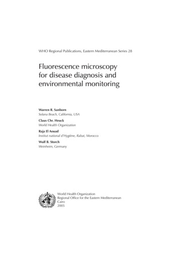
Color PlatesColor Plate 4-1. Optical path in the Olympus BX60 upright microscope. The microscope is fitted with a transilluminator (bottom) and epi-illuminator (top) and has infinity-corrected optics.Lenses, filters, and prisms are light blue. Light passing through the objective lens emerges andpropagates as a parallel beam of infinite focus, which is collected by an internal tube lens (Telanlens) as an aberration-free image in the real intermediate image plane. The Telan lens is locatedwhere the black trinocular headpiece joins the white microscope body. The infinity space betweenobjective and Telan lens allows insertion of multiple optical devices (fluorescence filter sets,waveplate retarders, DIC prisms, analyzer, and others) without altering the magnification of theimage. This color plate was provided by Olympus America, Inc.
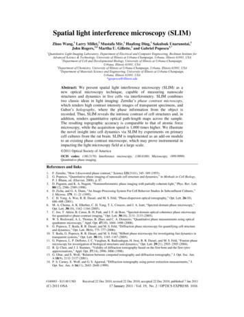
Color PlatesTVColor Plate 4-2. Optical path in the Zeiss Axiovert-135 inverted microscope. The microscope is fitted with a transilluminator (top) and epi-illuminator (bottom) and uses infinity-corrected optics. This plate shows the locations,marked by pairs of arrows, of multiple field planes (full beam diameter, bright yellow) and aperture planes (fullbeam diameter, dull gold.) Lens, mirror, and prism locations are shown in light blue. In this design, the stage isfixed to the microscope body and the specimen focus dial raises and lowers the objective lens. The black squareoutline at the site of intersection of the epi-illuminator beam with the microscope axis marks the position wherefilter sets are inserted for fluorescence microscopy. The identifications of conjugate sets of focal planes aredescribed in Chapter 1. This color plate was provided by Carl Zeiss, Inc.
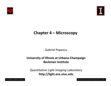
Color PlatesThickness 0.03418000.036Birefringence ( n)Relative phase retardation 00.0900.1000.1500.2000.300Birefringence ( n)Color Plate 9-1. Michel Lèvy chart showing four orders of the interference color spectrum.Removal of the wavelengths shown on the left edge of the chart through destructive interference yields the indicated interference colors. The chart is used to determine the phase difference between O and E rays for birefringent specimens examined in a polarizing microscopeequipped with a 1-plate compensator. The procedure for adjusting the compensator withwhite light illumination is described in Chapter 9. The Michel Lèvy chart also indicates therefractive index or thickness of a birefringent specimen if one of the two parameters is independently known. In geology, the chart is used to determine the identity, refractive index, orsection thickness of birefringent crystals (indicated by the diagonal lines on the chart). Colorplate courtesy Leica Microsystems Wetzlar GmbH.
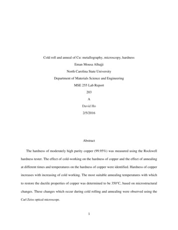
Color PlatesColor Plate 11-1. Transmission curves of common fluorescence filter sets. TOP: Filter sets for excitation at UV, violet,blue violet, blue, and green excitation wavelengths are shown.Each set shows the transmission profiles of an excitation bandpass filter (left), a dichroic mirror (labeled DM) and an emissionfilter (right). BOTTOM: Absorption and emission spectra ofsome common fluorochromes; the wavelengths correspondingto spectral maxima are indicated. In selecting a filter set toexcite fluorescence of a given dye, the excitation bandpass filtermust cover the excitation peak of the dye. Likewise, dichroicmirror and emission filter profiles must cover the principal emission peak of the dye. Thus, filter blocks B-2E and B-3A are suitable for examining FITC fluorescence, and block G-2A is suitable for examining the fluorescence of Rhodamine B200 andTRITC. This color plate was provided by The NikonCorporation, Inc.
CHAPTER1FUNDAMENTALSOF LIGHT MICROSCOPYOVERVIEWIn this chapter we examine the optical design of the light microscope and review procedures for adjusting the microscope and its illumination to obtain the best optical performance. The light microscope contains two distinct sets of interlaced focalplanes—eight planes in all—between the illuminator and the eye. All of these planesplay an important role in image formation. As we will see, some planes are not fixed, butvary in their location depending on the focus position of the objective and condenserlenses. Therefore, an important first step is to adjust the microscope and its illuminatorfor Koehler illumination, a method introduced by August Koehler in 1893 that givesbright, uniform illumination of the specimen and simultaneously positions the sets ofimage and diffraction planes at their proper locations. We will refer to these locationsfrequently throughout the book. Indeed, microscope manufacturers build microscopesso that filters, prisms, and diaphragms are located at precise physical locations in themicroscope body, assuming that certain focal planes will be precisely located after theuser has adjusted the microscope for Koehler illumination. Finally, we will practiceadjusting the microscope for examining a stained histological specimen, review the procedure for determining magnification, and measure the diameters of cells and nuclei ina tissue sample.OPTICAL COMPONENTS OF THE LIGHT MICROSCOPEA compound light microscope is an optical instrument that uses visible light to producea magnified image of an object (or specimen) that is projected onto the retina of the eyeor onto an imaging device. The word compound refers to the fact that two lenses, theobjective lens and the eyepiece (or ocular), work together to produce the final magnification M of the image such thatMfinal Mobj Moc.1
2FUNDAMENTALS OF LIGHT MICROSCOPYTwo microscope components are of critical importance in forming the image: (1) theobjective lens, which collects light diffracted by the specimen and forms a magnifiedreal image at the real intermediate image plane near the eyepieces or oculars, and (2) thecondenser lens, which focuses light from the illuminator onto a small area of the specimen. (We define real vs. virtual images and examine the geometrical optics of lensesand magnification in Chapter 4; a real image can be viewed on a screen or exposed on asheet of film, whereas a virtual image cannot.) The arrangement of these and other components is shown in Figure 1-1. Both the objective and condenser contain multiple lenselements that perform close to their theoretical limits and are therefore expensive. Asthese optics are handled frequently, they require careful attention. Other componentsless critical to image formation are no less deserving of care, including the tube and eyepieces, the lamp collector and lamp socket and its cord, filters, polarizers, retarders, andthe microscope stage and stand with coarse and fine focus dials.At this point take time to examine Figure 1-2, which shows how an image becomesmagnified and is perceived by the eye. The figure also points out the locations of important focal planes in relation to the objective lens, the ocular, and the eye. The specimenon the microscope stage is examined by the objective lens, which produces a magnifiedreal image of the object in the image plane of the ocular. When looking in the microscope, the ocular acting together with the eye’s cornea and lens projects a second realimage onto the retina, where it is perceived and interpreted by the brain as a magnifiedvirtual image about 25 cm in front of the eye. For photography, the intermediate imageis recorded directly or projected as a real image onto a camera.Ocular (eyepiece)Objective lensStageCondenser lensCondenser diaphragmCondenser focusing knobField stop diaphragmSpecimenfocusing knobsLamp focusing knobFigure 1-1The compound light microscope. Note the locations of the specimen focus dials, thecondenser focus dial, and the focus dial of the collector lens on the lamp housing. Also notethe positions of two variable iris diaphragms: the field stop diaphragm near the illuminator,and the condenser diaphragm at the front aperture of the condenser. Each has an optimumsetting in the properly adjusted microscope.
OPTICAL COMPONENTS OF THE LIGHT MICROSCOPEEyeReal final imageon retinaOcularReal intermediateimage in eyepieceObjectiveObjectVirtual imageFigure 1-2Perception of a magnified virtual image of a specimen in the microscope. The objective lensforms a magnified image of the object (called the real intermediate image) in or near theeyepiece; the intermediate image is examined by the eyepiece and eye, which together forma real image on the retina. Because of the perspective, the retina and brain interpret thescene as a magnified virtual image about 25 cm in front of the eye.Microscopes come in both inverted and upright designs. In both designs the location of the real intermediate image plane at the eyepiece is fixed and the focus dial of themicroscope is used to position the image at precisely this location. In most conventionalupright microscopes, the objectives are attached to a nosepiece turret on the microscopebody, and the focus control moves the specimen stage up and down to bring the imageto its proper location in the eyepiece. In inverted designs, the stage itself is fixed to themicroscope body, and the focus dials move the objective turret up and down to positionthe image in the eyepieces.Note: Inverted Microscope DesignsInverted microscopes are rapidly gaining in popularity because it is possible toexamine living cells in culture dishes filled with medium using standard objectivesand avoid the use of sealed flow chambers, which can be awkward. There is also better access to the stage, which can serve as a rigid working platform for microinjection and physiological recording equipment. Inverted designs have their center of3
4FUNDAMENTALS OF LIGHT MICROSCOPYmass closer to the lab bench and are therefore less sensitive to vibration. However,there is some risk of physical damage, as objectives may rub against the bottom surface of the stage during rotation of the objective lens turret. Oil immersion objectivesare also at risk, because gravity can cause oil to drain down and enter a lens, ruiningits optical performance and resulting in costly lens repair. This can be prevented bywrapping a pipe cleaner (the type without the jagged spikes found in a craft store) orby placing a custom fabricated felt washer around the upper part of the lens to catchexcess drips of oil. Therefore, despite many advantages, inverted research microscopes require more attention than do standard upright designs.APERTURE AND IMAGE PLANES IN A FOCUSED,ADJUSTED MICROSCOPEPrinciples of geometrical optics show that a microscope has two sets of conjugate focalplanes—a set of four object or field planes and a set of four aperture or diffractionplanes—that have fixed, defined locations with respect to the object, optical elements,light source, and the eye or camera. The planes are called conjugate, because all of theplanes of a given set are seen simultaneously when looking in the microscope. The fieldplanes are observed in normal viewing mode using the eyepieces. This mode is also calledthe orthosocopic mode, and the object image is called the orthoscopic image. Viewing theaperture or diffraction planes requires using an eyepiece telescope or Bertrand lens, whichis focused on the back aperture of the objective lens (see Note and Fig. 1-3). This mode ofviewing is called the aperture, diffraction, or conoscopic mode, and the image of the dif-Figure 1-3The back aperture of an objective lens and a focusable eyepiece telescope.
APERTURE AND IMAGE PLANES IN A FOCUSED, ADJUSTED MICROSCOPEfraction plane viewed at this location is called the conoscopic image. In this text we referto the two viewing modes as the normal and aperture viewing modes and do not use theterms orthoscopic and conoscopic, although they are common in other texts.Note: Using an Eyepiece Telescope to Viewthe Objective Back ApertureAn aperture is a hole or opening in an opaque mask designed to eliminate stray lightfrom entering the light path, and most field and aperture planes of a microscope contain apertures. A fixed circular aperture is found at or near the rear focal plane of theobjective lens. (The precise location of the back focal plane is a function of the focallength of the lens; for objectives with short focal lengths, the focal plane is locatedinside the lens barrel.) The aperture mask is plainly visible at the back surface of theobjective lens (Fig. 1-3). We refer to this site frequently in the text.The eyepiece telescope (sometimes called a phase or centering telescope) is a specialfocusable eyepiece that is used in place of an ocular to view the back aperture of theobjective lens and other aperture planes that are conjugate to it. To use the telescope,remove the eyepiece, insert the eyepiece telescope, and focus it on the circular edgeof the objective back aperture. Some microscopes contain a built-in focusable telescope lens called a Bertrand lens that can be conveniently rotated into and out of thelight path as required.The identities of the sets of conjugate focal planes are listed here, and their locations in the microscope under conditions of Koehler illumination are shown in Figure1-4. The terms front aperture and back aperture refer to the openings at the front andback focal planes of a lens from the perspective of a light ray traveling from the lamp tothe retina. Knowledge of the location of these planes is essential for adjusting the microscope and for understanding the principles involved in image formation. Indeed, theentire design of a microsco
image processing. Thus, the focus of the book is on the integrated microscope system, with foundations in optical theory but extensions into electronic imaging. Accordingly, the cover shows the conjugate field and aperture planes of the light microscope under the title "Fundamentals of Light Microscopy and Electronic Imaging."