Transcription
Work Zone SafetyGuidelines forTemporaryTraffic ControlRevised September 2019
1Table of ContentsIntroductionTraffic Control DevicesSignsChannelizing DevicesLighting DevicesPortable Temporary Rumble StripsShadow VehiclesTruck Mounted AttenuatorsComponent Parts of a TemporaryTraffic Control ZoneTaper Length Criteria for Work ZonesWork Zone Application in Curves and HillsInstalling/Removing Lane ClosuresInstalling Lane ClosuresRemoving Lane ClosuresDefinitionsTypical Application DiagramsWork Outside the ShoulderPermitted Temporary Entrance Shoulder Work –Mobile or Short Duration OperationShoulder Work – Stationary Operation Shoulder Work with Minor Encroachment –Stationary OperationFour-lane Road – Mobile Operation Four-lane Non Limited Access –Short Duration OperationFour-lane – Stationary Right Lane ClosureFour-lane Road – Stationary Left Lane ClosureCenter Turn Lane Closure on a Three-lane,Two-way 45
Table of ContentsLane Shift on a Three-lane,Two-way RoadTwo-lane Road – Mobile OperationTwo-lane Road – Mowing With EncroachmentTwo-lane Road – Stationary ClosureAutomatic Flagger Assistance Device Stop/SlowRed/Yellow LensTwo-Lane Roadway –Temporary DisruptionMulti-Lane Roadway –Temporary DisruptionTurn Lane Stationary ClosureLane Closure in Advance of Intersection616365Closure in Center of IntersectionPartial Ramp Closure OperationSurveying OperationsFlagging ProceduresLiabilityDaily Checklist for Temporary Traffic ControlIntersection Sight Distance67697173767778247495153555759
3IntroductionThe purpose of this handbook is to present basicguidelines for work zone traffic control and tosupplement the 2011 Virginia Work Area ProtectionManual with Revision 1. This handbook presents therequirements of Part VI of the Manual on UniformTraffic Control Devices (MUTCD) with particularemphasis on short term work sites on roads andstreets in rural and urban areas. These requirementsapply to temporary traffic control zones, as found inconstruction, maintenance, and utility work areas.This handbook presents information and givesexamples of typical traffic control applications fortwo-lane and multilane work zones. This informationis intended to illustrate the principles of proper workzone traffic control, but is not a standard. TheVirginia Work Area Protection Manual contains thestandards for temporary traffic control zones forroadways in Virginia and can be accessed atVirginiaDOT.org, Business Center.
Traffic Control DevicesThe following are five types of traffic control devicescommonly used in work zone traffic control:u SignsuChannelizing Devicesu Lighting Devicesu Truck Mounted Attenuatorsu Portable Temporary Rumble StripsSignsSigns used in work zone traffic control are classified asregulatory, guide, or warning. Regulatory signsimpose legal restrictions and may not be used withoutpermission. Guide signs commonly show destinations,directions, and distances. Warning signs give notice ofconditions that are potentially hazardous to traffic.4
5Warning SignsConstruction and maintenance warning signs are usedextensively in street and highway work zones. Thesesigns are normally diamond shaped, having a blacksymbol or message on an orange background. As ageneral rule, these signs are located on the right-handside of the street or highway. On divided roadwayswith a median of 8' or greater, both left and rightsides shall be signed. Smaller sign sizes may be usedin the median when the median width is between 6.5feet and 8 feet to provide left sign assemblies on amultilane roadway.SizeThe standard size for advance warning signs in workzones is generally 48" by 48". Where Right of Way orgeometric conditions preclude use of 48" by 48"signs, 36" by 36" signs may be used.MountingStandards for height and lateral clearance of postmounted roadside signs are included in the VirginiaWork Area Protection Manual. Signs mounted ontemporary supports may be at lower heights but thebottom of the sign shall not be less than one footabove the pavement elevation.
Warning SignsSheeting RequirementWarning signs shall be fluorescent prismatic lenssheeting for daytime or nighttime use. Roll-up typematerial signs, or an approved composite type sign,may be used on portable sign supports for up to three(3) consecutive days (72 hours). Mesh signs are notallowed.Recommended Spacing of Advance Warning SignsSigns should be spaced as follows:Spacing of Advance Warning SignsUrban Street with 25 mph or lessposted speed.100' - 200'Urban Streets with 30 to 40 mphposted speed limit.250' - 350'*All Other Roadways with 45 mphor less posted speed limit.350' - 500'All Other Roadways with greaterthan 45 mph posted speed limit.500' - 800'Limited Access Highways1300' - 1500'*Urban streets with greater than 40 mph posted speedlimits fall into this category.Removal of SignsTo retain the validity and respect of advance warningsigns, when operations have ceased or conditions havechanged such that the warning signs are no longerwarranted, the signs and portable sign supports shallbe removed from the roadway.6
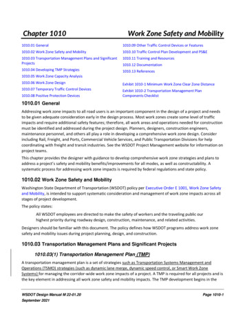
7Channelizing DevicesGROUP 136" Min.36" Min.Tubular MarkerCones4"GROUP 218" MINIMUM24" Min.6"36"36" Min.4"12"o4512" Min.Vertical PanelDrum24"12"36"4"12"36"45oDirectional IndicatorLongitudinal ChannelizingDeviceNotes:1. Flashing or steady burn warning lights and signs,when used, shall be NCHRP 350 or MASH compliant with the type of device it is mounted on.
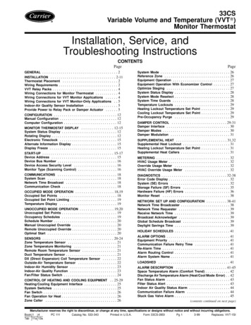
6"Channelizing Devices45 o5 ftMin.8 to12 in4 ft Min.Pass to the LeftTYPE 3 BARRICADENotes:1. Six inch wide stripes on barricade rails slopedownward at an angle of 45 degrees in the directiontraffic is to pass.2. T ype 3 barricades shall be NCHRP 350 or MASHcompliant.3. Ballast shall not be placed on top of any striped rail.4. Signs mounted on Type 3 Barricades should notcover more than the top rail.8
9Channelizing Devices (continued)Channelizing devices are used to warn and alertdrivers of hazards in work zones, to protect workers, andsafely guide and direct drivers past the hazards.Channelizing devices include cones, tubular markers,drums, vertical panels, temporary raised islands, directionalindicators, and longitudinal channelizing devices. Themost common channelizing device used in short termwork sites is the traffic cone.Traffic ConesTraffic cones shall be orange in color and a minimumof 36 inches in height. Cones used at night shall beretroreflectorized by a 6 inch band and a 4 inch bandspace 2 inches a part. Cones greater than 36" in heightshall have four alternating orange and whiteretroreflective stripes respectively 4" to 6" wide.Vertical PanelsVertical panels shall be 12 inches in width and at least24 inches in height. They shall have 6 inch orangeand white diagonal stripes and shall beretroreflectorized. Vertical panels shall be mountedwith the top a minimum of 36 inches abovethe roadway.Directional Indicators and LongitudinalChannelizing DevicesDirectional indicators and longitudinal channelizingdevices shall comply with the descriptions on Page 7.Directional indicators shall only be used in tapers.Longitudinal channelizing devices shall interlock andmay be used in place of cones or drums.
Channelizing DevicesSpacingChannelizing devices should be spaced so that they makeit apparent that the roadway or work area is closed totraffic. To accomplish this, the devices should bespaced based on the posted speed and by thefollowing guidelines:Spacing of Channelizing DevicesWork Zone LocationPosted Speed Limit SpacingIn Tapers and Curves35 mph or less20'Parallel to the Travelway35 mph or less40'Spot Construction Access*35 mph or less80'In Tapers and CurvesGreater than 35 mph40'Parallel to the TravelwayGreater than 35 mph80'Spot Construction Access*Greater than 35 mph120'* F or easier access by construction vehicles into the work area, spacingsmay be increased to this distance, but shall not exceed one access perquarter mile.DrumsPlastic drums must be a minimum of 36 inches inheight and at least 18 inches in diameter withalternating orange and white retroreflective stripes 6inches wide. Each drum shall have a minimum of twoorange and white stripes, and the top stripe shall beorange. Spacing of drums shall be the same as forcones. To ensure that the work zone is properlyprotected, drums shall be used to delineate unmannedwork areas.10
11Lighting DevicesLighting devices for short term construction,maintenance, and utility work zones are designed tosupplement the signs and channelizing devices used inthese zones. Typical lighting devices include warninglights, vehicle lights, and flashing arrow board.Warning LightsThe principal types and use of warning lights are:1. Low Intensity Flashing Lights (Type A)used to warn of an isolated hazard at night.2. High Intensity Flashing Lights (Type B)normally mounted on advance warningsigns to draw attention to a hazard bothday and night.3. Low Intensity Steady-Burn Lights (Type C)used in a series to delineate the edge of thetravelway and channelize traffic at night.4. Low Intensity 360º Steady-Burn Lights(Type D) used in a series same as type Clights when delineation is required frommultiple sides.Vehicle LightsLighting greatly enhances the visibility of workvehicles and increases their recognition factor as aslow moving hazard. Amber high intensity rotating,oscillating, or flashing lights shall be used on vehiclesperforming moving and mobile operations and onvehicles entering and exiting the work zone day andnight. Lights shall be mounted as to be viewed 360degrees. Lights shall be visible for 1/2 mile onLimited Access highways and 1500 feet on all otherroadways. White lights shall not be used.
Lighting DevicesFlashing Arrow BoardsFlashing Arrow Boards are used on vehicles in mobileoperations, and placed at the beginning of laneclosure tapers. Arrow displays shall have the followingmode selections:u flashing arrowu flashing double arrowu flashing caution (four corners)u sequential chevronArrow Board Size RequirementsTypeMin. SizeMin. No.LampsMin. LegibilityDistanceA48" x 24"121/2 mileB60" x 30"133/4 mileC96" x 48"151 mileNotes:1. Arrow Boards in the typical application diagramsshall be a Type B or C unless otherwise noted.12
13Portable Temporary Rumble Strips1.Portable Temporary Rumble Strips (PTRS) shallbe used when the following conditions are metconcurrently:a. Work operations involving flaggersoccurring on a two-lane roadway duringdaylight hours;b. Work duration of the activity at alocation is greater than three hours but lessthan 72 consecutive hours;c. Existing posted or regulatory speed limit is35 mph or greater; andd. Roadway has marked centerline(indicating at least 500 vehicles per day).2. PTRS shall be installed at the beginning of a nonstationary flagging operation; however, they willnot be required to be repositioned as the workadvances.3. PTRS shall not be used on loose gravel, bleedingasphalt, heavily rutted pavements or unpavedsurfaces, nor shall they be placed throughpedestrian crossings or marked bicycle lanes.4. PTRS are not required if the work is of emergencynature, or if the work zone is in the rain, snow, oricy weather conditions.
Portable Temporary Rumble Strips5. PTRS shall consist of three rumble strips placedperpendicular to the centerline and parallel to oneanother in accordance with the spacingrequirements in the table below. The rumble stripsshall be installed across the entire travel lane butnot intrude into the opposing travel lane. It maybe necessary to extend the PTRS onto theshoulder.6. PTRS should be:a. Considered for use on unmarked two-laneroadways at least 18 feet wide or wider.b. Located in advance of horizontal curves whenpossible so they are visible to approachingmotorists.c. Installed using Section 6G.25 Installing/Removing Temporary Traffic Control devicesof the WAPM.Spacing between each strip shall be as follows:PTRS Placement ChartPosted/Statutory Speed Limit PTRS Spacing (Center to Center)10 Feet15 Feet20 Feet 40 mph40 mph 50 mphWhen traffic queues prior to the PTRS, the PTRSand rumble strip signs may need to be relocated inadvanced of the queue to better serve as a warningdevice to motorists.14
15Shadow Vehicles shadow vehicle (see Truck MountedAAttenuators) shall be placed 80’ to120’ in advanceof the first work crew encountered by travelingmotorists. A shadow vehicle should be used wheninstalling and removing TTC devices and be placed80’ to 120’ in advance of the each work crew. Eachshadow vehicle shall have at least one amber highintensity rotating, oscillating, or flashing lightfunctioning while in operation. A work vehicleshall be used to store, install and remove TTCdevices.Truck Mounted AttenuatorsA shadow vehicle requires a truck or trailer mountedattenuator (TMA) in all lane and/or partial rampclosures on four or more lane roadways when theposted speed limit is 45 mph or greater, and for mobileoperations which fully or partially block a lane onroadways posted 45 mph or greater. All TMA unitsshall conform to the requirements of NCHRP 350 Test Level 3 or MASH regardless of where the unitwill be used.Placement of shadow vehicle with the TMA shallbe 80' to 120' in front of the first work crew,equipment, or hazard encountered by travelingmotorists. A shadow vehicle should be placed 80’ to120’ in advance of the each work crew. Each TMAvehicle shall have at least one amber high intensityrotating, oscillating, or flashing light functioningwhile in operation.
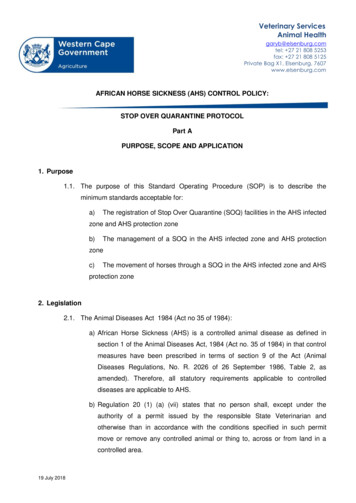
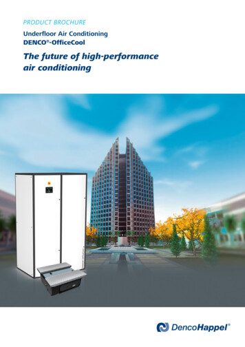
Component Parts of a TemporaryTraffic Control ZoneTERMINATION AREAlets traffic resumenormal K SPACEBUFFER AREAprovides protection fortraffic and workersTRANSITION AREAmoves traffic outof its normal pathADVANCEDWARNING AREAtells traffic whatto expect ahead16
17Five Parts of a TemporaryTraffic Control ZoneThe temporary traffic control zone is the distancebetween the first advance warning sign and the pointbeyond the work area where the traffic is no longeraffected. Above is a diagram showing the five parts ofa temporary traffic control zone.Buffer AreaThe length of a longitudinal buffer is determined bythe posted speed limit and should be as shown in thechart below.Length of the Longitudinal Buffer AreaPosted Speed (MPH)Distance (Feet)20253035404550556065707515 - 120155 - 165200 - 210250 - 260305 - 325360 - 380425 - 445500 - 530570 - 600645 - 675730 - 760820 - 850
Taper Length Criteria for Work ZonesThere are five types of tapers used in work zonetraffic control. The length of each type of taper isbased on the speed of traffic and the width of theoffset (or lane width). The following are the five typesof tapers and their lengths.Type of TaperTaper LengthMergingShiftingShoulderTwo-wayDownstreamL MinimumSee Table Below1/3 L Minimum50 to 100 Ft.50 Ft. Min. to 100 Ft. Max.Taper Length (L)Speed (S)in MPH25 or belowWidth of Offset (W) in Ft.910111295105115125RemarksL S2 5405450495540L 85650715780"70630700770840“Limited Access Highways shall use a 1000’ merging taperregardless of the speed limit.Shifting Tapers—full lane width shifts on Limited AccessHighways shall use a 750’ shifting taper for posted speedsless than 65 mph and a 1000’ shifting taper for postedspeeds equal to or greater than 65 mph. For all otherroadways, 3/4 L should be used.18
19Types of Tapers and Buffer SpacesFour AdditionalChannelizing DevicesLMergingTaperLongitudinalBuffer Space3/4 LDownstreamTaperShiftingTaperLateral BufferSpace(optional)WorkSpaceLongitudinalBuffer Space3/4 LShiftingTaperFour AdditionalChannelizing DevicesShifting 3/4 LTaperLateral BufferSpace(optional)LongitudinalBuffer Space1/3 LShoulderTaper
Work Zone Applications inCurves and HillsFLAGGERDOWNSTREAM TAPER50' TO 100'BUFFER SPACE(LONGITUDINAL)WORK AREABUFFER SPACE (LONGITUDINAL)IS USED TO POSITION THE TAPERIN ADVANCE OF THE CURVEONE-LANE,TWO-WAY TRAFFIC TAPER50 – 100 FEETFLAGGER*REFER TO THE“TYPICAL APPLICATION DIAGRAMS”FOR CORRECT INSTALLATION OFTRAFFIC CONTROL DEVICES.20
21Work Zone Applications inCurves and HillsWhen the work activity occurs in a curve or the downside of a hill, consideration should be given to theplacement of the advanced warning devices. It’salways best to place the warning signs, arrow board,and taper devices in a tangent section of roadway formaximum visibility. This may involve extending thelane closure and increasing the buffer space toaccomplish. If the lane closure cannot be lengtheneddue to roadway constraints, then the length of thetaper should increase to provide additional merge areafor vehicles. On hills, the signs, taper, arrow boardand flagger stations should be seen prior to reachingthe crest of the hill.Installing/Removing Lane ClosuresCare must be exercised when installing and removinglane closures. All stationary lane closures begin andend as mobile operations. TTC devices shall not bestored, installed or removed from a shadow vehicle.All TTC devices shall be stored, installed or removedfrom a work operation vehicle. The traffic controlneeded to perform the operation safely is dictated bythe location on the roadway the mobile operation willoccur; either on the shoulder or partially or fully inthe lane. A shadow vehicle with a TMA shall be usedto protect workers and their work vehicle during theinstallation and removal of TTC devices.
Installing Lane ClosuresStationary lane closures should be installed with theflow of traffic in the following sequence:1. Install all advance warning signs.2. Install shoulder taper if necessary.3. Place arrow board on the shoulder at the beginningof the merging taper.4. Install channelizing devices to form a mergingtaper.5. Install channelizing devices along the buffer space.6. Continue placing channelizing devices along the workarea at the appropriate spacing.7. Install channelizing devices for the terminationarea.8. Install the “END ROAD WORK” signapproximately 500' beyond the last device in thelane closure.9. Place a TMA vehicle, if required, 80'-120' fromfirst work crew or hazard approached by motorists.A “ride through” through the entire lane closure shouldbe performed (with adjustments made to the trafficcontrol devices if needed) to ensure that the laneclosure is installed and functioning properly. Majoradjustments to the work zone should be documented.22
23Removing Lane ClosuresStationary lane closures should be removed againstthe flow of traffic in the following sequence:1. Remove channelizing devices from end of closureback to the widest part of the merging taper.2. Place removal vehicle on shoulder and removedevices from taper by hand onto the work vehicle.3. Remove arrow board after ensuring roadwayis clear.4. Moving with the flow of traffic, remove all of theadvance warning signs beginning with the “ROADWORK AHEAD” sign and ending with the “ENDROAD WORK” sign.Use of a TMA vehicle when installing and removinglane closures on multi-lane roadways increases thesafety of the operation for both the worker and thetraveling public, and shall be used whenever theshoulder width prevents these operations from beingperformed completely off of the travelway. When Atrailer mounted TMA is used on the shadow vehicle,all devices may be removed with the flow of traffic.Workers running across an open travel lanes of trafficto install and remove TTC devices is a dangerouspractice and should not be performed unless slow rolltemporary traffic control operations are beingperformed (see Sections 6G.24 and 6G.25, as well asTTC-62 in the Virginia Work Area Protection Manual).
DefinitionsThe following are several important definitions forterms used in these guidelines. These definitions weredeveloped to aid the supervisor at the job site indetermining the appropriate traffic control for theexisting street or highway conditions.If the traffic conditions or work status changes duringthe course of the work, then the traffic control mustchange also.Low SpeedAs a general rule, a low speed road can beconsidered one on which the posted speed is less than45 miles per hour (MPH).Low VolumeAs a general rule, a low volume road can beconsidered one which the average daily traffic (ADT)volume does not exceed 500 vehicles per day. If thetraffic volumes are not known, the following rule ofthumb can be used to determine if the road can betreated as low volume for the purposes of installing workzone traffic control:Count the number of vehicles that pass asingle reference point over a five minute period.If no more than 3 vehicles pass the referencepoint in that period, then the road can beconsidered low volume.24
25Definitions (continued)The following are categories of work duration andtheir time at a location:Mobile OperationWork that moves intermittently or continuously (0-15minutes) and does not occupy the immediate area formore than 15 minutes. The immediate area istypically defined as a 1000 linear foot distance.Short DurationOccupies a location from 15 minutes to 1 hour.Short-term StationaryOccupies a location for more than 1 hour but less than12 hours within a single daylight period.Intermediate-term stationaryOccupies a location more than one daylight periodup to 3 days, or nighttime work lasting more than1 hour.Long Term StationaryOccupies a location longer than 3 days (72consecutive hours).Nighttime ActivitiesTraffic control should be installed for nighttimeoperations from 30 minutes before sunset to 30minutes after sunrise.
Typical Application DiagramsThe diagrams on the following pages representexamples of the application of principles andprocedures for safe and efficient traffic control intemporary traffic control zones and are not intended tobe standards. It is not possible to include illustrationsto cover every situation that requires temporary trafficcontrol. These typical layouts are not intended as asubstitute for engineering judgement and should bealtered to fit the conditions of a particular site.The information presented in these diagrams areminimums for standard highway (non-Limited Access)conditions with posted speeds of 55 mph or less. Forurban conditions (a low speed, two-lane street locatedinside a municipality's corporate limit) shorter spacingsand lengths may be required. Limited Access highwayconditions will require longer distances. For furtherinformation, refer to the Virginia Work AreaProtection Manual; the standard for temporary trafficcontrol in the Commonwealth of Virginia.LegendChannelizing DeviceFlaggerPortable Sign SupportWarning SignFlashing Arrow BoardWork AreaFlashing LightTMA VehicleTravel DirectionShadow VehiclePortable TemporaryRumble Strip26
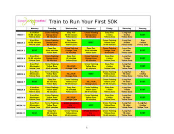
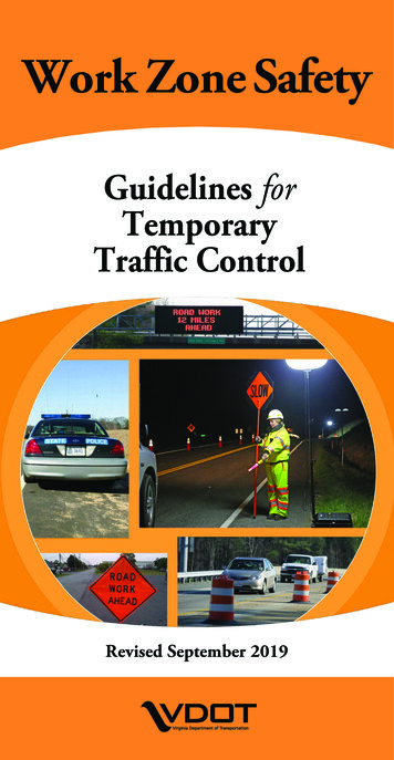
27Work Outside the Shoulder(15' or More From the Edge of Travel Way)SEENOTE 1DITCHLINESEE NOTE 3
Work Outside the ShoulderNotes:1. If vehicle and work activity are both outside theright-of-way, behind the guardrail or barrier, morethan 4' behind vertical curb on urban roadways, oroutside the clear zone for all other roadways, thenonly an activated amber high intensity rotating,oscillating, or flashing light is needed.2. A n advance warning sign should be used: if thework will be performed immediately adjacent to theshoulder, if equipment will cross or move along theroadway, or if the activity may distract motorists.3. Sign spacing: limited access 1300' - 1500'; postedspeed greater than 45 mph 500' – 800'; postedspeed 45 mph or less 350' – 500'; see spacing ofsigns for urban use on page 6.4. Other acceptable advance warning signs are thoseindicating shoulder work or utility work ahead.28
29Permitted Temporary EntranceTRUCKSENTERINGHIGHWAYSEE NOTE 3PERMITTEDTEMPORARYENTRANCESEE NOTE 3TRUCKSENTERINGHIGHWAY
Permitted Temporary EntranceNotes:1. Notify the appropriate state or local agencies priorto the installation of the entrance and placement ofany traffic control devices.2. The organization receiving the entrance permit isresponsible for removal of all debris (gravel, mud,dust, hauled materials, etc.), obstructions andirregularities caused by the operation. A flaggingoperation is required for removing debris on atwo-lane roadway. A mobile operation isrequired to remove debris on a multi-laneroadway.3. Sign spacing: posted speed greater than 45 mph500' – 800'; posted speed 45 mph or less 350' –500'; see spacing of signs for urban use on page 6.30
31Shoulder WorkMobile or Short Duration Operation(60 Minutes or less in the Intermediate Area)80’-120’WORKVEHICLE REQUIREDSEE NOTE 2ILLUMINATED FLASHINGAMBER (CAUTION MODE)TYPE B OR C84” x 36”
Shoulder WorkMobile or Short Duration OperationNotes:1. The first shadow vehicle may be replaced with a48"x 48" “ROAD WORK AHEAD” or“UTILITY WORK AHEAD” sign.2. The minimum distance between sign and shadowvehicle should be 350'-500' where the posted speedlimit is 45 mph or less, and 500'-800' where theposted speed limit is greater than 45 mph. Themaximum distance between sign and work vehicleis 2 miles.3. Each shadow vehicle involved in the operation shallhave at least an arrow board operating in thecaution mode or at least one amber high intensityrotating, oscillating, or flashing light.4. When the work operation is off the shoulder witha work duration of 15-60 minutes, vehicle warninglights and a truck mounted sign (W20-V3,W20-V6, W20-V1, etc.) or a sign on a portablesign support shall be placed behind the workoperations vehicle.5. The work area may be delineate by installingchannelizing devices.32
33Shoulder Work Stationary Operation(Greater Than 60 Minutes in the Immediate Area)500'80'-120'SHADOW VEHICLEREQUIRED(TMA OPTIONALSEE NOTE 6)BUFFERSEE NOTE 31/3 L TAPERSEE NOTE 2RIGHTSHOULDERCLOSEDSEE NOTE 2SEE NOTE 2
Shoulder Work Stationary OperationNotes:1. F or operations less than 3 days in duration, signassemblies will only be required on the side wherethe shoulder is being closed (as shown). For longterm stationary work (more than 3 days) ondivided roadways having a median wider than 8',sign assemblies on both sides of the roadway shallbe required (ROAD WORK AHEAD andRIGHT SHOULDER CLOSED AHEAD).2. S ign spacing: limited access 1300' - 1500'; postedspeed greater than 45 mph 500' – 800'; postedspeed 45 mph or less 350' – 500'; see spacing ofsigns for urban use on page 6.3. F or length of the buffer space, see Buffer SpaceLength Chart on page 17.4. A vehicle with at least one amber high intensityrotating, oscillating, or flashing light shall beparked 80'-120' in advance of the first work crew.5. A “UTILITY WORK AHEAD” sign may be usedin place of the “ROAD WORK AHEAD”.6. A truck/trailer-mounted attenuator (TMA) shallbe used on the shadow vehicle on Limited Accesshighways and multi-lane roadways with a postedspeed limit equal to or greater than 45 mph.7. For channelizing device spacing, see Spacing forChannelizing Chart on page 10.34
35Shoulder Work With MinorEncroachment - Stationary Operation500'10'MIN.80'-120'SHADOW VEHICLEREQUIRED(TMA OPTIONALSEE NOTE 7)BUFFERSEE NOTE 31/3 L TAPERSEE NOTE 2SEE NOTE 2
Shoulder Work With MinorEncroachment - Stationary OperationNotes:1. On divided roadways having a median wider than8', left and right sign assemblies shall be required.2. Sign spacing: limited access 1300' - 1500'; postedspeed greater than 45 mph 500' – 800'; posted speed45 mph or less 350' – 500'; see spacing of signs forurban use on page 6.3. F or length of the buffer space, see Buffer SpaceLength Chart on page 17.4. A vehicle with at least one amber high intensityrotating, oscillating, or flashing light shall be parked80'-120' in advance of the first work crew.5. A “UTILITY WORK AHEAD” sign may be usedin place of the “ROAD WORK AHEAD”.6. Lane widths less than the 10 foot minimum must beapproved by the District Traffic Engineer.7. A truck/trailer-mounted attenuator (TMA) shall beused on the shadow vehicle on Limited Accesshighways and multi-lane roadways with a postedspeed limit equal to or greater than 45 mph.8. For channelizing device spacing, see Spacing forChannelizing Chart on page 10.36
37Four-lane Road Mobile Operation(15 Minutes or Less in the Immediate Area)WORK OPERATIONSVEHICLESEE NOTE 31000'84" x 36"84" x 36"(SEE NOTE 2)
Four-lane Road Mobile OperationNotes:1. Each vehicle involved in the mobile operation shallbe equipped with at least one amber high intensityrotating, oscillating, or flashing light. All vehiclesshown shall have an arrow panel operating in theflashing arrow mode.2. If the shadow vehicle occupies any part of thetravel lane, it shall have a TMA.3. When the work operations vehicle is stationary, theTMA vehicle shall be in a position 80' – 120' inadvance of the work operations vehicle. When thework operations vehicle is moving, the TMAvehicle shall follow at a distance of 240' .4. The static warning sign and arrow board may bereplaced with a vehicle mounted changeable messagesign (CMS) with a minimum of 10" height characters.5. On Limited Access highways an additional TMAvehicle (not shown) is required. Shadow vehicle1 is on the shoulder, TMA vehicle 2 straddles theedge line and TMA vehicle 3 are in the closedlane.38
39Four-lane Road - Non LimitedAccess Short Duration Operation(16 Minutes to 60 Minutes in the Immediate Area)80'-120'84" x 36"SEE NOTE 2
Four-lane Road - Non LimitedAccess Short Duration OperationNotes:1. E ach vehicle involved in the mobile operation shallbe equipped with at least one amber high intensityrotating, oscillating, or flashing light. All vehiclesshown shall have an arrow board operating in theflashing arrow mode.2. Minimum distance between sign/shadow vehicleand the TMA vehicle should be 350'-500' wherethe posted speed is 45 mph or less, and 500'-800'where the posted speed is greater than 45 mph.3. The shadow vehicle on the shoulder may bereplaced with a “ROAD WORK AHEAD” signon low speed, low volume roadways. If the shadowvehicle
Urban Streets with 30 to 40 mph posted speed limit. 250' - 350' *All Other Roadways with 45 mph or less posted speed limit. 350' - 500' All Other Roadways with greater than 45 mph posted speed limit. 500' - 800' Limited Access Highways 1300' - 1500' *Urban streets with greater than 40 mph posted speed limits fall into this category. Removal of .