Transcription
GE - ECM Motor Technologyand TroubleshootingPresented by The RLCS EngineeringProduct Field Support
Airflow If SPEED is constant, CFM changes withStatic Pressure To hold CFM constant, SPEED mustchange with Static Pressure
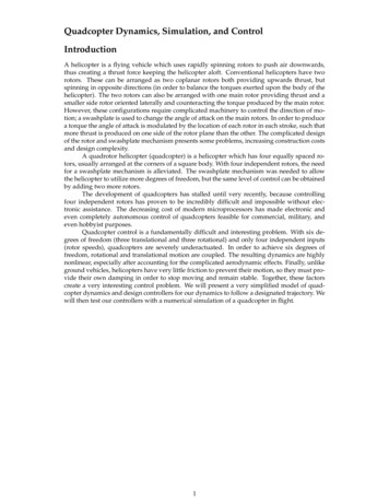
Unregulated Versus Regulated AirflowNo System Balancing Required!Set the airflow leveland go!0.80.7PRESSURE0.6System airflow is flow (CFM)190020002100220023002400Overblowing the system poor moisture removal high power consumption
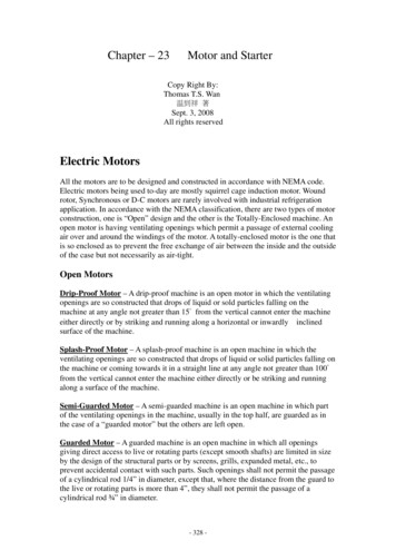
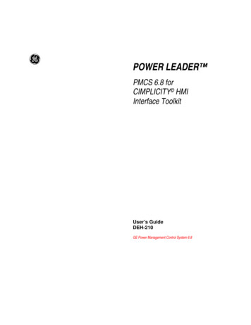
The ECM’s Benefits in HVACECMAirflow Control„ Constant airflow over wide external pressure changes„ Greater customer comfort and satisfactionPSC„ External pressure change causes:„ airflow variation as filter loads„ reduced performance„ poor latent/sensible capacity controlAir Volume vs Ext SPCu Ft/min1-ph PSC Lo1-ph PSC Med1-ph PSC .8Ext Static Pressure (" H2O)1.0ECM
What's an ECM ?The highest efficiency motor there is! A DC Motor„ Without mechanical Brushes and Commutator„ Permanent Magnet Rotor„ Rotor losses are nearly zero„ Stator is driven from an Inverter which,in turn, is powered from the AC line„ The “Electronic Inverter”„ “Commutates” the stator magnetic fields„ Synchronous machine„ Speed and torque controlled„ Interfaces to the HVAC controls
ECM Issues - Furnaces / Fancoils Prior to potted controls:– Moisture was responsible for most failures The Power Transistors were the most commonfailure Contaminants from the air, added to themoisture/condensation, were also a concern Now, most common failure:– NO defects found
ECM 2.3 - Potted Control Produced in fan coilsand Tyler productssince October 1998 Produced in furnacessince September 1999
Types of ECM Control Thermostatically Controlled– Fan Coils / Non-condensing furnaces /Packaged Units Pulse Width Modulation (PWM)– Split systems (A/C & Heat Pump)– Condensing Furnaces
Thermostatically Control ECM logic for fan coils, non-condensingfurnaces and Tyler products– Uses Full, Half, Positive, Negative or No Sinewave– Bases CFM on predetermined CFM curves Models programmed differently– CFM is controlled by adjusting torque in responseto RPM– RPM is sensed by the motor’s “back EMF”– Always uses the “highest CFM” of what is beingcalled for
FAN COIL EASY SELECT BOARDDH - DehumidificationR - 24 VACW1 - 1st stage Elect HtW2 - 2nd stage Elect HtY1 - 1st stage CompressorYY/2 - 2nd stage Compressoror single stage CompressorG - FanO - Reversing Valve in ClgC - CommonHum - Humidifier (24VAC)AUX - Auxiliary (24VAC)EAC
ECM LogicPulse WidthModulationPWM
Pulse Width Modulation(PWM) PWM is a simple way of commandingairflow (CFM), as defined from an externaldevice (2 wire method) The variable speed circuit board suppliesthis signal to the motors
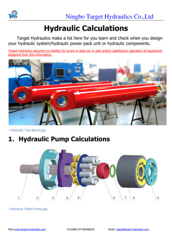
90% ECM MOTORTECHNOLOGY “PWM”Pulse WidthModulation (PWM)Equation determinesthe slope of the curveBased on duty cycleCFM 2CFM 1MinPWMMaxPWM
Duty CycleVoltage (dc)The amount of “ON-TIME” per cyclePWM A/B or PWM% A/B% (a b full speed,emergency heat, sw 4 - on)ABTime
ECM logic for variable speedcondensing gas furnaces Furnace control board sends a PWM signalto the motor Control logic is contained in the Furnacecontrol board– Airflow is determined by the model or“personality plug” on furnace board PWM can be read by an oscilloscope– will be seen as a square waveform
38TDA/YDA, 598WCondensing Units Uses logic in Circuit Board of outdoor unit– Control Board sends a PWM signal to themotor– Signal can be read with a “DC” volt meter, withmotor at full speed (22º OAT 90º) at PW1,PW2 16-20 VDC with motor connected 20-40 VDC with motor Disconnected
Control Board Setups
FAN COIL EASY SELECT BOARDDH - DehumidificationR - 24 VACW1 - 1st stage Elect HtW2 - 2nd stage Elect HtY1 - 1st stage CompressorYY/2 - 2nd stage Compressoror single stage CompressorG - FanO - Reversing Valve in ClgC - CommonHum - Humidifier (24VAC)AUX - Auxiliary (24VAC)EAC
FK4C Fan Coil Size 002 3 ton Heat Pump 15 KW electric Heat Setup
Easy Select Board
Easy Select BoardHP-COMFORTLO CFMENH DELAY
Easy Select Board Remove J1 jumper toactivate dehumidifymode Remove J2 jumper toseparate W1 & W2(Intelligent Heatstaging)
ECM setup for Variable SpeedCondensing Gas Furnace2 Sets of three (3) field selectable dip switch banks,Model Plug, and Thermostat inputs determine airflow.Status & Diagnosis LED’sContinuous Fan (CF)A/C SetupFurnace Test, Blower, & DelayModel Plug
MVP furnace Board Setup(changes made in idle mode)
80% Variable Speed ControlBoard
Tyler Packaged Units
ECM Troubleshooting
ECM Troubleshooting All troubleshooting information can befound in Service Manuals Fan Coil (catalog# 03FA-5A0) Mid-efficiency furnace (catalog# 535-800) Infinity furnace (catalog# 565-829) ECM Troubleshooting Guide / Tylerproducts (catalog# 534-897)
All ECM Motors Slight “cogging” or rocking is inherent to all ECMmotors– motor is finding its location between stator and rotor and isdetermining rotation “Rumbling” sound during startup and shutdown– System mechanical resonance (approx 300-400rpm), three(3) permanent magnets (stators) cause the rotor to have a“rumble” during low RPM’s “Fixes”– Don’t replace motor!– Isolate sound: Canvas duct connectors, rubber grommets,etc.
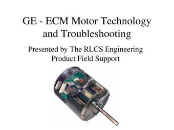
Power PlugsHigh Voltage5 PIN CONNECTORLow Voltage16 PIN CONNECTOR
ECM Warning !!!NEVER remove or connect the 5 PIN HIGHVOLTAGE CONNECTOR of the motor, withthe power ON !!- High Voltage is always present at the motor- Arcing could damage electronics.
ECM warning!!! ECM motors should NOT be testedUNLESS under LOAD– Erratic motor behavior could occur withouta load (static pressure)
High Voltage Power Connector
Troubleshooting ECM MotorsCheck HIGH VOLTAGE at motorPins 4, 5 of five pin connectorSHOULD ALWAYS HAVE HIGH VOLTAGE120 Volts for furnaces240 Volts for fan coils / Tyler products
Low Voltage Connector
Troubleshooting ECM MotorsCheck LOW VOLTAGE at the motorPins 1(C), 12(R) of sixteen pin connectorSHOULD ALWAYS HAVE 24VAC VOLTAGE AT THEMOTORIf not, check for voltage at circuit board
ECM Motor shaft turns,but not smoothlyIf the shaft (with blower wheel disconnected) isdifficult to turn with the motor control attached:- and turns freely with the control disconnected,then the control is damaged.- and does not turn free with the controldisconnected, then the motor is damaged. Verifycontinuity of windings (motor leads to unpaintedmotor end plate). They should be 100KW.
ECM Motor won’t stoprunning Check for good ground between––––motor groundtransformer common leadThermostat wiringControl Board Remove 12 pin connector, if motor stops it’s controlwiring. If it continues to run, motor is bad.
Replacement Issues Insert Blower motor as far into cradle as possible– air over motor helps keep motor cool Verify proper installation of motor to preventwater entering pin connections– Drip legs, proper positioning Beware of electronic thermostats (90% furnaces)– units that notch the waveforms– “Power-Stealing”
Notes on Mounting and OrientationA Few Factors Are Critical When mounting Motor/Control Condensate or droplets can accumulate in harness Orient connectors "down" whenever possible "Drip Loops" are important!Motor Mounting to Blower Can Control Noise Loose blower wheel on shaft can affect starting and will be noisy Loose motor in mount or loose attachment to housing will cause noiseand poor starting
RCD - Fan Coil ReplacementModules
RCD - Furnace ReplacementsModule
Pulse Width Modulation (PWM)Troubleshooting
Infinity Troubleshooting Guide Example: Inducer Motor– Use Troubleshooting Guide– Check voltages Line, PW and Feedback voltages
Infinity Inducer Motor Power / high voltage– pins 6 & 12 PW voltage– pins 2 & 10 Feedback voltage– pins 2 & 1– pin 4 /ground
Advanced Product Monitor(APM) APM kit will help troubleshoot the furnace,including the ECM motors Requires:– Laptop– Software– B&B RS485 Adapter
ECM Motor Simulator(for HK42FZ003 /012 Only)1. Shut off power to the unit2. Disconnect PL13 and plug it into the ECMMotor Simulator3. Turn power on to unit4. Put setup switch SW-6 to the “ON”position5. Observe fault code displayed
Thermostatic ECMTroubleshooting
Troubleshooting ECM MotorsCall for W1, check LOW VOLTAGEpins 1, 2 of sixteen pin connectorCall for W2, check pins 1, 13(SHOULD HAVE 24VAC)
Troubleshooting ECM Motors forFan CoilsCheck LOWVOLTAGE at R andC, at the controlboardPins 8, 9 of twelve pinconnector(SHOULD HAVE 24VAC)
FAN COIL PINS @ CIRCUIT BOARDCHECK W1, Y/Y2, Y1 (USES 24VAC)AUX/HEAT KW/CFM, AC/HP SIZE, SYSTEM TYPE, AC/HP ADJUST, ON/OFFDELAY, CONTINUOUS FAN (Uses Half Wave Signals)Operating ModeElectric Heating1-Speed A/C, Cooling2-Speed A/C, Low Cooling2-Speed A/C, High Cooling1-Speed HP, Cooling2-Speed HP, Low Cooling2-Speed HP, High Cooling1-Speed HP, Heating2-Speed HP, Low Heating2-Speed HP, High Heating1-Speed HP, Heating2-Speed HP, Low Heating2-Speed HP, High HeatingContinuous Fan- LoContinuous Fan- MedContinuous Fan- HiThermostat Inputhaving 24VAC W1, Pin 7 C, Pin R,Y1,Y/Y2,G00R,Y/Y2,G, W124VAC0R,Y1,G, W124VAC0R,Y1,Y/Y2,G, W1 24VAC0R,G00R,G00R,G00R, Pin 8 Y/Y2, Pin 2 Y1, Pin 12VDC24VAC-12VDC-12VDC24VAC0024VAC0 -12VDC'24VAC -12VDC''''0
Newest FK4C installationinstructions New instructions have more troubleshootingtables and examples Form # IM-FK4C-07 Catalog# 63FK-4C3
JumperWirePin 9Pin 2-12vdc-12vdc
JumperWirePin 4Pin 224vac24vac
Other Contributing Factors Fan coils are a“DrawThru” design If not properly trapped,the water will hold indrain pan Water could drip on motorin downflow application Make trap IS DONECORRECTLY!!
Troubleshooting ECM Motors for80% two speed furnacesCheck LOW VOLTAGE at R-C terminals, at the control boardPins 14, 9 of fourteen pin connectorSHOULD ALWAYS HAVE 24VAC
80% 2 SPEED FURNACE PINS ATEASY SELECT CIRCUIT BOARDCheck W1, W2, Y/Y2, Y1 (Uses 24VAC)AUX/HEAT KW/CFM, AC/HP SIZE, SYSTEM TYPE, AC/HP ADJUST, ON/OFFDELAY, CONTINUOUS FAN (Uses Half Wave Signals)Operating Mode1-Speed A/C, Cooling2-Speed A/C, Low Cooling2-Speed A/C, High Cooling1-Speed HP, Cooling2-Speed HP, Low Cooling2-Speed HP, High Cooling1-Speed HP, Heating2-Speed HP, Low Heating2-Speed HP, High HeatingLow Fire, HeatingHigh Fire, HeatingThermostatInput havingW,W1,24VACPin ,O0R,Y1,Y/Y2,G,O0R,Y/Y2,G0R,Y1,G0R,Y1,Y/Y2,G0R,G, W124VACR,G, W1, W224VACW2, PinPL4-4000000000024VACC, Pin C, PinPL7-9 PL7-80000000000000000000000R, 4VAC24VAC24VACY/Y2, WITH 16 PIN MOTOR CONNECTOR DISCONNECTED)Y1, VDC0
Troubleshooting ECM Motors forTyler ProductsCHECK LOWVOLTAGE R-C AT THECONTROL BOARDPINS PL2-5, PL2-3 OF 7PIN CONNECTORSHOULD ALWAYSHAVE 24VAC
TYLER PRODUCT PINSAT CIRCUIT BOARDCHECK W1, G, Y/Y2, Y1 (USES 24VAC)AUX/HEAT KW/CFM, AC/HP SIZE, SYSTEM TYPE, AC/HP ADJUST, ON/OFFDELAY, CONTINUOUS FAN (Uses Half Wave Signals)Unit & Operating ModeElectric & Heating1-Speed A/C Cooling2-Speed A/C Low Cooling2-Speed A/C High Cooling1-Speed HP Cooling1-Speed HP Heating2-Speed HP Low Cooling2-Speed HP Low Heating2-Speed HP High Cooling2-Speed HP High HeatingContinous FanThermostat Input W, Pin G, PinC, Pinhaving 24VACPL2-1PL2-2PL2-3R,W2,W3,E24VAC 024VAC0C, PinPL2-400000000000R, PinY/Y2, Pin Y1, PinPL2-5PL2-6PL2-724VAC0024VAC 24VAC024VAC024VAC24VAC 24VAC024VAC 24VAC024VAC 24VAC024VAC024VAC24VAC024VAC24VAC 24VAC 24VAC24VAC 24VAC 24VAC24VAC00(WITH 16 PIN MOTOR CONNECTOR DISCONNECTED)
Proper Ductwork Installation Check existing ductwork static pressure Determine existing equipment CFM Use Product Data Sheet to determine thatnew equipment will work with existingductwork or if it will require ductworkmodifications– See following examples
Condensing FurnaceFan Performance ECM Motor’s RPMrange is 250-1300rpm Outside of this range,a Status Code 44 willoccur– High fire will defaultto 1200rpm– cooling- last validPWM
Fan Coil Fan Performance Performance capableof 0.9” w.c. in someapplications– Torque”cad-back” willlimit RPM– Oscillation can occurduring high static Nominal 350cfm/ton Airflow can beadjusted 15%or -10%
Additional Fan CoilConsideration Return and Supplystatic must be in“white area” toprevent condensateremoval from drainpan
Other things to consider An ECM motor will out-perform a PSCmotor in high static situations– Condensing furnace will display a fault code(above 1300rpm’s) but still provide more CFMthan standard PSC motor at comparableexternal static pressure– Thermostatically Controlled motors willprovide desired CFM in high static situations
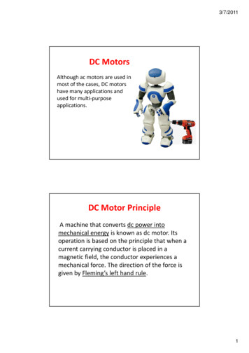
The ECM’s Benefits in HVAC ECM Airflow Control PSC Air Volume vs Ext SP 900 1000 1100 1200 1300 1400 1500 1600 1700 0.0 0.2 0.4 0.6 0.8 1.0 Ext Static Pr