Transcription
MachinistHandbookMachining Plastics Made EasyBR O U GH TTO Y O U B Y:8 0 0 -8 7 7 -2 5 7 6A L R OP L A ST I CS .C OM1
Broad Inventory Offering: Engineering Plastic Rods from 1/8” to 18” diameter Engineering Plastic Sheets from 1/8” to 8” thickYour Source for Engineering Plastics: Over 20 million in stock at Alro Plastics Same day cutting and shipping for quick delivery In-House CAD Department2
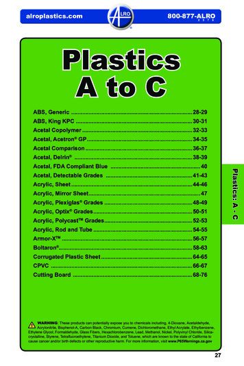
Table of Contents041012141618202223242628323436Fabrication GuidelinesMachinabilityDrilling GuidelinesTroubleshooting - DrillingSawing GuidelinesEnd Milling/ Slotting GuidelinesFace MillingTroubleshooting - Tur ning & BoringTroubleshooting - Cutting OffTur ning GuidelinesAnnealingAir Annealing GuidelinesDiagramsConversionsNotesPlease Return Phone:Email:3
FA B R I C ATION GU IDELINESThe following guidelines are presentedfor those machinists not familiar with themachining characteristics of plastics. Theyare intended as guidelines only and maynot represent the most optimum conditionsfor all parts. The troubleshooting quickreference guides in this booklet should beused to correct undesirable surface finishesor material responses during machiningoperations.4All Mitsubishi Chemical Advanced Materialsare stress relieved to ensure highest degreeof machinability and dimensional stability.However, the relative softness of plastics(compared to metals) generally results ingreater difficulty maintaining tight tolerancesduring and after machining. A good rule ofthumb for tolerances of plastic parts is /.001 per inch of dimension although tightertolerances are possible with very stable,reinforced materials.When Machining MitsubishiChemical Advanced MaterialsStock Shapes Remember.Getting Started T hermal expansion is up to 10x greaterwith plastics than metals Carbide tooling with ground top surfacesis suggested for optimum tool life andsurfaces finish. Polycrystalline diamondtooling provides optimum surface finishwhen machining Duratron PBI. P lastics lose heat more slowly thanmetals, so avoid localized overheating S oftening (and melting) temperaturesof plastics are much lower than metals P lastics are much more elastic thanmetalsBecause of these differences, you maywish to experiment with fixtures, toolmaterials, angles, speeds and feed ratesto obtain optimum results. P ositive tool geometries with groundperipheries are recommended U se adequate chip clearance to preventclogging A dequately support the material torestrict deflection away from thecutting tool
CoolantsMachining TipsCoolants are generally not required formost machining operations (not includingdrilling and parting off). However, foroptimum surface finishes and closetolerances, non-aromatic, water solublecoolants are suggested. Spray mists andpressurized air are very effective means ofcooling the cutting interface. Generalpurpose petroleum based cutting fluids,although suitable for many metals andplastics, may contribute to stress crackingof amorphous plastics such as Altron PC1000, Sultron PSU, Duratron U1000 PEI,and Sultron PPSU.Coolants are strongly suggested duringdrilling operations, especially with notchsensitive materials such as Ertalyte PET-P,Duratron PAI, Duratron PBI and glass orcarbon reinforced products.In addition to minimizing localized partheat-up, coolants prolong tool life. Two(flood) coolants suitable for most plasticsare Trim E190 and Trim Sol LC SF (MasterChemical Corporation – Perrysburg, OH).5
FA B R I C ATION GU IDELINESThreading & TappingMillingThreading should be done by single pointusing a carbide insert and taking four tofive 0.001 passes at the end. Coolantusage is suggested.Sufficient fixuring allows fast table traveland high spindle speeds when end millingplastics. When face milling, use positivegeometry cutter bodies.For tapping, use the specified drill with atwo flute tap. Remember to keep the tapclean of chip build-up. Use of a coolantduring tapping is also suggested.SawingUse of a coated tap can improve thetoughness of threads in a notch sensitivematerial.6Band sawing is versatile for straight,continuous curves or irregular cuts. Tablesaws are convenient for straight cuts andcan be used to cut multiple thicknessesand thicker cross sections up to 4 withadequate horsepower. Saw blades shouldbe selected based upon material thicknessand surface finish desired.
Sawing Tips R ip and combination blades with a 0ºtooth rake and 3º to 10º tooth set arebest for general sawing in order toreduce frictional heat. H ollow ground circular saw bladeswithout set will yield smooth cuts upto 3/4 thickness. T ungsten carbide blades wear welland provide optimum surface finishes.7
DR I LL I NGThe insulating characteristics of plasticsrequire consideration during drillingoperations, especially when hole depthsare greater than twice the diameter.Small diameter holes (1/32 to1 diameter)High speed steel twist drills are generallysufficient for small holes. To improve swarfremoval, frequent pulling out (peck drilling)is suggested. A slow spiral (low helix) drillwill allow for better swarf removal.Large diameter holes (1 diameter & larger)8A slow spiral (low helix) drill or generalpurpose drill bit ground to 118º pointangle with 9º to 15º lip clearance isrecommended. The lip rake should beground (dubbed off) and the web thinned.It is generally best to drill a pilot hole(maximum 1/2 diameter) using 600 to1,000 rpm and a positive feed of 0.005 to0.015 per revolution. Avoid hand feeingbecause of the drill grabbing which canresult in microcracks forming. Secondarydrilling at 400 to 500 rpm at 0.008 to 0.020 per revolution is required to expand thehole to larger diameters.A two step process using both drillingand boring can be use on notch sensitivematerials such as Ertalyte PET-P and glassreinforced materials. This minimizes heatbuild-up and reduces the risk of cracking.Tech Tip: 1. D rill a 1 diameter hole using aninsert drill at 500 to 800 rpm witha feed rate of 0.005 to 0.015 perrevolution.2. Bore the hole to final dimensionsusing a boring bar with carbideinsert with 0.015 to 0.030 radii at500 to 1,000 rpm and a feed rate of0.005 to 0.101 per revolution.
TurningTurning operations require insertswith positive geometries and groundperipheries. Ground peripheries andpolished top surfaces generally reducematerial build-up on the insert, improvingthe attainable surface finish. A fine grainedC-2 carbide is generally best for turningoperations.9
10Duratron T4503 PAIDuratron T4540 PAIDuratron T5530 PAIDuratron U1000 PEI & U2300 PEI6683,7Ketron 1000 PEEKKetron GF30 PEEKKetron CF30 PEEKKetron HPV PEEKSultron PSUSultron PPSUTechtron CM PSBG PPSTechtron CM PSGFTechtron PPSTechtron HPV PPS5776335736Fluorosint HPVDuratron T4501 PAI6Fluorosint 207 PTFEDuratron T4301 PAI51Duratron T4203 PAI51Duratron CU60 PBI10Fluorosint MT01Altron PC2Fluorosint 500 PTFENylatron Nylon 101 PA6611Nylatron GSM Blue PA6 & NSM PA6 703XL23Nylatron MC901 PA6 & MC907 PA6Nylatron GS PA66 & GSM PA621Ertalyte TX PET-P21Acetron AF BlendErtalyte PET-P1Acetron GP POM-CAcetron POM-H, Acetron AF1Relative Machinability(1 to 10: 1 Easiest)Key1RelativeMachinabilityMA C HI N A BIL ITY
Semitron MaterialsFollow guidelines for most similar base resinBase 420PEI4420VPEI4480PEEK4490 HRPEEK4500 HRPTFE2520 HRPAI4CMP LL5PET2CMP XL20PAI511
DR I LL I NG GU ID EL I NES12TIVAR UHMW-PE,Nylatron PA6, Acetron POM based materialsProteus PP,Altron PC 1000,Sultron PSU, Sultron PPSU and Duratron PEI based materialsErtalyte PET-Pbased materialsSymalit PVDF and ECTFEbased materialsNominal HoleDiameter1/16” to 1/4”1/2” to 3/4”1” to 2”1/16” to 1/4”1/2” to 3/4”1” to 2”1/16” to 1/4”1/2” to 3/4”1” to 2”1/16” to 1/4”1/2” to 3/4”1” to 2”FeedIn./Rev.0.007 - 0.0150.015 - 0.0250.020 - 0.0500.007 - 0.0150.015 - 0.0250.020 - 0.0500.002 - 0.0050.015 - 0.0250.020 - 0.0500.002 - 0.0050.015 - 0.0250.020 - 0.050
Ketron PEEKbased materialsFluorosint PTFE (1) basedmaterialsTechtron PPSbased materialsDuratron PAIand Duratron PIbased materialsDuratron PBIbased materials(1) For Fluorosint MT01 PTFE contactMitsubishi ChemicalAdvanced Materials’Technical Service TeamTech Tip:1/16” to 1/4”1/2” to 3/4”1” to 2”1/16” to 1/4”1/2” to 3/4”1” to 2”1/16” to 1/4”1/2” to 3/4”1” to 2”1/16” to 1/4”1/2” to 3/4”1” to 2”0.002 - 0.0050.004 - 0.0080.008 - 0.0120.007 - 0.0150.015 - 0.0250.020 - 0.0500.007 - 0.0150.015 - 0.0250.020 - 0.0500.007 - 0.0150.015 - 0.0250.020 - 0.0501/2” or larger0.015 - 0.025Smaller diameter holes High speed twist drills Peck drill suggestedLarger diameter holes Drill pilot hole Use slow speed spiraldrills or inserted drills13
DR I LL I NGCommon CauseDifficulty14Tapered HoleBurnt or MeltedSurfaceChipping ofSurfacesChatter1. Incorrectlysharpened drill2. Insufficientclearance3. Feed tooheavy1. Wrong typedrill2. Incorrectlysharpened drill3. Feed too light4. Dull drill5. Web too thick6. Not peckdrilling1. Feed tooheavy2. Clearancetoo great3. Too much rake(thin web asdescribed)1. Too muchclearance2. Feed light3. Drill overhangtoo great4. Too much rake(thin web asdescribed)Feed Marks orSpiral Lines onInside Diameter1. F eed tooheavy2. D rill notcentered3. D rill groundoff-centerOversize Holes1. Drill groundoff-center2. Web too thick3. Insufficientclearance4. Feed ratetoo heavy5. Point angletoo great
NOTES:DifficultyUndersizeHolesHoles not ConcentricBurr atCut-offRapid Dullingof Drill1. Dull drill2. Too muchclearance3. Pointangle toosmall1. Feed too heavy2. Spindle speed too slow3. Drill enters next piecetoo far4. Cut-off tool leaves nib, which deflects drill5. Web too thick6. Drill speed too heavyat start7. Drill not mounted on center8. Drill not sharpened correctly1. Dull cut-offtool2. Drill doesnot passcompletelythroughpiece1. Feed toolight of drill2. Spindlespeed toofast3. Insufficientlubricationfrom coolant15
SAW I NG GU ID EL INESTIVAR UHMW-PE,Nylatron PA6,Acetron POMbased Precision .5”1.0”3.0” 3.0”Precision .5”.5”1.0”Butress1.0”3.0” 3.0”Symalit PVDF and ECTFEbased materialsErtalyte PET-Pbased materialsPrecision .5”.5”1.0”Butress1.0”3.0” 3.0”Precision .5”.5”1.0”Butress1.0”3.0” 3.0”3,000 2,500 2,000 1,500 4,000 3,500 3,000 2,500 5,000 4,300 3,500 3,000 4,000 3,500 3,000 2,500Tooth Form 10-1416.5”1.0”ButressProteus PP,Altron PC 1000,Sultron PSU,Sultron PPSU andDuratron PEI basedmaterials63310-1463310-1463310-14633
(1) F or Fluorosint MT01 PTFE contact Mitsubishi Chemical Advanced Materials’ Technical Service TeamKetron PEEKbased materialsPrecision .5”.5”1.0”Fluorosint PTFE (1)based materialsButress1.0” 3.0”3.0”Precision .5”.5”1.0”Butress1.0” 3.0”3.0”Duratron PAIand Duratron PIbased materialsTechtron PPSbased materialsPrecision .5”.5”1.0”Butress1.0” 3.0”3.0”Precision .5”.5”1.0”Duratron PBIbased materialsButressPrecisionButress1.0” 0104,000 3,500 3,000 2,500 3,000 2,500 2,000 1,500 5,000 4,300 3,500 3,000 5,000 4,300 3,500 3,00010-146-83310-146-83310-146-83310-146-83317
E ND M I L L IN G / S L OTTING G UIDELINESTIVAR UHMW-PE,Nylatron PA6,Acetron POMbased materialsProteus PP,Altron PC 1000,Sultron PSU,Sultron PPSU andDuratron PEI basedmaterialsErtalyte PET-Pbased materialsSymalit PVDF and ECTFEbased materialsRecommendCarbide1/4”, 1/2”, 3/4”, 1”, 2”,1/4”, 1/2”, 3/4”1/4”, 1/2”, 3/4”, 1”, 2”,1/4”, 1/2”, 3/4”1/4”, 1/2”, 3/4”, 1”, 2”,1/4”, 1/2”, 3/4”1/4”, 1/2”, 3/4”, 1”, 2”,1/4”, 1/2”, 3/4”Depthof eet/Min.270 - 450300 - 500270 - 450300 - 500270 - 450300 - 500270 - 450300 - 500Feed,In./Tooth0.002, 0.003, 0.005,0.008, 0.001, 0.002, 0.0040.002, 0.003, 0.005,0.008, 0.001, 0.002, 0.0040.002, 0.003, 0.005,0.008, 0.001, 0.002, 0.0040.002, 0.003, 0.005,0.008, 0.001, 0.002, 0.00418
Tech Tip:Climb milling is recommended over conventional milling (See Figure 1, Page 31).Ketron PEEKbased materialsFluorosint PTFE (1)based materialsTechtron PPSbased materialsDuratron PAIand Duratron PIbased materialsDuratron PBIbased materials1/4”, 1/2”, 3/4”, 1”, 2”,1/4”, 1/2”, 3/4”1/4”, 1/2”, 3/4”, 1”, 2”,1/4”, 1/2”, 3/4”1/4”, 1/2”, 3/4”, 1”, 2”,1/4”, 1/2”, 3/4”1/4”, 1/2”, 3/4”, 1”, 2”,1/4”, 1/2”, 3/4”1/4”, 1/2”, 3/4”, 1”, 2”,1/4”, 1/2”, 750500-700550-7501300 - 15001500 - 2000500 - 800250 - 3500.020, 0.0050.010, 0.0050.020, 0.0050.006 - 0.0350.002 - 0.006(1) F or Fluorosint MT01 PTFE contact Mitsubishi Chemical Advanced Materials’ Technical Service Team19
FA CE M IL L IN G (C -2, CARBIDE TOOL)20TIVAR UHMW-PE,Nylatron PA6,Acetron POMbased materialsProteus PP,Altron PC 1000,Sultron PSU,Sultron PPSU andDuratron PEI basedmaterialsErtalyte PET-Pbased materialsSymalit PVDF and ECTFEbased materialsDepthof eet/Min.1300 - 15001500 - 20001300 - 15001500 - 20001300 - 15001500 - 20001300 - 15001500 - 0200.005
Tech Tip:Climb milling is recommended over conventional milling (See Figure 1, Page 31).Ketron PEEKbased materialsFluorosint PTFE (1)based materialsTechtron PPSbased materialsDuratron PAIand Duratron PIbased materialsDuratron PBIbased 00 - 750500 - 700550 - 750270 - 450300 - 500500 - 800250 - 3500.0200.0050.0100.0050.0200.0050.006 - 0.0350.002 - 0.006(1) F or Fluorosint MT01 PTFE contact Mitsubishi Chemical Advanced Materials’ Technical Service Team21
TUR NI N G & BORINGDifficultyCommon CauseMelted Surface221. Tool dull orheel rubbing2. Insufficientside clearance3. Feed rate tooslow4. Spindle speedtoo fastRough Finish1. Feed too heavy2. Incorrect clearanceangles3. Sharp point on tool (slight nose radiusrequired)4. Tool not mountedon centerBurrs at Edge of CutCracking of Chipping ofCorners1. No chamferprovided at sharpcorners2. Dull tool3. Insufficient sideclearance4. Lead angle notprovided ontool (tool shouldease out of cutgradually, notsuddenly)1. T oo much positiverake on tool2. T ool not eased intocut (tool suddenly hitswork)3. Dull tool4. T ool mounted belowcenter5. S harp point on tool(slight nose radiusrequired)Chatter1. T oo much noseradius on tool2. T ool not mountedsolidly3. M aterial notsupported properly4. W idth of cut toowide (use 2 cuts)
CUT T I NG O FFCommon CauseDifficultyMelted SurfaceRough Finish1. Dull tool2. Insufficient sideclearance3. Insufficientcoolant supply1. Feed tooheavy2. Toolimproperlysharpened3. Cutting edgenot honedSpiral Marks1. Tool rubsduring itsretreat2. Burr on pointof toolConcave ofConvex Surfaces1. Point angle toogreat2. Tool notperpendicular tospindle3. Tool deflecting4. Feed too heavy5. Tool mountedabove or belowcenterNibs or Burrs atCut-off Point1. Point angle notgreat enough2. Tool dull3. Feed too heavyBurrs onOutsideDiameter1. N o chamberbefore cut-offdiameter2. D ull tool23
TUR NI N G GU ID EL INES (C-2 , CARBIDE T O O L)24TIVAR UHMW-PE,Nylatron PA6,Acetron POMbased materialsProteus PP,Altron PC 1000,Sultron PSU,Sultron PPSU andDuratron PEI basedmaterialsErtalyte PET-Pbased materialsSymalit PVDF and ECTFEbased materialsDepthof Cut0.150” deep cut0.025” deep cut0.150” deep cut0.025” deep cut0.150” deep cut0.025” deep cut0.150” deep cut0.025” deep cutSpeed,Feet/Min.500 - 600600 - 700500 - 600600 - 700500 - 600600 - 700500 - 600600 - 700Feed,In./Tooth0.010 - 0.0150.004 - 0.0070.010 - 0.0150.004 - 0.0070.010 - 0.0150.004 - 0.0070.010 - 0.0150.004 - 0.007
Tech Tip:Inserts with positive geometries and ground peripheries Use Recommended Turning Tooling Geometry (See Figure 2, page 32).Ketron PEEKbased materialsFluorosint PTFE (1)based materialsTechtron PPSbased materialsDuratron PAIand Duratron PIbased materialsDuratron PBIbased materials0.150” deep cut0.025” deep cut0.150” deep cut0.025” deep cut0.150” deep cut0.025” deep cut0.025” deep cut0.025” deep cut350 - 500500 - 600600 - 1000600 - 700100 - 300250 - 500300 - 800150 - 2250.010 - 0.0150.003 - 0.0080.010 - 0.0160.004 - 0.0070.010 - 0.0200.005 - 0.0100.004 - 0.0250.015 - 0.250.002 - 0.006(1) F or Fluorosint MT01 PTFE contact Mitsubishi Chemical Advanced Materials’ Technical Service Team25
ANN E A LIN GWhen should parts beannealed after machiningto ensure optimum partperformance?Experience has shown us that very fewmachined plastic parts require annealingafter machining to meet dimensional orperformance requirements.All Mitsubishi Chemical AdvancedMaterials’ stock shapes are annealedusing a proprietary stress relieving cycleto minimize any internal stresses that mayresult from the manufacturing process.26This assures you that the material willremain dimensionally stable during andafter machining.Machined-in stress can reduce partperformance and lead to premature partfailure. To prevent machined-in stress, it isimportant to identify the causes.Machined-in stress iscreated by: U sing dull or improperly designedtooling E xcessive heat – generated frominappropriate speeds and feed rates M achining away large volumes ofmaterial – usually from one side of thestock shapeTo reduce the potential formachined-in stress, review thefabrication guidelines for the specificmaterial. Recognize that guidelineschange as the material type changes.
P O ST M ACHI NI NGBenefits of Post-Machining AnnealingImproved ChemicalResistanceBetter Flatness and TighterTolerance CapabilityPolycarbonate, polysulfone, and Duratron PEI, like many amorphous (transparent)plastics may be annealed to minimizestress crazing. Duratron PAI also benefitsfrom post machining annealing. Annealingfinished parts becomes more important asmachining volume increases. Annealingafter machining reduces machined-in stresses that can contribute to prematurefailure.Extremely close–tolerance parts requiringprecision flatness and non-symmetricalcontour sometimes require intermediateannealing between machining operations.Improved flatness can be attained by roughmachining, annealing and finish machiningwith a very light cut. Balanced machiningon both sides of the shape centerline canalso help prevent warpage.Improved Wear ResistanceExtruded or injection molded Duratron PAI parts that require high PV’s or thelowest possible wear factor benefit from anadditional cure after machining. This curingprocess optimizes the wear properties.Only Duratron PAI benefits from such acycle.27
PO S T MA C H IN IN G AIR ANNEALING G UI DE LI NE SMaterial28Heat UpHoldType 6 Nylons4 hours to 300 F30 minutes per 1/4” thicknessType 6/6 Nylons4 hours to 350 F30 minutes per 1/4” thicknessErtalyte Pet-P4 hours to 350 F30 minutes per 1/4” thicknessAcetron GP POM-C4 hours to 310 F30 minutes per 1/4” thicknessAcetron POM-H4 hours to 320 F30 minutes per 1/4” thicknessAltron PC 10004 hours to 275 F30 minutes per 1/4” thicknessSultron PSU4 hours to 330 F30 minutes per 1/4” thickness
Cool DownEnvironment50 F per hourOil or Nitrogen50 F per hourOil or Nitrogen50 F per hourOil or Nitrogen50 F per hourNitrogen or Air50 F per hourNitrogen or Air50 F per hourAir50 F per hourAirFinish machining of critical dimensionsshould be performed after annealing.Important: Annealing cycles have beengeneralized to apply to a majority ofmachined parts. Changes in heat up andhold time may be possible if cross sectionsare thin. Parts should be fixtured duringannealing to prevent distortion.Tech Tip: Ensure parts are fixtured to desiredshape or flatness. Do not unfixture until parts havecompleted entire cycle and are cool tothe touch. Do not take short-cuts.29
PO S T MA C H IN IN G AIR ANNEALING G UI DE LI NE SMaterialHoldSultron PPSU4 hours to 390 F30 minutes per 1/4” thicknessDuratron PEI4 hours to 390 F30 minutes per 1/4” thicknessTechtron PPS4 hours to 350 F30 minutes per 1/4” thicknessKetron PEEK4 hours to 300 F4 hours to 375 F60 minutes per 1/4” thickness60 minutes per 1/4” thicknessDuratron PAI44441113Duratron PI30Heat Uphourshourshourshourstotototo300 420 470 500 FFFF4 hours to 300 F4 hours to 450 F4 hours to 600 Fdaydaydayto 10 days60 minutes per 1/4” thickness60 minutes per 1/4” thickness
Heat UpHold50 F per hourNitrogen or Air50 F per hourNitrogen or Air50 F per hourAir50 F per hourAir50 F per hourAir50 F per hourAirFinish machining of critical dimensionsshould be performed after annealing.Important: Annealing cycles have beengeneralized to apply to a majority ofmachined parts. Changes in heat up andhold time may be possible if cross sectionsare thin. Parts should be fixtured duringannealing to prevent distortion.Tech Tip: Ensure parts are fixtured to desiredshape or flatness. Do not unfixture until parts havecompleted entire cycle and are cool tothe touch. Do not take short-cuts.31
CLI MB M IL L IN G VS. CONVENTIONAL M I LLI NGFigure 132Climb Milling(Recommended)Conventional Milling(Not Recommended)Cutter RotationCutter RotationTable FeedTable Feed
RECOMME NDE D TURNIN G T O O LI NG G E O M E T RYFigure 2CPGCPG5 5 5 5 3 30'3 30'3 30'3 30'11 11 33
5871.1900.7930.396CO NV E RS ION S
.51561/233/64
NO T E S36
NO T E S37
PLA STI CS @ A L R O.C OMALR O P LA S TIC S L OCATIONS Alro Plasticsalroplastics.comDETROIT1750 E. Heights DriveMadison Heights, MI 48071Ph: (800) 877-2576GRAND RAPIDS4670 60th S.E.Grand Rapids, MI 49512Ph: (616) 656-2820JACKSON2218 EnterpriseJackson, MI 49204Ph: (517) 787-5500EVANSVILLE1414 Baker AvenueEvansville, IN 47710Ph: (812) 424-5554CHICAGO279 Madsen DriveSuite #102Bloomingdale, IL 60108Ph: (888) 877-2576CLEARWATER12171 62nd StreetSuite #150Largo, FL 33773Ph: (727) 573-1480LOUISVILLE5500 Shepherdsville RdSuite #300Louisville, KY 40228Ph: (502) 968-9980
Thermoplastics & ThermosetsPlastics are commonly described as beingeither a thermoplastic (meltable) or athermoset (non meltable). Thermosetmaterials such as phenolic and epoxy weredeveloped as early as 1900 and were someof the earliest high volume plastics. Boththermoplastic and thermoset stock shapesare available for machined parts, althoughthermoplastic stock shapes are much morecommonly used today. Their ease offabrication, self-lubricating characteristics,and broad size and shape availability makethermoplastics ideal for bearing and wearparts as well as structural components.39
All statements, technical information and recommendations contained in this publication are presented ingood faith and are, as a rule, based upon tests and such tests are believed to be reliable and practical fieldexperience. The reader, however, is cautioned, that Mitsubishi Chemical Advanced Materials does notguarantee the accuracy or completeness of this information and it is the customer’s responsibility todetermine the suitability of Mitsubishi Chemical Advanced Materials’ products in any given application.Acetron, Duratron, Ertalyte, Fluorosint, Ketron, Nylatron, Proteus, Sanalite, Semitron, Symalit, Techtron andTIVAR, are registered trademarks of Mitsubishi Chemical Advanced Material’s. Design and content createdby Mitsubishi Chemical Advanced Materials and are protected by copyright law. Copyright MitsubishiChemical Advanced Materials. All rights reserved. MCM-NA-85 02.03.21BR O U GH TTO Y O U B Y:8 0 0 -8 7 7 -2 5 7 6A L R OPL A S T I CS .C OM
Machinist Handbook Machining Plastics Made Easy BROUGHT TO YOU BY: 800-877-2576 ALROPLASTICS.COM. 2 Broad Inventory Offering: Engineering Plastic Rods from 1/8" to 18" diameter Engineering Plastic Sheets from 1/8" to 8" thick Your Source for Engineering Plastics: