Transcription
.the world's most energy friendly microcontrollersAnalog ComparatorAN0020 - Application NoteIntroductionThis application note describes how to use the EFM32 Analog ComparatorModule to compare the voltage of two analog inputs, trigger interrupts or use twocomparators for window mode.This application note includes: This PDF document Source files (zip) Example C-code Multiple IDE projects
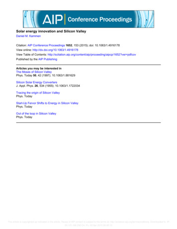
.the world's most energy friendly microcontrollers1 Analog Comparator1.1 IntroductionThe Analog Comparator is used to compare the voltage of two analog inputs, with a digital outputindicating which input voltage is higher. Inputs can either be one of the selectable internal references orfrom external pins. The comparator output can be sent directly to GPIO or PRS. A capacitive sense modeis also available, this enables the comparator to be used for capacitive touch applications. Responsetime and thereby also the current consumption can be configured by altering the current supply to thecomparator. The internal references can operate both in normal and low power mode.1.2 OverviewThe next image illustrates the internal connections of the inputs, the reference selection and outputmodes.Figure 1.1. Analog Comparator Internal ConnectionsPOSSELACMPn CH0ACMPn CH1ACMPn CH2ACMPn CH3ACMPn CH4ACMPn CH5ACMPn CH6ACMPn CH7000111Warm up interruptWarm - upcounterENACMPACTEdge interrupt10ACMPOUTOutput to Output to GPIOGPIOINVRead/ Write registersRead only registersNEGSELVDDLEVELLPREFVSSVDD SCALEDScalerVDD2.5 V1.25 VThe comparator has two analog inputs, one positive and one negative. When the comparator is active,the output indicates which of the two input voltages is higher. When the voltage on the positive input ishigher than the negative input voltage, the digital output is high and vice versa.One of the eight input pins can be selected as both positive and negative input to the comparator. Theinternal references are selectable only as negative inputs.The output of the comparator can be read in the ACMPOUT bit in ACMPn STATUS. It is possible toswitch inputs while the comparator is enabled, but all other configuration should only be changed whilethe comparator is disabled.2013-09-16 - an0020 Rev1.082www.silabs.com
.the world's most energy friendly microcontrollers2 Configuration2.1 Input SelectionThe POSSEL and NEGSEL fields in ACMPn INPUTSEL controls which signals are connected to thetwo inputs of the comparator. 8 external pins are available for both the negative and positive input.For the negative input, 3 additional internal reference sources are available; 1.25 V bandgap, 2.5Vbandgap and VDD. The VDD reference is scalable by a configurable factor, which is set in VDDLEVEL(in ACMPn INPUTSEL) according to the following formula:VDD ScaledVDD SCALED VDD VDDLEVEL/63(2.1)2.2 Warm-UpWhen the EN bit in ACMPn CTRL is set, the comparator must stabilize before becoming active and theoutputs can be used. This time period is called the warm-up time.The warm-up time is a configurable number of peripheral clock (HFPERCLK) cycles, set in WARMTIME,which should be set to at least 10 µs. When the comparator is enabled and warmed up, the ACMPACTbit in ACMPn STATUS will indicate that the comparator is active. The output value when the comparatoris inactive is set to the value in INACTVAL in ACMPn CTRL.If HFPERCLK is 14 MHz, 140 cycles equals a delay of 10us, the closest available selection above thisis 256 cycles.2.3 Interrupts and PRSThe analog comparator includes an edge triggered interrupt flag (EDGE in ACMPn IF). If either IRISEand/or IFALL in ACMPn CTRL is set, the EDGE interrupt flag will be set on rising and/or falling edgeof the comparator output respectively. An interrupt request will be sent if the EDGE interrupt flag inACMPn IF is set and interrupt is enabled through the EDGE bit in ACMPn IEN. The edge interrupt canalso be used to wake up the device from EM3-EM1.The analog comparator also includes a warm-up complete interrupt flag, WARMUP in ACMPn IF, whichis set when the warm-up sequence has finished. An interrupt request will be sent if the WARMUP interruptflag in ACMPn IF is set and the warm-up interrupt is enabled through the WARMUP bit in ACMPn IEN.The synchronized comparator outputs are also available as a PRS output signals. This can be configuredwith the PRS SourceSignalSet function in efm32 prs.c.2.4 Output to GPIOThe output from the comparator and the capacitive sense are available as alternate functions to the GPIOpins. Set the ACMPPEN bit in ACMPn ROUTE to enable output to pin. The LOCATION bits selects theoutput pin location. Even though the GPIO pin is automatically configured as output when the ACMPPENbit is set, the drive level and other GPIO features are not changed, and should be configured prior tosetting the ACMPPEN bit. The pin output can be inverted by setting the GPIOINV bit in ACMPn CTRL.For example, if setting the ACMPPEN bit in ACMP0 ROUTE and enabling an alternate location bysetting the LOCATION bits to 1, the output will be enabled and routed to PE2.2.5 Software ExampleThe acmp conf example configures ACMP0 with channel 4 (PC4) as positive input and the 1.25 Vbandgap reference as negative input. The warm-up time is configured for 14 MHz. Output to GPIO is2013-09-16 - an0020 Rev1.083www.silabs.com
.the world's most energy friendly microcontrollersalso activated and routed to the alternative location, which is PE2 for ACMP0 on the Gecko and GiantGecko Starter Kit and PD6 on the Tiny Gecko Starter Kit. The EFM32 wakes up every 100 ms andupdates the LCD with the current comparator output value.Use a small lead to short the comparator input to either GND or VDD and see the result on the LCD.The acmp int example uses the ACMP0 edge interrupt to wake up the EFM32 from EM2. Input isapplied to channel 4 (PC4) and the 2.5 V bandgap reference is used as the negative input. The LCDis only updated every time the compare output is updated. The analog comparator can also wake theEFM32 up from EM3, but this example uses the LCD, which is not active in EM3.2013-09-16 - an0020 Rev1.084www.silabs.com
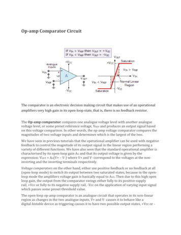
.the world's most energy friendly microcontrollers3 Additional Features3.1 HysteresisIn the analog comparator, hysteresis can be turned off or configured to 7 different levels, this is donethrough the HYSTSEL field in ACMPn CTRL. When the hysteresis level is set above 0, the digital outputwill not toggle until the positive input voltage is at a voltage equal to the hysteresis level above or belowthe negative input voltage. This feature can be used to filter out uninteresting input fluctuations aroundzero and only show changes that are big enough to breach the hysteresis threshold.Figure 3.1. 20 mV Hysteresis SelectedIn POSIn NEG 20m VIn NEGIn NEG - 20m VTim eACMPOUT without hysteresisACMPOUT with hysteresis3.2 Response TimeThere is a delay from when the actual input voltage changes polarity, until the output toggles. Thisperiod is called the response time and can be altered by increasing or decreasing the bias current to thecomparator through the BIASPROG, FULLBIAS and HALFBIAS fields in the ACMPn CTRL register.Setting the HALFBIAS bit in ACMPn CTRL effectively halves the current, while setting the FULLBIASbit multiplies the current by 65. Setting a lower bias current will result in lower power consumption, buta longer response time. For a table with actual current values, the reader is referred to the referencemanual.If the FULLBIAS bit is set, the highest hysteresis level should be used to avoid glitches on the output.3.3 Low Power ReferenceA low power reference mode can be enabled by setting the LPREF bit in ACMPn INPUTSEL. In thismode, the power consumption in the reference buffer (VDD and bandgap) is lowered at the cost ofaccuracy. Low power mode will only save power if VDD with VDDLEVEL higher than 0 or a bandgapreference is selected. During warm-up of the analog comparator the LPREF bit should be 0.2013-09-16 - an0020 Rev1.085www.silabs.com
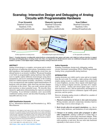
.the world's most energy friendly microcontrollers4 Window Mode4.1 Window Mode with two Analog ComparatorsOften it is necessary to know if a voltage is between, above or below two predefined thresholds. Thisis possible using two analog comparators (see Figure 4.1 (p. 6) ). The input signal is sent to thepositive input of both comparators, compared against the lower threshold using one comparator, andcompared against the upper threshold using the other comparator. If both comparators outputs 0, thesignal is below the lower threshold, if the lower threshold comparator outputs 1 and the upper thresholdcomparator outputs 0, the input is within the selected range. Finally if both comparators outputs 1, theinput is above the predefined range (see Figure 4.2 (p. 7) ).Since the input signal needs to be available to both comparators at the same time, one need to connectthe positive input pins for the two comparators together.Figure 4.1. Two Analog Comparators in Window ModeACMP0,1 POSACMP1 NEGACMP0 NEG2013-09-16 - an0020 Rev1.086www.silabs.com
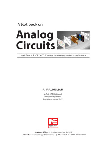
.the world's most energy friendly microcontrollersFigure 4.2. Example Wave Form, Window ModeInputACMP1 NEGACMP0,1 POSWindowACMP0 NEGTim eACMP1 OutACMP0 OutInside window4.2 Software ExampleThe acmp window example is available on the Gecko and Tiny Gecko Starter Kit. It configures analogcomparator 0 as lower boundary with the VDD scaled to 1 V as negative input. Analog comparator 1 isconfigured as upper boundary with VDD scaled to 2 V as its negative input. The scaling of the upperand lower boundary assumes that VDD is 3.3 V.The positive input is channel 4 for both comparators, this corresponds to PC4 and PC12 for ACMP0 andACMP1 respectively. These pins should be connected together externally using a jumper cable. Thisis easy on both the DVK and STK because these pins are located on the protoboard for the DVK andthe expansion header of the STK.2013-09-16 - an0020 Rev1.087www.silabs.com
.the world's most energy friendly microcontrollers5 Revision History5.1 Revision 1.082013-09-03New cover layout5.2 Revision 1.072013-05-08Added software projects for ARM-GCC and Atollic TrueStudio.5.3 Revision 1.062012-11-12Adapted software projects to new kit-driver and bsp structure.Added projects for Tiny and Giant Gecko STKs.5.4 Revision 1.052012-04-20Adapted software projects to new peripheral library naming and CMSIS V3.5.5 Revision 1.042011-11-17Updated IDE project paths with new kits directory.5.6 Revision 1.032011-07-14Changed window mode example to use scaled VDD.Changed interrupt driven example to use 1V25 bandgap.Updated projects to align with new bsp version.5.7 Revision 1.022011-05-18Updated projects to align with new bsp version.5.8 Revision 1.012010-11-16Removed lcdcontroller.c from IDE-project files.Changed example folder structure, removed build and src folders.2013-09-16 - an0020 Rev1.088www.silabs.com
.the world's most energy friendly microcontrollersUpdated chip init function to newest efm32lib version.5.9 Revision 1.002010-09-27Initial revision.2013-09-16 - an0020 Rev1.089www.silabs.com
.the world's most energy friendly microcontrollersA Disclaimer and TrademarksA.1 DisclaimerSilicon Laboratories intends to provide customers with the latest, accurate, and in-depth documentationof all peripherals and modules available for system and software implementers using or intending to usethe Silicon Laboratories products. Characterization data, available modules and peripherals, memorysizes and memory addresses refer to each specific device, and "Typical" parameters provided can anddo vary in different applications. Application examples described herein are for illustrative purposesonly. Silicon Laboratories reserves the right to make changes without further notice and limitation toproduct information, specifications, and descriptions herein, and does not give warranties as to theaccuracy or completeness of the included information. Silicon Laboratories shall have no liability forthe consequences of use of the information supplied herein. This document does not imply or expresscopyright licenses granted hereunder to design or fabricate any integrated circuits. The products mustnot be used within any Life Support System without the specific written consent of Silicon Laboratories.A "Life Support System" is any product or system intended to support or sustain life and/or health, which,if it fails, can be reasonably expected to result in significant personal injury or death. Silicon Laboratoriesproducts are generally not intended for military applications. Silicon Laboratories products shall under nocircumstances be used in weapons of mass destruction including (but not limited to) nuclear, biologicalor chemical weapons, or missiles capable of delivering such weapons.A.2 Trademark InformationSilicon Laboratories Inc., Silicon Laboratories, the Silicon Labs logo, Energy Micro, EFM, EFM32, EFR,logo and combinations thereof, and others are the registered trademarks or trademarks of SiliconLaboratories Inc. ARM, CORTEX, Cortex-M3 and THUMB are trademarks or registered trademarksof ARM Holdings. Keil is a registered trademark of ARM Limited. All other products or brand namesmentioned herein are trademarks of their respective holders.2013-09-16 - an0020 Rev1.0810www.silabs.com
.the world's most energy friendly microcontrollersB Contact InformationSilicon Laboratories Inc.400 West Cesar ChavezAustin, TX 78701Please visit the Silicon Labs Technical Support web chnicalsupport.aspxand register to submit a technical support request.2013-09-16 - an0020 Rev1.0811www.silabs.com
.the world's most energy friendly microcontrollersTable of Contents1. Analog Comparator . 21.1. Introduction . 21.2. Overview . 22. Configuration . 32.1. Input Selection . 32.2. Warm-Up . 32.3. Interrupts and PRS . 32.4. Output to GPIO . 32.5. Software Example . 33. Additional Features . 53.1. Hysteresis . 53.2. Response Time . 53.3. Low Power Reference . 54. Window Mode . 64.1. Window Mode with two Analog Comparators . 64.2. Software Example . 75. Revision History . 85.1. Revision 1.08 . 85.2. Revision 1.07 . 85.3. Revision 1.06 . 85.4. Revision 1.05 . 85.5. Revision 1.04 . 85.6. Revision 1.03 . 85.7. Revision 1.02 . 85.8. Revision 1.01 . 85.9. Revision 1.00 . 9A. Disclaimer and Trademarks . 10A.1. Disclaimer . 10A.2. Trademark Information . 10B. Contact Information . 11B.1. . 112013-09-16 - an0020 Rev1.0812www.silabs.com
.the world's most energy friendly microcontrollersList of Figures1.1.3.1.4.1.4.2.Analog Comparator Internal Connections .20 mV Hysteresis Selected .Two Analog Comparators in Window Mode .Example Wave Form, Window Mode .2013-09-16 - an0020 Rev1.0813www.silabs.com2567
.the world's most energy friendly microcontrollersList of Equations2.1. VDD Scaled . 32013-09-16 - an0020 Rev1.0814www.silabs.com
The acmp_window example is available on the Gecko and Tiny Gecko Starter Kit. It configures analog comparator 0 as lower boundary with the VDD scaled to 1 V as negative input. Analog comparator 1 is configured as upper boundary with VDD scaled to 2 V as its negative input. The scaling of the upper and lower boundary assumes that VDD is 3.3 V.