Transcription
sWelcome to STEP 7,ContentsSIMATICWorking with STEP 7Getting StartedIntroduction to STEP 71The SIMATIC Manager2Programming with Symbols3Creating a Program in OB14Creating a Program withFunction Blocks and Data Blocks5Configuring the Central Rack6Downloading and Debuggingthe Program7Programming a Function8Programming aShared Data Block9Programming a Multiple Instance10Configuring the Distributed I/O11AppendixAppendix AIndexThis manual is part of the documentationpackage with the order number:6ES7810-4CA08-8BW0Edition 03/2006C79000-P7076-C48-01A
Safety GuidelinesThis manual contains notices you have to observe in order to ensure your personal safety, as well as toprevent damage to property. The notices referring to your personal safety are highlighted in the manualby a safety alert symbol, notices referring to property damage only have no safety alert symbol. Thenotices shown below are graded according to the degree of danger.Danger!indicates that death or severe personal injury will result if proper precautions are not taken.!indicates that death or severe personal injury may result if proper precautions are not taken.!WarningCautionwith a safety alert symbol indicates that minor personal injury can result if proper precautions are nottaken.Cautionwithout a safety alert symbol indicates that property damage can result if proper precautions are nottaken.Noticeindicates that an unintended result or situation can occur if the corresponding notice is not taken intoaccount.If more than one degree of danger is present, the warning notice representing the highest degree ofdanger will be used. A notice warning of injury to persons with a safety alert symbol may also include awarning relating to property damage.Qualified PersonnelThe device/system may only be set up and used in conjunction with this documentation. Commissioningand operation of a device/system may only be performed by qualified personnel. Within the context ofthe safety notices in this documentation qualified persons are defined as persons who are authorized tocommission, ground and label devices, systems and circuits in accordance with established safetypractices and standards.Prescribed UsageNote the following:!WarningThis device and its components may only be used for the applications described in the catalog or thetechnical description, and only in connection with devices or components from other manufacturerswhich have been approved or recommended by Siemens.Correct, reliable operation of the product requires proper transport, storage, positioning and assemblyas well as careful operation and maintenance.TrademarksAll names identified by are registered trademarks of the Siemens AG.The remaining trademarks in this publication may be trademarks whose use by third parties for theirown purposes could violate the rights of the owner.Disclaimer of LiabilityWe have reviewed the contents of this publication to ensure consistency with the hardware andsoftware described. Since variance cannot be precluded entirely, we cannot guarantee full consistency.However, the information in this publication is reviewed regularly and any necessary corrections areincluded in subsequent editions.Siemens AGAutomation and DrivesPostfach 484890437 t Siemens AG 2006Technical data subject to change
Welcome to STEP 7.the SIMATIC standard software for creating programmable logic controlprograms in Ladder Logic, Function Block Diagram, or Statement List forSIMATIC S7-300/400 stations.About This Getting Started ManualIn this manual, you will get to know the basics of SIMATIC STEP 7. We will showyou the most important screen dialog boxes and the procedures to follow usingpractical exercises, which are structured so that you can start with almost anychapter.Each section is split into two parts: a descriptive part, marked in gray, and aprocess-oriented part, marked in green. The instructions start with an arrow in thegreen margin and may be spread out over several pages, finishing in a full stopand a box containing related topics.Previous experience of working with the mouse, window handling, pull-downmenus, etc. would be useful, and you should preferably be familiar with the basicprinciples of programmable logic control.The STEP 7 training courses provide you with in-depth knowledge above andbeyond the contents of this Getting Started manual, teaching you how entireautomation solutions can be created with STEP 7.Requirements for Working with the Getting Started ManualIn order to carry out the practical exercises for STEP 7 in this Getting Startedmanual, you require the following: A Siemens programming device or a PC The STEP 7 software package and the respective license key A SIMATIC S7-300 or S7-400 programmable controller(for Chapter 7 "Downloading and Debugging the Program").Additional Documentation on STEP 7 STEP 7 Basic Information STEP 7 Reference InformationAfter you have installed STEP 7, you will find the electronic manuals in the Startmenu under Simatic Documentation or alternatively, you can order them fromany Siemens sales center. All of the information in the manuals can be called up inSTEP 7 from the online help.Have fun and good luck!SIEMENS AGSTEP 7 Getting StartedC79000-P7076-C48-01iii
Welcome to STEP 7.ivSTEP 7 Getting StartedC79000-P7076-C48-01
Contents1Introduction to STEP 71.1What You Will Learn1-11.2Combining Hardware and Software1-31.3Basic Procedure Using STEP 71-41.4Installing STEP 71-52The SIMATIC Manager2.1Starting the SIMATIC Manager and Creating a Project2-12.2The Project Structure in the SIMATIC Managerand How to Call the Online Help2-4In Chapters 3 to 5, you create asimple program.3Programming with Symbols3.1Absolute Addresses3-13.2Symbolic Programming3-24Creating a Program in OB14.1Opening the LAD/STL/FBD Program Window4-14.2Programming OB1 in Ladder Logic4-44.3Programming OB1 in Statement List4-84.4Programming OB1 in Function Block Diagram4-115Creating a Program with Function Blocks and Data Blocks5.1Creating and Opening Function Blocks (FB)5-15.2Programming FB1 in Ladder Logic5-35.3Programming FB1 in Statement List5-75.4Programming FB1 in Function Block Diagram5-105.5Generating Instance Data Blocks and Changing Actual Values5-145.6Programming a Block Call in Ladder Logic5-165.7Programming a Block Call in Statement List5-195.8Programming a Block Call in Function Block Diagram5-21STEP 7 Getting StartedC79000-P7076-C48-01v
ContentsIn Chapters 6 and 7, youconfigure the hardware and testyour program.6Configuring the Central Rack6.1Configuring Hardware7Downloading and Debugging the Program7.1Establishing an Online Connection7-17.2Downloading the Program to the Programmable Controller7-37.3Testing the Program with Program Status7-67.4Testing the Program with the Variable Table7-87.5Evaluating the Diagnostic Buffer7-126-1In Chapters 8 to 11, you canextend your knowledge to includenew functions.8Programming a Function8.1Creating and Opening Functions (FC)8-18.2Programming Functions8-38.3Calling the Function in OB18-69Programming a Shared Data Block9.1Creating and Opening Shared Data Blocks10Programming a Multiple Instance9-110.1 Creating and Opening a Higher-Level Function Block10-110.2 Programming FB1010-310.3 Generating DB10 and Adapting the Actual Value10-710.4 Calling FB10 in OB110-911Configuring the Distributed I/O11.1 Configuring the Distributed I/O with PROFIBUS DP11-1Appendix AA-1Overview of the Sample Projects for the Getting Started ManualIndexviIndex-1STEP 7 Getting StartedC79000-P7076-C48-01
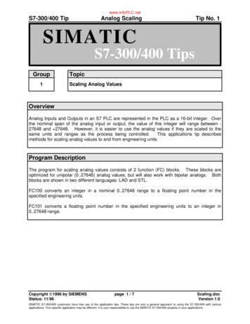
1Introduction to STEP 71.1What You Will LearnUsing practical exercises, we will show you how easy it is to program in LadderLogic, Statement List, or Function Block Diagram with STEP 7.Detailed instructions in the individual chapters will show you step-by-step themany ways in which you can use STEP 7.Creating a Program with Binary LogicIn Chapters 2 to 7, you will create a program with binary logic. Using theprogrammed logic operations, you will address the inputs and outputs of your CPU(if present).The programming examples in the Getting Started manual are based, among otherthings, on three fundamental binary logic operations.The first binary logic operation, which you will program later on, is the ANDfunction. The AND function can be best illustrated in a circuit diagram using twokeys.Key 1Key 2If both Key 1 and Key 2are pressed, the bulblights up.The second binary logic operation is the OR function. The OR function can also berepresented in a circuit diagram.Key 3Key 4STEP 7 Getting StartedC79000-P7076-C48-01If either key 3 or key 4is pressed, the bulblights up.1-1
Introduction to STEP 7The third binary logic operation is the memory element. The SR function reactswithin a circuit diagram to certain voltage states and passes these on accordingly.Memory ElementKey SSRKey RIf key S is pressed, the bulb lights upand remains lit until key R is pressed.1-2STEP 7 Getting StartedC79000-P7076-C48-01
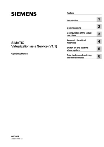
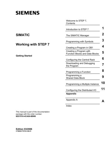
Introduction to STEP 71.2Combining Hardware and SoftwareUsing the STEP 7 software, you can create your S7 program within a project. TheS7 programmable controller consists of a power supply unit, a CPU, and input andoutput modules (I/O modules).The programmable logic controller (PLC) monitors and controls your machine withthe S7 program. The I/O modules are addressed in the S7 program via theaddresses.Programmingdevice cableProgramming deviceTransferring a programSTEP 7 softwareMachine to becontrolledCPUPower supply moduleSTEP 7 Getting StartedC79000-P7076-C48-01Output moduleInput module1-3
Introduction to STEP 71.3Basic Procedure Using STEP 7Before you create a project, you should know that STEP 7 projects can be createdin different orders.Designing the solution to the automation taskCreating a project (Chapter 2)Option 1Option 2Configuring the hardware(Chapter 6)Creating a program(Chapters 3 to 5)Creating a program(Chapters 3 to 5)Configuring the hardware(Chapter 6)Transferring the program to the CPU and debugging(Chapter 7)If you are creating comprehensive programs with many inputs and outputs, werecommend you configure the hardware first. The advantage of this is that STEP 7displays the possible addresses in the Hardware Configuration Editor.If you choose the second option, you have to determine each address yourself, dependingon your selected components and you cannot call these addresses via STEP 7.In the hardware configuration, not only can you define addresses, but you can also changethe parameters and properties of modules. If you want to operate several CPUs, forexample, you have to match up the MPI addresses of the CPUs.Since we are only using a small number of inputs andoutputs in the Getting Started manual, we will skip thehardware configuration for now and start with theprogramming.1-4STEP 7 Getting StartedC79000-P7076-C48-01
Introduction to STEP 71.4Installing STEP 7Regardless of whether you want to start with programming or configuringhardware, you first have to install STEP 7. If you are using a SIMATICprogramming device, STEP 7 is already installed.When installing the STEP 7 softwareon a programming device or PCwithout a previously installed version ofSTEP 7, note the software andhardware requirements. You can findthese in the Readme.wri on theSTEP 7 CD under Drive :\STEP 7 \Disk1.If you need to install STEP 7 first,insert the STEP 7 CD in the CD-ROMdrive now. The installation programstarts automatically. Follow theinstructions on the screen.If the installation does not start automatically, you can also find theinstallation program on the CD-ROMunder Drive :\STEP 7 \Disk1\setup.exe.Once the installation is complete andyou have restarted the computer, the"SIMATIC Manager" icon will appearon your Windows desktop.If you double-click the "SIMATIC Manager" icon following installation, the STEP 7 Wizardwill be started automatically.You can find additional notes on installation in theReadme.wri file on the STEP 7 CD under Drive :\STEP 7 \Disk1\Readme.wri.STEP 7 Getting StartedC79000-P7076-C48-011-5
Introduction to STEP 71-6STEP 7 Getting StartedC79000-P7076-C48-01
22.1The SIMATIC ManagerStarting the SIMATIC Manager and Creating a ProjectThe SIMATIC Manager is the central window which becomes active when STEP 7is started. The default setting starts the STEP 7 Wizard, which supports you whencreating a STEP 7 project. The project structure is used to store and arrange allthe data and programs in order.Within the project, data are stored in theform of objects in a hierarchical structureThe SIMATIC station and the CPUcontain the configuration andparameter data of the hardwareThe S7 program comprises all theblocks with the programs necessary forcontrolling the machineDouble-click the SIMATIC Managericon on the Windows desktop, thenselect the File Wizard "NewProject" menu command if the wizarddoes not start automatically.In the preview, you can toggle the viewof the project structure being createdon and off.To move to the next dialog box, clickNext.STEP 7 Getting StartedC79000-P7076-C48-012-1
The SIMATIC ManagerFor the "Getting Started" sampleproject, select CPU 314. The examplehas been created in such a way thatyou can actually select the CPU youhave been supplied with at any time.The default setting for the MPI addressis 2.Click Next to confirm the settings andmove to the next dialog box.Every CPU has certainproperties; for example,regarding its memoryconfiguration or addressareas. This is why you haveto select the CPU before youstart programming.The MPI address (multipointinterface) is required in orderfor your CPU to communicatewith your programming deviceor PC.Select the organization block OB1 (ifthis is not already selected).Select one of the programminglanguages: Ladder Logic (LAD),Statement List (STL), or Function BlockDiagram (FBD).Confirm your settings with Next.OB1 represents the highestprogramming level and organizes theother blocks in the S7 program.You can change the programminglanguage again at a later date.2-2STEP 7 Getting StartedC79000-P7076-C48-01
The SIMATIC ManagerDouble-click to select the suggestedname in the "Project name" field andoverwrite it with "Getting Started."Click Make to generate your newproject according to the preview.When you click the Make button, the SIMATIC Manager will open with the window for the"Getting Started" project you have created. On the following pages, we will show you whatthe created files and folders are for and how you can work effectively with them.The STEP 7 Wizard is activated each time the program is started. You can deactivate thisdefault setting in the first dialog box for the Wizard. However, if you create projects withoutthe STEP 7 Wizard, you must create each directory within the project yourself.You can find more information underHelp Contents in the topic "SettingUp and Editing the Project."STEP 7 Getting StartedC79000-P7076-C48-012-3
The SIMATIC Manager2.2The Project Structure in the SIMATIC Manager and Howto Call the Online HelpAs soon as the STEP 7 Wizard is closed, the SIMATIC Manager appears with theopen project window "Getting Started." From here, you can start all the STEP 7functions and windows.Opening, organizing, and printingprojectsEditing blocks and inserting programcomponentsSetting the window display andarrangement, selecting thelanguage, and making settings forprocess dataDownloading the programand monitoring thehardwareCalling the STEP 7 online helpThe contents of the right-hand paneshow the objects and other foldersfor the folder selected on the leftThe contents of the left-hand paneshow the project structure2-4STEP 7 Getting StartedC79000-P7076-C48-01
The SIMATIC ManagerCalling the Help on STEP 7F1Option 1:Place the cursor on any menucommand and press the F1 key. Thecontext-sensitive help for the selectedmenu command will appear.Option 2:Use the menu to open the STEP 7online help.The contents page with various helptopics appears in the left-hand paneand the selected topic is displayed inthe right-hand pane.Navigate to the topic you want byclicking the sign in the Contents list.At the same time, the contents of theselected topic are displayed in theright-hand pane.Using Index and Find, you can entersearch strings and look for the specifictopics you require.Option 3:Click on the "Start page" icon in theSTEP 7 Online Help to open theinformation portal. This portal providescompact access to major topics of theOnline Help, e.g.: Getting Started with STEP 7Configuring & ProgrammingTesting & DebuggingSIMATIC on the InternetOption 4:Click on the question mark button inthe toolbar to turn your mouse into ahelp cursor. The next time you click ona specific object, the online help isactivated.STEP 7 Getting StartedC79000-P7076-C48-012-5
The SIMATIC ManagerNavigating in the Project StructureThe project you have just created isdisplayed with the selected S7 stationand CPU.Click the or – sign to open or close afolder.You can start other functions later onby clicking the symbols displayed inthe right-hand pane.Click the S7 Program (1) folder. Thiscontains all the necessary programcomponents.You will use the Symbols component inChapter 3 to give the addressessymbolic names.The Source Files component is used tostore source file programs. These arenot dealt with in the Getting Startedmanual.Click the Blocks folder. This containsthe OB1 you have already createdand, later on, all the other blocks.From here, you will start programmingin Ladder Logic, Statement List, orFunction Block Diagram in Chapters 4and 5.Click the SIMATIC 300 Station folder.All the hardware-related project dataare stored here.You will use the Hardware componentin Chapter 6 to specify the parametersof your programmable controller.If you require further SIMATIC software for your automation task; for example, the optionalpackages PLCSIM (hardware simulation program) or S7 Graph (graphic programminglanguage), these are also integrated in STEP 7. Using the SIMATIC Manager, for example,you can directly open the relevant objects such as an S7 Graph function block.You can find more information under Help Contents in the topics "WorkingOut the Automation Concept" and "Basics of Designing the Program Structure".You can find more information on optional packages in the SIMATIC catalogST 70, "Components for Completely Integrated Automation."2-6STEP 7 Getting StartedC79000-P7076-C48-01
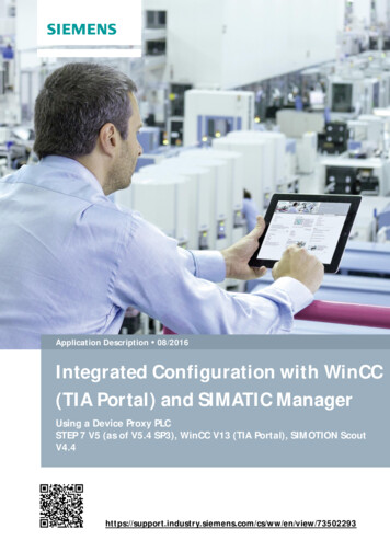
3Programming with Symbols3.1Absolute AddressesEvery input and output has an absolute address predefined by the hardwareconfiguration. This address is specified directly; that is, absolutely.The absolute address can be replaced by any symbolic name you choose.Digital inputmoduleByte 0Bits 0 to 7011DC 5V22FRCE33RUN44STOP556667770011223344556677RUN PRUNONOFFSTOPM RESL NL ML MDigital inputmoduleByte 1Bits 0 to 7ML MAbsolute address:InputDigital outputmoduleByte 4Bits 0 to 70BATFSFIByte 10123450Digital outputmoduleByte 5Bits 0 to 712345671.5Bit 5You should only use absolute programming if you do nothave to address many inputs and outputs in your S7program.STEP 7 Getting StartedC79000-P7076-C48-013-1
Programming with Symbols3.2Symbolic ProgrammingIn the symbol table, you assign a symbolic name and the data type to all theabsolute addresses which you will address later on in your program; for example,for input I 0.1 the symbolic name Key 1. These names apply to all parts of theprogram and are known as global variables.Using symbolic programming, you can considerably improve the legibility of theS7 program you have created.Working with the Symbol EditorNavigate in the project window "GettingStarted" until you reachS7 Program (1) and double-click toopen the Symbols component.Your symbol table currently onlyconsists of the predefined organizationblock OB1.Click Cycle Execution and overwrite itwith "Main Program" for our example.Enter "Green Light" and "Q 4.0" inrow 2. The data type is addedautomatically.Click in the comment column of row 1or 2 to enter a comment on the symbol.You complete your entries in a row bypressing Enter, which then adds a newrow.Enter "Red Light" and "Q 4.1" in row 3and press Enter to complete the entry.In this way, you can assign symbolic names to allthe absolute addresses of the inputs and outputswhich your program requires.3-2STEP 7 Getting StartedC79000-P7076-C48-01
Programming with SymbolsSave the entries or changes you havemade in the symbol table and close thewindow.Because there are lots of names for the entire "Getting Started" project, you cancopy the symbol table to your "Getting Started" project in Section 4.1.Here you can see the symboltable for the S7 program in the"Getting Started" example forStatement List.Generally speaking, only onesymbol table is created perS7 program, regardless ofwhich programming languageyou have selected.All printable characters (forexample, special characters,spaces) are permitted in thesymbol table.The data type which was previously added automatically to the symbol table determines thetype of the signal to be processed for the CPU. STEP 7 uses, among others, the followingdata TETIME OF DAYSTEP 7 Getting StartedC79000-P7076-C48-01Data of this type are bit combinations. 1 bit (type BOOL) to 32 bits (DWORD).Data of this type occupy exactly one character of the ASCII character set.They are available for the processing of numerical values (for example, to calculatearithmetic expressions).Data of this type represent the different time and date values within STEP 7 (forexample, to set the date or to enter the time value for a timer).You can find more information under Help Contents in the topics “Programming Blocks“and "Defining Symbols".3-3
Programming with Symbols3-4STEP 7 Getting StartedC79000-P7076-C48-01
4Creating a Program in OB14.1Opening the LAD/STL/FBD Program WindowChoosing Ladder Logic, Statement List, or Function Block DiagramWith STEP 7, you create S7 programs in the standard languages Ladder Logic(LAD), Statement List (STL), or Function Block Diagram (FBD). In practice, and forthis chapter too, you must decide which language to use.Ladder Logic (LAD)Suitable for users from the electrical engineering industry, for example.Statement List (STL)Suitable for users from the world of computer technology, for example.Function Block Diagram (FBD)Suitable for users from the world of circuit engineering, for example.The block OB1 will now be opened according to the language you chosewhen you created it in the project Wizard. However, you can change thedefault programming language again at any time.STEP 7 Getting StartedC79000-P7076-C48-014-1
Creating a Program in OB1Copying the Symbol Table and Opening OB1If necessary, open your "GettingStarted" project. To do this, click theOpen button in the toolbar, select the"Getting Started" project you created,and confirm with OK.Depending on which programminglanguage you have decided to use, inthe "Sample projects" tab open one ofthe following projects as well: ZEn01 05 STEP7 LAD 1-9 ZEn01 01 STEP7 STL 1-9or ZEn01 03 STEP7 FDB 1-9Here you can see all three sampleprojects displayed.Navigate in the "ZEn01 XXX“ until youreach the Symbols component andcopy this by dragging and dropping itto the S7 Program folder in yourproject window "Getting Started."Then close the window "ZEn01 XXX“.Drag and drop means that you click any objectwith the mouse and move it whilst keeping themouse button depressed. When you release themouse button, the object is pasted at the selectedposition.Double-click OB1 in the "GettingStarted" project. The LAD/STL/FBDprogram window is opened.In STEP 7, OB1 is processed cyclically by the CPU. The CPU reads line by line andexecutes the program commands. When the CPU returns to the first program line, it hascompleted exactly one cycle. The time required for this is known as the scan cycle time.Depending on which programming language you have selected, continue reading in eitherSection 4.2 for programming in Ladder Logic, Section 4.3 for Statement List, or Section 4.4for Function Block Diagram.You can find more information under Help Contentsin the topics “Programming Blocks“ and "CreatingBlocks and Libraries.“4-2STEP 7 Getting StartedC79000-P7076-C48-01
Creating a Program in OB1The LAD/STL/FBD Program WindowAll blocks are programmed in the LAD/STL/FBD program window. Here, you cansee the view for Ladder Logic.Inserting a newnetworkToggling "Program elements" and "Callstructure" on and offThe most important programelements for Ladder Logic andFunction Block Diagram(Pane can be placed anywhere in theprogram window)Changing the programminglanguage viewProgramelements(here forLadder Logic)and callstructureThe variable declaration table containsthe parameters and local variables forthe blockTitle and comment field forthe block or networkProgram input line (also networkand current path)Information on the selected program elementSTEP 7 Getting StartedC79000-P7076-C48-01The different tabs of the "Details" windoware for displaying error messages andinformation on addresses, for editingsymbols, monitoring addresses,comparing blocks and for editing errordefinitions for the process diagnostics.4-3
Creating a Program in OB14.2Programming OB1 in Ladder LogicIn the following section, you will program a series circuit, a parallel circuit, and theset / reset memory function in Ladder Logic (LAD).Programming a Series Circuit in Ladder LogicIf necessary, set LAD as theprogramming language in the Viewmenu.Click in the title area of OB1 and enter"Cyclically processed main program,"for example.Select the current path for your firstelement.Click the button in the toolbar andinsert a normally open contact.In the same way, insert a secondnormally open contact.Insert a coil at the right-hand end of thecurrent path.The addresses of the normally opencontacts and the coil are still missing inthe series circuit.Check whether symbolicrepresentation is activated.4-4STEP 7 Getting StartedC79000-P7076-C48-01
Creating a Program in OB1Click the ?.? sign and enter thesymbolic name "Key 1" (in quotationmarks). Alternatively, you can selectthe name from the displayed pull-downlist.Confirm with Enter.Enter the symbolic name "Key 2" forthe second normally open contact.Enter the name "Green Light" for thecoil.You have now programmed acomplete series circuit.Save the block if there are no moresymbols shown in red.Symbols are indicated in red if, for example, they do not exist in the symbol table, or ifthere is a syntax error.STEP 7 Getting StartedC79000-P7076-C48-014-5
Creating a Program in OB1Programming a Parallel Circuit in Ladder LogicSelect Network 1.Insert a new network.Select the current path again.Insert a normally open contact and acoil.Select the vertical line of the currentpath.Insert a parallel branch.Add another normally open contact inthe parallel branch.Close the branch (if necessary, selectthe lower arrow).The addresses are still missing in theparallel circuit.To assign symbolic addresses,proceed in the same way as for theseries circuit.Overwrite the upper normally opencontact with "Key 3," the lower contactwith "Key 4," and the coil with"Red Light."Save the block.4-6STEP 7 Getting StartedC79000-P7076-C48-01
Creating a Program in OB1Programming a Memory Function in Ladder LogicSelect Network 2 and insert anothernetwork.Select the current path again.Navigate in the Program Elementscatalog under Bit Logic until you reachthe SR element. Double-click to insertthe element.Insert a normally open contact in frontof each of the inputs S and R.Enter the following symbolic names forthe SR element:Upper contact "Automatic On"Lower contact "Manual On"SR element "Automatic Mode"Save the block and close the window.If you want to see the difference between absolute and symbolic addressing, deactivate themenu command View Display Symbolic Representation.Example:Symbolic addressing in LADExample:Absolute addressing in LADYou can change the line break for symbolic addressing in the LAD/STL/FBD programwindow by using the menu command Options Customize and then selecting "Width ofaddress field" in the "LAD/FBD" tab. Here you can set the line break between 10 and 26characters.You can find more information under Help Contents in the topics "Programming Blocks,""Creating Logic Blocks," and "Editing LadderInstructions."STEP 7 Getting StartedC79000-P7076-C48-014-7
Creating a Program in OB14.3Programming OB1 in Statement ListIn the following section, you will program an AND instruction, an OR instruction,and the memory instruction set/reset in Statement List (STL).Programming an AND Instruction in Statement ListIf necessary, set STL as theprogramming language in the Viewmenu.Check whether symbolicrepresentation is activated.Click in the title area of OB1 and enter"Cyclically processed main program,"for example.Select the area for your first statement.Type an A (AND) in the first programline, a space, and then the symbolicname "Key 1" (in quotation marks).Complete the line with Enter. Thecursor jumps to the next line.4-8STEP 7 Getting StartedC79000-P7076-C48-01
Creating a Program in OB1In the same way, complete the ANDinstruction as shown.You have now programmed acomplete AND instruction. Save theblock if there are no more symbolsshown in red.Symbols are indicated in red if, for example, they do not exist in the symbol table, orif there is a syntax error.Programming an OR Instruction in Statement ListSelect Network 1.Insert a new network and select theinput area again.Enter an O (OR) and the symbolicname "Key 3" (in the same way as forthe AND instruction).Complete the OR instruction and saveit.STEP 7 Getting StartedC79000-P7076-C48-014-9
Creating a Program in OB1Programming a Memory Instruction in Statement ListSelect Network 2 and insert anothernetwork.In the first line, type the instruction Awith the symbolic name"Automatic On."Co
S7 programmable controller consists of a power supply unit, a CPU, and input and output modules (I/O modules). The programmable logic controller (PLC) monitors and controls your machine with the S7 program. The I/O modules are addressed in the S7 program via the addresses. Input module CPU Output module Power supply module Transferring a program