Transcription
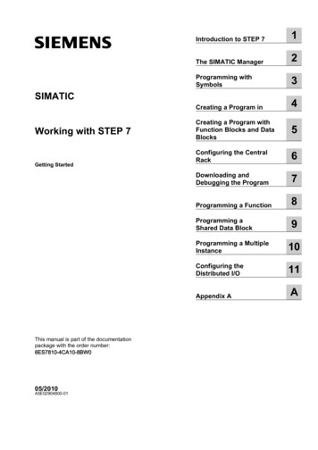
Introduction to STEP 71The SIMATIC Manager2Programming withSymbols3Creating a Program in4SIMATICWorking with STEP 7Getting StartedCreating a Program withFunction Blocks and DataBlocks5Configuring the CentralRack6Downloading andDebugging the Program7Programming a Function8Programming aShared Data Block9Programming a MultipleInstance10Configuring theDistributed I/O11Appendix AThis manual is part of the documentationpackage with the order number:6ES7810-4CA10-8BW005/2010A5E02904800-01A
Legal informationWarning notice systemThis manual contains notices you have to observe in order to ensure your personal safety, as well as to prevent damage toproperty. The notices referring to your personal safety are highlighted in the manual by a safety alert symbol, notices referringonly to property damage have no safety alert symbol. These notices shown below are graded according to the degree ofdanger.DANGERindicates that death or severe personal injury will result if proper precautions are not taken.WARNINGindicates that death or severe personal injury may result if proper precautions are not taken.CAUTIONwith a safety alert symbol, indicates that minor personal injury can result if proper precautions are not taken.CAUTIONwithout a safety alert symbol, indicates that property damage can result if proper precautions are not taken.NOTICEindicates that an unintended result or situation can occur if the corresponding information is not taken into account.If more than one degree of danger is present, the warning notice representing the highest degree of danger will be used. Anotice warning of injury to persons with a safety alert symbol may also include a warning relating to property damage.Qualified PersonnelThe product/system described in this documentation may be operated only by personnel qualified for the specific task inaccordance with the relevant documentation for the specific task, in particular its warning notices and safety instructions.Qualified personnel are those who, based on their training and experience, are capable of identifying risks and avoidingpotential hazards when working with these products/systems.Proper use of Siemens productsNote the following:WARNINGSiemens products may only be used for the applications described in the catalog and in the relevant technical documentation.If products and components from other manufacturers are used, these must be recommended or approved by Siemens.Proper transport, storage, installation, assembly, commissioning, operation and maintenance are required to ensure that theproducts operate safely and without any problems. The permissible ambient conditions must be adhered to. The information inthe relevant documentation must be observed.TrademarksAll names identified by are registered trademarks of the Siemens AG. The remaining trademarks in this publication may betrademarks whose use by third parties for their own purposes could violate the rights of the owner.Disclaimer of LiabilityWe have reviewed the contents of this publication to ensure consistency with the hardware and software described. Sincevariance cannot be precluded entirely, we cannot guarantee full consistency. However, the information in this publication isreviewed regularly and any necessary corrections are included in subsequent editions.Siemens AGIndustry SectorPostfach 48 4890026 NÜRNBERGGERMANYA5E02904800-01 02/2010Copyright Siemens AG 2010.Technical data subject to change
Welcome to STEP 7.the SIMATIC standard software for creating programmable logic control programs in LadderLogic, Function Block Diagram, or Statement List for SIMATIC S7-300/400 stations.About This Getting Started ManualIn this manual, you will get to know the basics of SIMATIC STEP 7. We will show you the mostimportant screen dialog boxes and the procedures to follow using practical exercises, which arestructured so that you can start with almost any chapter.Each section is split into two parts: a descriptive part, marked in gray, and a process-orientedpart, marked in green. The instructions start with an arrow in the green margin and may bespread out over several pages, finishing in a full stop and a box containing related topics.Previous experience of working with the mouse, window handling, pull-down menus, etc. wouldbe useful, and you should preferably be familiar with the basic principles of programmable logiccontrol.The STEP 7 training courses provide you with in-depth knowledge above and beyond thecontents of this Getting Started manual, teaching you how entire automation solutions can becreated with STEP 7.Requirements for Working with the Getting Started ManualIn order to carry out the practical exercises for STEP 7 in this Getting Started manual, yourequire the following: A Siemens programming device or a PC The STEP 7 software package and the respective license key A SIMATIC S7-300 or S7-400 programmable controller(for Chapter 7 "Downloading and Debugging the Program").Additional Documentation on STEP 7 STEP 7 Basic Information STEP 7 Reference InformationAfter you have installed STEP 7, you will find the electronic manuals in the Start menu underSimatic Documentation or alternatively, you can order them from any Siemens sales center.All of the information in the manuals can be called up in STEP 7 from the online help.Have fun and good luck!SIEMENS AGGetting Started STEP 7A5E02904800-013
Welcome to STEP 7.Getting Started STEP 74A5E02904800-01
Contents1Introduction to STEP 71.1What You Will Learn71.2Combining Hardware and Software91.3Basic Procedure Using STEP 7101.4Installing STEP 7112The SIMATIC Manager2.1Starting the SIMATIC Manager and Creating a Project132.2The Project Structure in the SIMATIC Managerand How to Call the Online Help16In Chapters 3 to 5, you create asimple program.3Programming with Symbols3.1Absolute Addresses193.2Symbolic Programming204Creating a Program in OB14.1Opening the LAD/STL/FBD Program Window234.2Programming OB1 in Ladder Logic264.3Programming OB1 in Statement List304.4Programming OB1 in Function Block Diagram335Creating a Program with Function Blocks and Data Blocks5.1Creating and Opening Function Blocks (FB)375.2Programming FB1 in Ladder Logic395.3Programming FB1 in Statement List435.4Programming FB1 in Function Block Diagram465.5Generating Instance Data Blocks and Changing Actual Values505.6Programming a Block Call in Ladder Logic525.7Programming a Block Call in Statement List555.8Programming a Block Call in Function Block Diagram57Getting Started STEP 7A5E02904800-015
ContentsIn Chapters 6 and 7, youconfigure the hardware and testyour program.6Configuring the Central Rack6.1Configuring Hardware7Downloading and Debugging the Program7.1Establishing an Online Connection637.2Downloading the Program to the Programmable Controller657.3Testing the Program with Program Status687.4Testing the Program with the Variable Table707.5Evaluating the Diagnostic Buffer7461In Chapters 8 to 11, you canextend your knowledge to includenew functions.8Programming a Function8.1Creating and Opening Functions (FC)778.2Programming Functions798.3Calling the Function in OB1829Programming a Shared Data Block9.1Creating and Opening Shared Data Blocks10Programming a Multiple Instance10.1Creating and Opening a Higher-Level Function Block8910.2Programming FB109110.3Generating DB10 and Adapting the Actual Value9510.4Calling FB10 in OB19711Configuring the Distributed I/O11.1Configuring the Distributed I/O with PROFIBUS DP85101109Appendix AOverview of the Sample Projects for the Getting Started ManualIndex111Getting Started STEP 76A5E02904800-01
1Introduction to STEP 71.1What You Will LearnUsing practical exercises, we will show you how easy it is to program in Ladder Logic, StatementList, or Function Block Diagram with STEP 7.Detailed instructions in the individual chapters will show you step-by-step the many ways in whichyou can use STEP 7.Creating a Program with Binary LogicIn Chapters 2 to 7, you will create a program with binary logic. Using the programmed logicoperations, you will address the inputs and outputs of your CPU (if present).The programming examples in the Getting Started manual are based, among other things, onthree fundamental binary logic operations.The first binary logic operation, which you will program later on, is the AND function. The ANDfunction can be best illustrated in a circuit diagram using two keys.Key 1Key 2If both Key 1 and Key 2are pressed, the bulblights up.The second binary logic operation is the OR function. The OR function can also be represented ina circuit diagram.Key 3Key 4If either key 3 or key 4is pressed, the bulblights up.Getting Started STEP 7A5E02904800-017
Introduction to STEP 7The third binary logic operation is the memory element. The SR function reacts within a circuitdiagram to certain voltage states and passes these on accordingly.Memory ElementKey SSRKey RIf key S is pressed, the bulb lights upand remains lit until key R is pressed.Getting Started STEP 78A5E02904800-01
Introduction to STEP 71.2Combining Hardware and SoftwareUsing the STEP 7 software, you can create your S7 program within a project. The S7programmable controller consists of a power supply unit, a CPU, and input and output modules(I/O modules).The programmable logic controller (PLC) monitors and controls your machine with the S7program. The I/O modules are addressed in the S7 program via the addresses.Programmingdevice cableProgramming deviceTransferring a programSTEP 7 softwareMachine to becontrolledCPUPower supply moduleOutput moduleInput moduleGetting Started STEP 7A5E02904800-019
Introduction to STEP 71.3Basic Procedure Using STEP 7Before you create a project, you should know that STEP 7 projects can be created in differentorders.Designing the solution to the automation taskCreating a project (Chapter 2)Option 1Option 2Configuring the hardware(Chapter 6)Creating a program(Chapters 3 to 5)Creating a program(Chapters 3 to 5)Configuring the hardware(Chapter 6)Transferring the program to the CPU and debugging(Chapter 7)If you are creating comprehensive programs with many inputs and outputs, we recommend you configurethe hardware first. The advantage of this is that STEP 7 displays the possible addresses in the HardwareConfiguration Editor.If you choose the second option, you have to determine each address yourself, depending on your selectedcomponents and you cannot call these addresses via STEP 7.In the hardware configuration, not only can you define addresses, but you can also change the parametersand properties of modules. If you want to operate several CPUs, for example, you have to match up theMPI addresses of the CPUs.Since we are only using a small number of inputs andoutputs in the Getting Started manual, we will skip thehardware configuration for now and start with theprogramming.Getting Started STEP 710A5E02904800-01
Introduction to STEP 71.4Installing STEP 7Regardless of whether you want to start with programming or configuring hardware, you firsthave to install STEP 7. If you are using a SIMATIC programming device, STEP 7 is alreadyinstalled.When installing the STEP 7 software on aprogramming device or PC without apreviously installed version of STEP 7, notethe software and hardware requirements. Youcan find these in the Readme.wri on theSTEP 7 CD under Drive :\STEP 7 \Disk1.If you need to install STEP 7 first, insert theSTEP 7 CD in the CD-ROM drive now. Theinstallation program starts automatically.Follow the instructions on the screen.If the installation does not start automatically, you can also find theinstallation program on the CD-ROMunder Drive :\STEP 7 \Disk1\setup.exe.Once the installation is complete and youhave restarted the computer, the "SIMATICManager" icon will appear on your Windowsdesktop.If you double-click the "SIMATIC Manager" icon following installation, the STEP 7 Wizard will be startedautomatically.You can find additional notes on installation in theReadme.wri file on the STEP 7 CD under Drive :\STEP 7 \Disk1\Readme.wri.Getting Started STEP 7A5E02904800-0111
Introduction to STEP 7Getting Started STEP 712A5E02904800-01
22.1The SIMATIC ManagerStarting the SIMATIC Manager and Creating a ProjectThe SIMATIC Manager is the central window which becomes active when STEP 7 is started.The default setting starts the STEP 7 Wizard, which supports you when creating a STEP 7project. The project structure is used to store and arrange all the data and programs in order.Within the project, data are stored in theform of objects in a hierarchical structureThe SIMATIC station and the CPUcontain the configuration andparameter data of the hardwareThe S7 program comprises all theblocks with the programs necessary forcontrolling the machineDouble-click the SIMATIC Manager icon on theWindows desktop, then select the File Wizard"New Project" menu command if the wizard doesnot start automatically.In the preview, you can toggle the view of the projectstructure being created on and off.To move to the next dialog box, click Next.Getting Started STEP 7A5E02904800-0113
The SIMATIC ManagerFor the "Getting Started" sample project, selectCPU 314. The example has been created in such away that you can actually select the CPU you havebeen supplied with at any time.The default setting for the MPI address is 2.Click Next to confirm the settings and move to thenext dialog box.Every CPU has certainproperties; for example,regarding its memoryconfiguration or addressareas. This is why you haveto select the CPU before youstart programming.The MPI address (multipointinterface) is required in orderfor your CPU to communicatewith your programming deviceor PC.Select the organization block OB1 (if this is notalready selected).Select one of the programming languages: LadderLogic (LAD), Statement List (STL), or Function BlockDiagram (FBD).Confirm your settings with Next.OB1 represents the highestprogramming level and organizes theother blocks in the S7 program.You can change the programminglanguage again at a later date.1.2.Getting Started STEP 714A5E02904800-01
The SIMATIC ManagerDouble-click to select the suggested name inthe "Project name" field and overwrite it with"Getting Started."Click Make to generate your new projectaccording to the preview.When you click the Make button, the SIMATIC Manager will open with the window for the "Getting Started"project you have created. On the following pages, we will show you what the created files and folders arefor and how you can work effectively with them.The STEP 7 Wizard is activated each time the program is started. You can deactivate this default setting inthe first dialog box for the Wizard. However, if you create projects without the STEP 7 Wizard, you mustcreate each directory within the project yourself.You can find more information underHelp Contents in the topic "SettingUp and Editing the Project."Getting Started STEP 7A5E02904800-0115
The SIMATIC Manager2.2The Project Structure in the SIMATIC Manager and How to Call theOnline HelpAs soon as the STEP 7 Wizard is closed, the SIMATIC Manager appears with the open projectwindow "Getting Started." From here, you can start all the STEP 7 functions and windows.Opening, organizing, and printingprojectsEditing blocks and inserting programcomponentsSetting the window display andarrangement, selecting thelanguage, and making settings forprocess dataDownloading the programand monitoring thehardwareCalling the STEP 7 online helpThe contents of the right-hand paneshow the objects and other foldersfor the folder selected on the leftThe contents of the left-hand paneshow the project structureGetting Started STEP 716A5E02904800-01
The SIMATIC ManagerCalling the Help on STEP 7F1Option 1:Place the cursor on any menu command and press theF1 key. The context-sensitive help for the selectedmenu command will appear.Option 2:Use the menu to open the STEP 7 online help.The contents page with various help topics appears inthe left-hand pane and the selected topic is displayedin the right-hand pane.Navigate to the topic you want by clicking the sign inthe Contents list. At the same time, the contents ofthe selected topic are displayed in the right-hand pane.Using Index and Find, you can enter search stringsand look for the specific topics you require.Option 3:Click on the "Start page" icon in the STEP 7 OnlineHelp to open the information portal. This portalprovides compact access to major topics of the OnlineHelp, e.g.: Getting Started with STEP 7 Configuring & Programming Testing & Debugging SIMATIC on the InternetOption 4:Click on the question mark button in the toolbar to turnyour mouse into a help cursor. The next time you clickon a specific object, the online help is activated.Getting Started STEP 7A5E02904800-0117
The SIMATIC ManagerNavigating in the Project StructureThe project you have just created is displayed with theselected S7 station and CPU.Click the or – sign to open or close a folder.You can start other functions later on byclicking the symbols displayed in theright-hand pane.Click the S7 Program (1) folder. This contains all thenecessary program components.You will use the Symbols component in Chapter 3 togive the addresses symbolic names.The Source Files component is used to store sourcefile programs. These are not dealt with in the GettingStarted manual.Click the Blocks folder. This contains the OB1 youhave already created and, later on, all the otherblocks.From here, you will start programming in Ladder Logic,Statement List, or Function Block Diagram in Chapters4 and 5.Click the SIMATIC 300 Station folder. All thehardware-related project data are stored here.You will use the Hardware component in Chapter 6 tospecify the parameters of your programmablecontroller.If you require further SIMATIC software for your automation task; for example, the optional packagesPLCSIM (hardware simulation program) or S7 Graph (graphic programming language), these are alsointegrated in STEP 7. Using the SIMATIC Manager, for example, you can directly open the relevant objectssuch as an S7 Graph function block.You can find more information under Help Contents in the topics "WorkingOut the Automation Concept" and "Basics of Designing the Program Structure".You can find more information on optional packages in the SIMATIC catalogST 70, "Components for Completely Integrated Automation."Getting Started STEP 718A5E02904800-01
3Programming with Symbols3.1Absolute AddressesEvery input and output has an absolute address predefined by the hardware configuration. Thisaddress is specified directly; that is, absolutely.The absolute address can be replaced by any symbolic name you choose.Digital inputmoduleByte 0Bits 0 to 7011DC 5V22FRCE33RUN44STOP556667770011223344556677RUN PRUNONOFFSTOPM RESL NL ML MDigital inputmoduleByte 1Bits 0 to 7ML MAbsolute address:InputDigital outputmoduleByte 4Bits 0 to 70BATFSFIByte 10123450Digital outputmoduleByte 5Bits 0 to 712345671.5Bit 5You should only use absolute programming if you do nothave to address many inputs and outputs in your S7program.Getting Started STEP 7A5E02904800-0119
Programming with Symbols3.2Symbolic ProgrammingIn the symbol table, you assign a symbolic name and the data type to all the absolute addresseswhich you will address later on in your program; for example, for input I 0.1 the symbolic nameKey 1. These names apply to all parts of the program and are known as global variables.Using symbolic programming, you can considerably improve the legibility of the S7 program youhave created.Working with the Symbol EditorNavigate in the project window "Getting Started" untilyou reach S7 Program (1) and double-click to openthe Symbols component.Your symbol table currently only consists of thepredefined organization block OB1.Click Cycle Execution and overwrite it with "MainProgram" for our example.Enter "Green Light" and "Q 4.0" in row 2. The datatype is added automatically.Click in the comment column of row 1 or 2 to enter acomment on the symbol. You complete your entriesin a row by pressing Enter, which then adds a newrow.Enter "Red Light" and "Q 4.1" in row 3 and pressEnter to complete the entry.In this way, you can assign symbolic names to allthe absolute addresses of the inputs and outputswhich your program requires.Getting Started STEP 720A5E02904800-01
Programming with SymbolsSave the entries or changes you have made in thesymbol table and close the window.Because there are lots of names for the entire "Getting Started" project, you can copy the symboltable to your "Getting Started" project in Section 4.1.Here you can see the symboltable for the S7 program in the"Getting Started" example forStatement List.Generally speaking, only onesymbol table is created perS7 program, regardless ofwhich programming languageyou have selected.All printable characters (forexample, special characters,spaces) are permitted in thesymbol table.The data type which was previously added automatically to the symbol table determines the type of thesignal to be processed for the CPU. STEP 7 uses, among others, the following data TETIME OF DAYData of this type are bit combinations. 1 bit (type BOOL) to 32 bits (DWORD).Data of this type occupy exactly one character of the ASCII character set.They are available for the processing of numerical values (for example, to calculatearithmetic expressions).Data of this type represent the different time and date values within STEP 7 (forexample, to set the date or to enter the time value for a timer).You can find more information under Help Contents in the topics “Programming Blocks“and "Defining Symbols".Getting Started STEP 7A5E02904800-0121
Programming with SymbolsGetting Started STEP 722A5E02904800-01
4Creating a Program in OB14.1Opening the LAD/STL/FBD Program WindowChoosing Ladder Logic, Statement List, or Function Block DiagramWith STEP 7, you create S7 programs in the standard languages Ladder Logic (LAD), StatementList (STL), or Function Block Diagram (FBD). In practice, and for this chapter too, you must decidewhich language to use.Ladder Logic (LAD)Suitable for users from the electrical engineering industry, for example.Statement List (STL)Suitable for users from the world of computer technology, for example.Function Block Diagram (FBD)Suitable for users from the world of circuit engineering, for example.The block OB1 will now be opened according to the language you chosewhen you created it in the project Wizard. However, you can change thedefault programming language again at any time.Getting Started STEP 7A5E02904800-0123
Creating a Program in OB1Copying the Symbol Table and Opening OB1If necessary, open your "Getting Started" project. Todo this, click the Open button in the toolbar, selectthe "Getting Started" project you created, and confirmwith OK.Depending on which programming language youhave decided to use, in the "Sample projects" tabopen one of the following projects as well: ZEn01 05 STEP7 LAD 1-9 ZEn01 01 STEP7 STL 1-9or ZEn01 03 STEP7 FDB 1-9Here you can see all three sample projects displayed.Navigate in the "ZEn01 XXX“ until you reach theSymbols component and copy this by dragging anddropping it to the S7 Program folder in your projectwindow "Getting Started."Then close the window "ZEn01 XXX“.Drag and drop means that you click any objectwith the mouse and move it whilst keeping themouse button depressed. When you release themouse button, the object is pasted at the selectedposition.Double-click OB1 in the "Getting Started" project. TheLAD/STL/FBD program window is opened.In STEP 7, OB1 is processed cyclically by the CPU. The CPU reads line by line and executes the programcommands. When the CPU returns to the first program line, it has completed exactly one cycle. The timerequired for this is known as the scan cycle time.Depending on which programming language you have selected, continue reading in either Section 4.2 forprogramming in Ladder Logic, Section 4.3 for Statement List, or Section 4.4 for Function Block Diagram.You can find more information under Help Contentsin the topics “Programming Blocks“ and "CreatingBlocks and Libraries.“Getting Started STEP 724A5E02904800-01
Creating a Program in OB1The LAD/STL/FBD Program WindowAll blocks are programmed in the LAD/STL/FBD program window. Here, you can see the viewfor Ladder Logic.Inserting a newnetworkToggling "Program elements" and "Callstructure" on and offThe most important programelements for Ladder Logic andFunction Block Diagram(Pane can be placed anywhere in theprogram window)Changing the programminglanguage viewProgramelements(here forLadder Logic)and callstructureThe variable declaration table containsthe parameters and local variables forthe blockTitle and comment field forthe block or networkProgram input line (also networkand current path)Information on the selected program elementThe different tabs of the "Details" windoware for displaying error messages andinformation on addresses, for editingsymbols, monitoring addresses,comparing blocks and for editing errordefinitions for the process diagnostics.Getting Started STEP 7A5E02904800-0125
Creating a Program in OB14.2Programming OB1 in Ladder LogicIn the following section, you will program a series circuit, a parallel circuit, and the set / resetmemory function in Ladder Logic (LAD).Programming a Series Circuit in Ladder LogicIf necessary, set LAD as the programming languagein the View menu.Click in the title area of OB1 and enter "Cyclicallyprocessed main program," for example.Select the current path for your first element.Click the button in the toolbar and insert a normallyopen contact.In the same way, insert a second normally opencontact.Insert a coil at the right-hand end of the current path.The addresses of the normally open contacts and thecoil are still missing in the series circuit.Check whether symbolic representation is activated.Getting Started STEP 726A5E02904800-01
Creating a Program in OB1Click the ?.? sign and enter the symbolic name"Key 1" (in quotation marks). Alternatively, you canselect the name from the displayed pull-down list.Confirm with Enter.Enter the symbolic name "Key 2" for the secondnormally open contact.Enter the name "Green Light" for the coil.You have now programmed a complete series circuit.Save the block if there are no more symbols shown inred.Symbols are indicated in red if, for example, they do not exist in the symbol table, or ifthere is a syntax error.Getting Started STEP 7A5E02904800-0127
Creating a Program in OB1Programming a Parallel Circuit in Ladder LogicSelect Network 1.Insert a new network.Select the current path again.Insert a normally open contact and a coil.Select the vertical line of the current path.Insert a parallel branch.Add another normally open contact in the parallelbranch.Close the branch (if necessary, select the lowerarrow).The addresses are still missing in the parallel circuit.To assign symbolic addresses, proceed in the sameway as for the series circuit.Overwrite the upper normally open contact with"Key 3," the lower contact with "Key 4," and the coilwith "Red Light."Save the block.Getting Started STEP 728A5E02904800-01
Creating a Program in OB1Programming a Memory Function in Ladder LogicSelect Network 2 and insert another network.Select the current path again.Navigate in the Program Elements catalog under BitLogic until you reach the SR element. Double-click toinsert the element.Insert a normally open contact in front of each of theinputs S and R.Enter the following symbolic names for the SRelement:Upper contact "Automatic On"Lower contact "Manual On"SR element "Automatic Mode"Save the block and close the window.If you want to see the difference between absolute and symbolic addressing, deactivate the menucommand View Display Symbolic Representation.Example:Symbolic addressing in LADExample:Absolute addressing in LADYou can change the line break for symbolic addressing in the LAD/STL/FBD program window by using themenu command Options Customize and then selecting "Width of address field" in the "LAD/FBD" tab.Here you can set the line break between 10 and 26 characters.You can find more information under Help Contents in the topics "Programming Blocks,""Creating Logic Blocks," and "Editing LadderInstructions."Getting Started STEP 7A5E02904800-0129
Creating a Program in OB14.3Programming OB1 in Statement ListIn the following section, you will program an AND instruction, an OR instruction, and the memoryinstruction set/reset in Statement List (STL).Programming an AND Instruction in Statement ListIf necessary, set STL as the programming languagein the View menu.Check whether symbolic representation is activated.Click in the title area of OB1 and enter "Cyclicallyprocessed main program," for example.Select the area for your first statement.Type an A (AND) in the first program line, a space,and then the symbolic name "Key 1" (in quotationmarks).Complete the line with Enter. The cursor jumps to thenext line.Getting Started STEP 730A5E02904800-01
Creating a Program in OB1In the same way, complete the AND instruction asshown.You have now programmed a complete ANDinstruction. Save the block if there are no moresymbols shown in red.Symbols are indicated in red if, for example, they do not exist in the symbol table, orif there is a syntax error.Programming an OR Instruction in Statement ListSelect Network 1.Insert a new network and select the input area again.Enter an O (OR) and the symbolic name "Key 3" (inthe same way as for the AND instruction).Complete the OR instruction and save it.Getting Started STEP 7A5E02904800-0131
Creating a Program in OB1Programming a Memory Instruction in Statement ListSelect Network 2 and insert another network.In the first line, type the instruction A with thesymbolic name "Automatic On."Complete the memory instruction and save it. Clo
Introduction to STEP 7 Getting Started STEP 7 A5E02904800-01 11 1.4 Installing STEP 7 Regardless of whether you want to start with programming or configuring hardware, you first have to install STEP 7. If you are using a SIMATIC programming device, STEP 7 is already installed. When installing the STEP 7 software on a programming device or PC .