Transcription
sSIMATIC S7-200 SMARTS7-200 SMART Programmable controllerwww.siemens.co.in/smartplc
S i e m e n s i s s y n o ny m o u s w i t h i n n ov a t i o n , e s p e c i a l l y i n t h e d o m a i n o findustrial automation. Committed to R&D, promotion and application of latesttechnologies, Siemens has been instrumental in enhancing our customers’competitiveness for over 140 years. Our state-of-the art automation productsand solutions not only improve production efficiency but also reduce total costof ownership.One such innovation from the house of Siemens is the SIMATIC controllerseries. These Programmable Logic Controllers (PLC) from Siemens offer a widerange of selection options starting from the most basic logic controller ‘LOGO!’to powerful SIMATIC S7 series, which are high performance programmablecontrollers. For specific applications with higher demands on data storage,faster communication with embedded applications including GUI, Siemensalso offers the automation controller system based on PC. Irrespective of therequirements, one can flexibly combine one or more Simatic controllers andcustomize the solution optimally.SIMATIC S7-200 SMART, our newly launched micro PLC product, is designedto suit the needs of developing markets that are under constant pressure dueto prices and demands for continuous performance. Providing an excellentper formance-to-price ratio, SIMATIC S7-200 SMART when combined withother SMART drive products from Siemens helps in building an extremely costeffective yet efficient automation solution.2
ContentsProduct highlights . 04Technical specification for analogue input module. 26CPU module. 06Technical specification for analogue output module. 26Signal board. 08Technical specification for analogue input/output module. 26Network communications. 09Technical specification for digital input/output signal board. 27Motion control. 10Technical specification for analogue output signal board. 27User-friendly software improves programming efficiency. 12Technical specification for battery signal board . 27SMART micro automation solutions. 14Technical specification for RS485/232 signal board. 27Common SD card – Fast Update. 15Technical specification for analogue input signal board. 28Technical specification. 16Technical specification for RTD module. 28Technical specification for CPU SR20/ST20. 16Technical specification for thermocouple module. 28Technical specification for CPU SR30/ST30 . 18Technical specification for Profibus DP slave module. 28Technical specification CPU SR40/ST40/CR40 . 20General technical specification. 29Technical specification CPU SR60/ST60/CR60 . 22Order number description. 29Technical specification for digital input module. 24Order data. 30Technical specification for digital output module. 24Technical specification for digital input/output module. 253
SIMATIC S7-200 SMART Product HighlightsOnboardI/Omax 60More models, more choicesIt provides CPU modules that have a large number of I/O points onboard (up toStandardtype60 points.) The CPU module has a standard type and compact type for the usersto choose, which can meet the different needs of customers.CompacttypeExtension options, accurate customizationThe new signal boards are designed with scalable communication ports,digital or analog channels, that are closely fitting to the user's applicationrequirements, and lower the user’s costs for expansion.High speed chip, excellent performanceIt is equipped with Siemens dedicated processor chip, the basic instructionexecution time is up to 0.15 μs, it has the leading performance compared to themicro PLC of the same level, it can easily deal with complex and fast processes.Ethernet interconnectivity, economic and convenientAll CPUs have integrated Ethernet interface to download the programsconveniently and quickly using the common cable. Through the Ethernet port,it can connect to other Simatic CPUs / HMIs to realize interconnection and set upthe network.4
Tri-axial pulse, freedom in motionProvides powerful functions of speed and positioning control, the CPU modulecan maximally integrate three 100 kHz high speed pulse outputs, and supportPWM/PTO.Common SD card, fast updateThis PLC integrates Micro SD card slot, supports common Micro SD card, canbe used to update the program or device firmware, and can provide greatconvenience to the engineer who conducts the field service.User-friendly software, programming efficiencyBased on the powerful functions inherited from the Siemens programmingsoftware, it has absorbed more humanized design which has enhanced the userfriendliness of the software greatly. Improved the efficiency in developing theprogram.Perfect integration, seamless integrationThe perfect integration of SIMATIC S7-200 SMART, Basic LINE HMI and SINAMICSV20/V90, forms the micro automation solutions that is cost-effective; meeting theOEM customer’s full range of demand.5
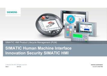
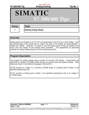
CPU moduleThe new S7-200 SMART has two different types of CPU modules, i.e. standard type and compact type.Standard type CPU is expandable with I/O expansion modules and signal boards. Compact type CPUsare non expandable with I/O expansion modules and signal boards.Standard type CPU moduleCPU SR20/SR30/SR40/SR60CPU ST20/ST30/ST40/ST60Ethernet interfaceCompact typeCPU moduleCPU CR40/CR60I/O expansion moduleRS485 serial portSignal board expansionSupporting Micro SD cardReal-time clock 1)High speed countersHigh speed pulse output2)1)2)TypeHigh speed counterCR40CR60SR20SR30SR404 at 100 kHz forsingle phaseSR60ST20Number ofcommunicationports22 3Number ofExpansion modules—6Maximumanalogue I/O3)3)660ST302 at100 kHz—40Only supports the standard type transistor output;ST40ST604 at 200 kHz for single phaseHigh speed pulseoutputMaximum I/Ohandling capacity 3)Only supports the standard type CPU module212222232—The maximum I/O handling capacity is considering I/O expansion with Signal boards.252212363 at 100 kHz222232252
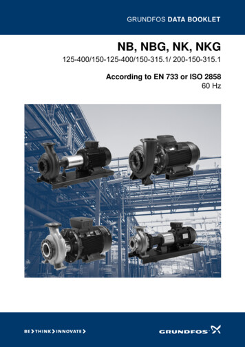
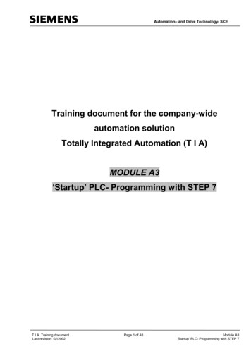
Communication and running stateindicator, the PLC state can be seen easily.Convenient installation,support rail type andscrew type installationThe input and outputterminals of all modulesare removable.Integrated Ethernetport that makes thedownloading andnetworking equipmentmore convenient;Pin plug connection,module can be connectedmore closelyGeneric Micro SD card supportsprogram downloading and PLCfirmware updatingSignal board extension achievesaccurate configuration, withoutoccupying space in the electriccontrol cabinet.Siemens dedicated highspeed chip is incorporated,with basic instructionexecution time up to 0.15 μs;It is equipped with supercapacitor, when the power isdown, it still can guaranteethe normal work of the clock7
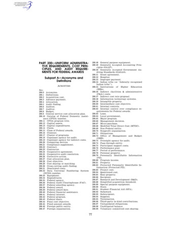
Signal boardThe signal board is mounted directly on the front of the CPU body; without occupying the cabinet space,its installation and disassembly are convenient and quick. For a small amount of I/O points extension andmore demand for communication ports, the signal board with new design can provide more economical andflexible solutions.Basic information of the signal boardModelSpecificationDescriptionSB DT042DI/2DOtransistor outputIt provides additional digital I/O extensions, and support2 digital inputs and 2 digital transistor outputs.SB AE011AIIt provides additional analog I / O expansion, andsupport 1Analog input , the precision is 12 bitsSB AQ011AOIt provides additional analogue I/O extension, andsupport 1 analogue output, with a precision 12 bits.SB CM01RS232/RS485It provides additional RS232 or RS485 serialcommunication interface, the conversion can berealized via simple configuration in the software.SB BA01Battery moduleIt supports the generic CR1025 cell (battery), which candrive the clock for about 1 year.Signal board configurationWhen the standard CPU module is selected in the system block, the aforementionedfour signal boards will display the SB options: When SB DT04 is selected, the system can automatically distribute I7.0 and Q7.0 as thebeginning of the I/O image area When SB AE01 is selected, the system can automatically allocates AIW12 as I / O imagearea When SB AQ01 is selected, the system can automatically allocates AQW12 as the I/Oimage area When SB CM01is selected, it can be done via selecting the RS232 or RS485 in the porttype setting box. When SB BA01 is selected, the low power consumption alarm can be initialized or thepower consumption state can be monitored via I7.0.Installation stepsRemove the cover board of terminal8Remove the cover board with ScrewdriverNo fastening screw is required,gently insert it;The installation is complete
Network communicationAll S7-200 SMART CPUs offer 1x Ethernet interface and the 1x RS485interface onboard. Using Signal board CM01, one can add additionalRS485/232 interface.Ethernet communicationSwitchAll the CPU modules are equipped with Ethernet interface, which supports Siemens S7protocol, can support many terminal connections:HMI1# PLC Can be used as the programs downloading port (via general network cable) Communicate with Simatic Key/touch HMI with Profinet/Ethernet interface, maximallysupport 8 sets of equipment Communicate with multiple Ethernet equipment through the switch to achieve fast datacommunication.2# PLC Supports up to 8 active GET/PUT connections and 8 passive GET/PUT connections.PROFIBUSWith EM DP01 expansion module S7 200 SMART CPU can be used in Profibus DP slavenetwork. Slave ID of the CPU can be selected from the rotary switch on the EM DP01module. The module supports any PROFIBUS baud rate between 9600 baud to 12M baud,the maximum allowable input 244Bytes and 244 output bytes.It supports the following protocols:1# PLC2# PLC MPI Slave PROFIBUS-DP slaveSerial communicationOn board RS485 port as well as additional RS232/485 port using CM01 can communicatewith the inverter and touch screen and so on third party equipments. Signal board offersconfigurable RS232/RS485 port, maximally supports for up to 4 devices.PLCHMISerial port supports the following protocols: Modbus RTU PPI USS Free port communication (for interconnection with Bar code scanners, weighing1 # servodrive2 # servodrive3 # servodrive1 # motor2 # motor3 # motorscales, serial printers etc.)OPC Communication (PC Access SMART)*Using Siemens PC Access SMART tool, it is possible to read/ write the data from S7-200SMART PLC on to the host computer. This can be used for simple GUI requirements fordata monitoring or data archiving.PC AccessSMART(PC Access SMART is an OPC server protocol specifically developed for S7-200 SMARTseries PLC, an OPC software dedicatedly developed for interaction between the S7-200SMART PLC and host computer)PLC*) please consult the Siemens offices and authorized distributors for the specific information.9
Motion controlS7-200 SMART CPU provides maximum three 100KHz high speed pulse outputs, it can be configured for PWM output ormotion control output through the powerful and flexible setup wizard, providing a unified solution for speed and positioncontrol of both the stepper motor or servo motor, satisfying the precise positioning requirements of the small mechanicalequipment.Basic functions of motion control Standard type transistor output module CPU, ST30/ST40/ST60 providesthree 100 kHz high speed pulse output (ST20 provides two 100 kHz),supports PWM (pulse width modulation) and PTO (pulse train output).PLC In PWM mode, the cycle of the output pulse is fixed, the pulse widthand duty cycle are adjusted by the program, which can adjust thespeed of the motor, the opening of valves etc.1# servo drive1 # motor2# servo drive3# servo drive2 # motor3# motor In PTO mode (motion control), the output pulse can be configuredas multiple modes of operation, including automatically finding theoriginal point, for realising the control of the stepper motor or servomotor, achieving the purpose of speed adjustment and positioning; The Q0.0, Q0.1 and Q0.3 on the CPU body can be configured as thePWM output or high speed pulse output, the above functions can beset up via the Wizard;PWM and motion control wizard settingsIn order to simplify the control functions in your application, theposition control wizard provided by the STEP 7- Micro/WIN SMARTcan help you complete the PWM and the PTO configuration in a fewminutes. The wizard can generate the position instructions, you candynamically control the speed and position in your application withthese instructions.According to the user selected PWM pulse number, the PWM wizardcan generate PWMx RUN subroutine frame corresponding to editing.Motion control wizards can maximally provide the settings for threepulse outputs, the pulse output speed is adjustable from 20 Hz to100 kHz.10
Typical ckingZ-axisHorizontalcuttingFilmfeedingLabelling machineY-axisPillow-type packaging machineWoodworking machineryMotion control features It provides configurable measurement system, it can use theengineering units (such as inches or centimetres) when inputting thedata, and can also use the pulse number. it provides configurable backlash compensation;Absolute positionSingle speed continuousrotationOn reaching RPS signalTarget speed stops0Startingendingposition it supports the absolute, relative and manual control modes; it supports the continuous operation;With stop trigger Single speedcontinuous rotationRelative positionControlled by the program, untilanother command is sent (suchas “terminating commands”Double Speed continuousrotation the target speed whenRPS is not activatedthe target speed whenRPS is activated it provides up to 32 groups of motion envelope, each envelope can setmaximally 16 levels of speed; it provides 4 different reference point searching modes, each mode canselect the initial direction search and the final approach direction.Statingending positionmeasured fromthe starting pointMonitoring of motion controlIn order to help users develop motion control scheme, STEP7- Micro/WIN SMART provides the motion control panel. Theoperation, configuration and envelope configuration settingslet the users easily monitor, on the motion control functionoperation, the start and test phases in the development process. The use of the motion control panel can verify whether themotion control wiring is correct or not, you can adjust theconfiguration data and test each mobile envelope; Display the current speed, current position and direction of thebit control, as well as the input and output of LED (except pulseLED) status; View to modify the configuration settings of the bit controloperation stored in the CPU module11
User-friendly software improves programmingefficiencySTEP 7- Micro/WIN SMART is the programming software of the S7-200 SMART, it can run smoothly on the Windows XPSP3/Windows 7 Operating System. It supports LAD (ladder diagram), STL (Statement List), FBD (function block diagram)programming languages, freely converting between parts of language, the installation file is less than 100 MB. Whileinheriting the excellent programming idea of the STEP 7- Micro/WIN, the more user-friendly design makes programmingeasier and project development more efficient.New menu designIt has no more traditional drop-down menu. It has adopted the band-typemenu design, all menu options can be seen completely. The image of theicon display makes the operation more convenient.By double clicking on the menu, it can be hidden so as to provide morespace for a visual programming window.Fully movable window designAll windows in the software interface can move freely, and provide eightkinds of drag and drop methods.The main window, the program editor, the output window, variable table,state diagram etc. windows can be combined according to the user'shabits, maximally improve the programming efficiency.The definitions of variables and program notesThe users can define the variable name according to the process flow, andcan call through the variable name directly, allowing users to fully enjoythe convenience of high-level programming language. A special functionregisters the address call, automatically naming the variable, which cannow be called directly the next time.Micro/WIN SMART provides a perfect function for annotation, can addannotations to program block, programming network and variables,with its readability greatly improved. When the mouse is moved to theinstruction block, data types supported by each pin are automaticallydisplayed.12
STEP 7-Micro/WIN SMART Software features:1. New menu design2. Fully movable window design3. Variable definitions and notes4. Novel wizard setting5. Status monitoring6. Convenient command Library7. Powerful password protection functions .For detailed information about the software, consult the S7-200 SMART SystemManual.Setup wizardMicro/WIN SMART integrates simple and quick wizard settings; you can just follow the wizardprompts to set up the parameters for each step of the complex function setting. The new guidancefunction allows the user to directly set up a step function, and without the need to reset every step,to modify the wizard settings.The wizard setting supports the following functions: HSC (high speed counter) Motion control PID PWM (Pulse width Modulation) Text displayStatus monitoringIn the Micro/WIN SMART status graph, it can monitor the current values of each input / outputchannel of PLC, at the same time, it can conduct the mandatory input operation to test the programlogic for each channel.Status monitoring value can be displayed in numerical form, and can also be directly displayed inthe waveform, the aforementioned two can also be switched each other.In addition, the Micro/WIN SMART system can monitor the PID and motion control operation,equipment operation status through the dedicate operation panel.Convenient command LibraryIn PLC programming, the same tasks that are repetitively executed will be generally included in asubprogram, which can be directly used in the future. The use of subroutines can better organizethe program structure, facilitate the debugging and reading.Micro/WIN SMART provides the command library functions, converting the subroutine into a blockof instructions, as a common block of instructions, which will be directly dragged and dropped intothe programming interface to complete the call. The command library function provides passwordprotection function, preventing the database files from being randomly reviewed or modified.In addition, Siemens offers a large instruction library to complete a variety of functions, which canbe easily added into the software.13
SMART micro automation solutionsThe perfect combination of Siemens SIMATIC micro-automation products and SINAMICS drive products has created new microautomation solutions that are economical, reliable and easy to use. SIMATIC S7-200 SMART PLC, SIMATIC BASIC LINE touch/Key HMI, SINAMICS V20 inverter and SINAMICS V90 servo system, that are of high performance-to-price ratio helps users toimprove the performance of machinery and equipment, reduce the development cost, significantly shorten the launchingtime of the machine and equipment, and effectively improve the market competitiveness of the user.SIMATIC Touch/Key HMIEthernetSIMATIC S7-200 SMARTSINAMICS V20USS/MODBUS RTUUSS / MODBUS RTUSINAMICS V90SIMOTICS GP 1LE0SIMOTICS S-1FL6Recommendations for the use of S7-200 SMART: While programming and debugging, it is suggested to, using 1 set of ordinary switchboard, to connect the related equipment (including PLC, touchscreen, computer) to the switch. After downloading the PLC or touch screen programs, they can be directly tested on the touch screen throughtouch. When testing the PLC working state, there is no need to use a cable to connect the PLC and touch screen. Through the use of Micro SD card the fast and batch downloading of the PLC program can be realized. The well-prepared source card can bedelivered to the end user by courier, or, in the scenario of urgent demand, the source file stored in the card can be sent via Email directly to the userat the site, the source file will be copied to the SD card and can be used after receiving.14
Common SD card – Fast Update!!The S7-200 SMART CPUs support the use of a microSDHC card for: User program transfer. Reset CPU to factory default condition. Firmware update of the CPU and attached expansion modules as supportedYou can use any standard, commercial microSDHC card with a capacity in the range 4GB to 16GB.For detailed information about thesoftware, consult the S7-200 SMART System Manual.Program TransferA memory card can be used to transfer user program content into theCPU's permanent memory, completely or partially replacing contentalready in the load memory.For duplication of program from one CPU to other CPUs, you need notrequire software. Time & cost saving is also achieved.Firmware upgradeA memory card can be used to update the firmware in a CPU and anyconnected expansion modules.No return to the factory for FW upgrade, it can be done with SD card.Restore factory settingsA memory card can be used to erase all retained data, putting the CPUback into a factory default condition.15
Technical specificationsTechnical specification for CPU SR20/ST20ModelCPU SR20 AC/DC/RLYCPU ST20 DC/DC/DCOrder No.: (MLFB)6ES7 288-1SR20-0AA06ES7 288-1ST20-0AA0StandardDimension W x H x D (mm)90 x 100 x 81Weight367.3 g320 gPower consumption14 W20WAvailable current (EM bus)Max. 740 mA (5 V DC)Max. 1110 mA (5 V DC)Available current (24 V DC)Max. 300 mA (sensor power source)Digital input current consumption (24 V DC)4mA for each input point usedCPU featuresUser memory12 KB program memory /8 KB data memory /max. 10 KB retentive memoryOn board digital I/O12 input points / 8 output pointsProcess image size256 bits input (I) / 256 bits output (Q)Analog image56 words input (AI) / 56 words output (AQ)Bit memory (M)256 bitsTemporary (local) memoryThe main program has 64 bytes, each subroutine and interrupt program has 64 bytesI/O module extension6 extension modulesSignal board extensionMax. 1 signal boardHigh speed counters4 in totalSingle phase: 4 of 200 kHzQuadrature phase: 2 of 100 kHzPulse output–Pulse capture input12Cycle interrupt2 in total, resolution is of 1ms,Interrupt Edge4 rising edges and 4 falling edges (when using optional signal board, there are 6 edges each)MemoryMicro SDHC card (optional)Precision of real-time clock120 seconds/monthReal-time clock hold timeIn general 7 days, or min. 6 days when 25 C (Maintenance free super capacitor)2 of 100 kHzPerformance/ Processing TimeBoolean0.15 μs/instructionMoving word operations1.2 μs/instructionReal mathematical operations3.6 μs/instructionThe user’s program elements supported by the S7-200 SMARTPOUsAccumulatorsTimerCounterstype/quantity main program: 1 sub-program: 128 (0 to 127) interrupt program: 128 (0 to 127)Nesting depth from main program: 8 sub-program level from interrupt program: 4 sub-program level4type/quantity non-holding (or not retained) (TON, TOF) : 192 holding (or retained) (TONR) : 64256CommunicationsNumber of ports1 Ethernet port/ 1 serial (RS485) /1 additional serial (optional RS232/485 signal board) portHMI equipmentmax. 4 connection on serial portmax. 8 connections on ethernet portEthernet: 1Ethernet: 8 for HMI 1 for programming 8 for CPU 8 for active GET/PUT connection 8 for passive GET/PUT connectionserial (RS485) : each port has 4 for HMI connectionsEthernet: 10/100 Mb/sRS485 system protocol: 9600, 19200 and 187500 b/sRS485 free port: 1200 to 115200 b/sEthernet: Transformer isolation, 1500 V ACRS485: noneEthernet: CAT5e shielded cableRS485: PROFIBUS network cableProgramming equipment (PG)Number of connectionsData transmission rateIsolation (external signal and PLC logic side)Type of cablePower sourceVoltage rangePower supply frequency1685 264 V AC47 63 Hz20.4 28.8 V DC–
Model (continued)Input currentInrush current (max)Isolation (input power with the logic side)Leakage current, AC line for functional earthingHold time (power off)Internal fuse (cannot be replaced by the user)Sensor power sourceVoltage rangeRated output current (max)Maximum ripple noise ( 10 MHz)Isolation (CPU logic side and sensor power source)Digital inputNumber of input pointsTypeCPU SR20 AC/DC/RLYWhen the maximum load is reached, only CPU is included210 mA when voltage is 120 V AC (with a 300 mA sensor power output)90 mA when voltage is 120 V AC (without a 300 mA sensor power output)120 mA when voltage is 240 V AC (with a 300 mA sensor power output)60 mA when voltage is 240 V AC (without a 300 mA sensor power output)When the max load is reached, it CPU and all the scalable extensions are included290 mA when voltage is 120 V AC170 mA when voltage is 240 V AC9.3 A when voltage is 264 V AC1500 V ACMax 0. 5 mA30 ms when voltage is 120 V AC200 ms when voltage is 240 V AC3 A, 250 V, Slow-blow fuse3 A, 250 V, Slow-blow fuse20.4 28.8 V DC300 mA (short circuit protection) 1 V peak-peak valueNot isolated12The sinking / sourcing type (IEC type 1 sinking)Rated voltageAllowable continuous voltageSurge voltageLogic 1 signal (min)It is 24V DC when the current is 4 mA, nominal valueMax 30 V DC35 V DC, lasting 0.5 sIt is 15 V DC when the current is 2.5 mALogic 0 signal (min)It is 5 V DC when the current is 1 mAIsolation (field side and logic side)Isolation groupFilter time500 V AC, lasting 1 min1Each channel can be separately selected (point I0.0 to 11.3) :0.2, 0.4, 0.8, 1.6, 3.2, 6.4 and 12.8 µs0.2, 0.4, 0.8, 1.6, 3.2, 6.4 and 12.8 msSingle phase: 4 of 200 kHzQuadrature phase: 2 of 100 kHz12Shielded: 500m (normal input), 50m (HSC input) ;non shielded: 300m (normal input)HSC clock input frequency (max)(Logic 1 battery 15 26 V DC)Number of inputs that connect at the same timeCable length (max), its unit is meterCPU ST20 DC/DC/DCWhen the maximum load is reached, only CPU is included160 mA when voltage is 24 V DC (without a 300 mAsensor power output)430 mA when voltage is 24 V DC (with a 300 mA sensorpower output)When the max load is reached, CPU and all the scalableextensions are included720 mA when voltage is 24 V DC11.7 A when voltage is 28.8 DC––20 ms when voltage is 24 V DCDigital outputNumber of outputTypeVoltage rangeLogic 1 signal when the current is max.Logic 0 signal when the load is KGRated current at each point (max)Rated current at each public end (max)Lamp loadOn state resistanceLeakage current at each pointSurge currentOverload protectionIsolation (field side and logic side)Isolation resistanceDisconnect the insulation between the contactsIsolated groupInductive voltage clampRelay max. on/off frequencySwitching delay (Qa.0-Qa.3)8Relay, dry contact5 30 V DC or 5 250 V AC––2.0 A10.0 A30 W DC/200 W ACNew equipment is 0.2 Ω maximally–It is 7A when the contact is closednone1500 V AC, lasting 1 min (coil and contact) none, (coil and logic side)New equipment is 100 MΩ minimally750 V AC, lasting 1 min1Not recommendedNot recommendedMax. 10 msSwitching delay (Qa.0-Qa.7)Max. 10 msMechanical life (no load)Contact life under the rated loadOutput state under the STOP modeNumber of output that are connected at the sametimeCable length10,000,000 break/close cycles100,000 break/close cyclesLast value or replicable value (The default value is 0)8The sinking/sourcing type (IEC type 1 sinking excludingI0.0 to I0.3)The voltage is 4 V DC when it ranges from I0.0 to I0.3,I0.6 to I0.7: 8 mAOther input: 15 V DC when it is 2.5 mAThe voltage is 1 V DC when it ranges from I0.0 to I0.3,I0.6 to I0.7: 1 mAOther input: 5 V DC when it is 1 mA.I0.0 to I0.3, shielded (only limited to this category) :500 m (normal input), 50 m (HSC input)I0.6 to I0.7, shielded (only limited to this category) :500 m (normal input),All other inputs: shielded: 500 m (normal input) ;non shielded: 300 m (normal input)Solid state-MOSFET (source-type)20.4 28.8 V DCMin. 20 V DCMax. 0.1 V DC0.5 A6A5WMax. 0.6 ΩMax. 10 µ A8 A, max. lasting 100 ms500 V AC, lasting 1 min––2L - 48 V DC, 1 W lossFrom the disconnection to connection max.1 µsfrom the connection to disconnection is 3 µs max.From the disconnection to connection max. 50 µsfrom the connection to disconnection is 200 µs max.––Shielded: 500 m; non shielded: 300 m17
Technical specification for CPU SR30/ST30ModelCPU SR30 AC/DC/RLYCPU ST30 DC/DC/DCOrder No.: (MLFB)6ES7 288-1SR30-0AA06ES7 288-1ST30-0AA0StandardDimension W x H x D (mm)110 x 100 x 81Weight435 g375 gPower consumption14 W12WAvailable current (EM bus)Max. 740 mA (5 V DC)Available current (24 V DC)Max. 300 mA (sensor power source)Digital input current consumption (24 V DC)4mA for each input point usedCPU featuresUser memory18 KB program memory /12 KB data memory /max. 10 KB retentive memoryOn board digital I/O18 input points / 12 output pointsProcess image size256 bits input (I) / 256 bits output (Q)Analog image56 words input (AI) / 56 words output (AQ)Bit memory (M)256 bitsTemporary (local) memoryThe main program has 64 bytes, each subroutine and interrupt program has 64
SIMATIC S7-200 SMART, our newly launched micro PLC product, is designed to suit the needs of developing markets that are under constant pressure due to prices and demands for continuous performance. Providing an excellent performance-to-price ratio, SIMATIC S7-200 SMART when combined with