Transcription
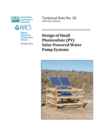
Traffic Lighting Design ManualDelivery & Operations Division Traffic Roadway SectionFebruary 2022
Traffic-Roadway SectionTraffic Lighting Design ManualODOT is an Equal Employment Opportunity and Affirmative Action Employer.This information can be made available in alternative format by contacting 503-986-3568. ODOTdoes not discriminate on the basis of disability in admission or access to our programs, services,activities, hiring and employment practices. Questions: 1-877-336-6368 (EEO-ODOT) or throughOregon Relay Service at 7-1-1.Oregon Department of TransportationEngineering & Technical Services BranchTraffic-Roadway Section, MS#54040 Fairview Industrial Drive SESalem, Oregon 97302503-986-3568Traffic Engineering WebsiteFebruary 2022page i
Traffic-Roadway SectionTraffic Lighting Design ManualTable of Contents1.0 – Introduction .11.1 – Availability. 11.2 – Updates. 12.0 – Starting the Design .22.1 – What Standards Will Be Used?. 22.1.1 – Full ODOT Design Standards and Specifications . 22.1.2 – Local Agency Design Standards and Specifications . 22.2 – Background Information to Gather . 22.2.1 – As-Built Drawing Archive (FileNet) . 22.2.2 – Electronic Information . 22.2.3 – Field Verification . 32.3 – Background Information from Others . 32.3.1 – Base Map and Survey Information . 32.3.2 – Roadway Design . 32.3.3 – Geotechnical Report . 32.3.4 – Utility Hook-ups. 32.4 – Illumination Design Project File . 43.0 – Lighting Analysis .53.1 – Standard Calculations . 53.2 – Optional Calculations . 54.0 – Illumination Plan .74.1 – Pole Placement. 74.2 – Standard Lamps . 74.3 – Standard Luminaires . 85.0 – Poles and Towers .9February 2022page ii
Traffic-Roadway SectionTraffic Lighting Design Manual6.0 – Power Supply .107.0 – Power Distribution System .118.0 – Temporary Lighting.139.0 – Partial Interchange Lighting .1510.0 – Underpass and Tunnel Lighting .1610.1 – Underpass Lighting . 1610.2 – Tunnel Lighting . 1611.0 – Lighting for Intersections and Crosswalks .1711.1 – Intersections . 1711.1.1 – Full Intersection Lighting . 1711.1.2 – Intersection with One-way Illumination. 1711.1.3 – Isolated Intersection Lighting . 1811.2 – Marked Crosswalks at Intersection . 1811.3 – Marked Midblock Crosswalks . 1911.3.1 – Marked Midblock Crosswalks without Traffic Control Device . 1911.3.2 – Marked Midblock Crosswalks with Beacons . 2011.4 – Evaluation of Existing Lighting . 2011.4.1 – Computer Analysis . 2011.4.2 – Field Measurement . 2112.0 – Sign Lighting .2513.0 – Aviation and Navigation Lighting .2613.1 – Navigation Lighting . 2613.2 – Aviation Lighting . 2614.0 – Monthly System Energy Utilization.2715.0 – Standard Drawings and Details .28February 2022page iii
Traffic-Roadway SectionTraffic Lighting Design Manual15.1 – Standard Drawings . 2815.2 – Standard Details . 2816.0 – Specifications, Bid Items and Cost Estimate .3016.1 – Review and Approval of the Special Provisions . 3016.2 – Bid Items . 3016.2.1 – Permanent Illumination Bid Items (00970.90) . 3116.2.2 – Removal of Electrical Systems Bid Items (00950.90) . 3116.2.3 – Temporary Illumination Bid Items (00227.90) . 3216.3 – Cost Estimate . 3216.3.1 – Anticipated Items . 3217.0 – Construction Support .3318.0 – Additional Resources .34February 2022page iv
Traffic-Roadway SectionTraffic Lighting Design Manual1.0 – IntroductionThe purpose of the Traffic Lighting Design Manual is to assist in the lighting design of futureconstruction and reconstruction projects on state highways. It is not intended that existinglighting systems be modified as a result of this manual. For policy practices, please refer to theLighting Policy and Guidelines.This design manual draws from several sources, cited in the Additional Resources section ofthis manual. This manual addresses items not included in the AASHTO Roadway LightingDesign Guide or provides clarification on included items.The material herein is for informational purposes only and may aid new employees and thoseunfamiliar with ODOT traffic engineering and design practices. The state illumination engineeris responsible for maintaining ODOT’s Traffic Lighting Design Manual.Contact information is:Ernest Kim, P.E.State Illumination EngineerPhone: 503-986-3587Mobile: 503-476-7941Ernest.C.Kim@odot.oregon.gov1.1 – AvailabilityThis manual is a web-only document. You may access and print in its entirety from the g/Documents Manual.pdf1.2 – UpdatesThe state illumination engineer updates this manual continually; revisions will be made asnecessary. The revised manual becomes effective on the official revision date (month/yearformat). All design work prior to final plans should follow the requirements of the currentversion of this manual.February 2022page 1
Traffic-Roadway SectionTraffic Lighting Design Manual2.0 – Starting the DesignBefore starting the design, gather the following information: Standards applied to the project Applicable project background information, such as roadway, bridge and signalinstallation Illumination project scope2.1 – What Standards will be Used?Designers must answer the question “what standards will I use” before starting the design andspecifications. Investigating and gathering applicable standards for the assigned project areessential part of successful outcome. Regardless of the jurisdiction, illumination installationmust meet the current National Electrical Code.2.1.1 – Full ODOT Design Standards and SpecificationsFull ODOT standard consists of the ODOT Lighting Policy and the ODOT Traffic LightingDesign Manual. The full standard is typically required for any project on the state highwaysystem outside of city limits. If ODOT will maintain and operate the illumination system, thefull standard is always required.2.1.2 – Local Agency Design Standards and SpecificationsThe local agency standard applies to local agency owned and maintained illumination systemon the state highways. If the local agency will maintain and operate the state ownedillumination system then ODOT may allow local agency standards.2.2 – Background Information to Gather2.2.1 – As-Built Drawing Archive (FileNet)As-built plan sheets will be available from ODOT traffic or illumination designer, or electricalcrew. Also, they are available from FileNet in ODOT website. There is a Traffic Plan SearchGuide available on FileNet for help using the database.2.2.2 – Electronic InformationPrior to field verification, it is good to get familiar with the project area using availableelectronic sources, such as ODOT digital video logs and Google maps. These tools can helpidentify issues to address during the field verification.February 2022page 2
Traffic-Roadway SectionTraffic Lighting Design Manual2.2.3 – Field VerificationField verification is an important step in the process of designing illumination.Making a field visit during the design phase and verifying the existing conditions could save alot of cost and effort during the construction phase of the project. It provides the designeraccurate and complete information of existing conditions.The designer may ask the electrical crew for assistance accessing certain portions of the existingillumination system.2.3 – Background Information from Others2.3.1 – Base Map and Survey InformationFor new pole installations, illumination design requires a full survey information and ageotechnical report. Collect the following data within the survey area: Underground utilities less than 10 ft. deep in project area. Above ground utilities and wires with existing heights. Power poles with transformers for power sources. All pavement markings within the survey area. Any illumination and electrical wiring on bridges and wall structures. Any other existing illumination within the survey area.2.3.2 – Roadway DesignIf the project involves rebuilding or modifying the roadway, there will be a roadway base mapshowing the final roadway layout. It is critical that the illumination design is based on what thecrew will build in the field.The illumination designer must communicate with the roadway designer from the start ofdesign through final plans. The roadway designer’s final product, including bridges and wallstructures, is the base for the illumination design.2.3.3 – Geotechnical ReportIf new poles are proposed, then a geotechnical report is required to determine the foundationdepths. Contact the region geo/ hydro manager for a foundation investigation of the proposedsite as soon as the pole locations are defined.2.3.4 – Utility Hook-upsNew illumination systems require a connection to a commercial power source. It may involvemoving existing utilities.February 2022page 3
Traffic-Roadway SectionTraffic Lighting Design ManualThe illumination designer needs to coordinate with the region utility specialist and utilitycompany when locating the power supply and requesting any new connections early in thedesign process.2.4 – Illumination Design Project FileUse ProjectWise to store the project files for the illumination design. It should contain thesupporting documents, calculations and decisions related to the illumination design andconstruction. The items listed below, if applicable, are typically included in the files: Project narratives with project scope. Photometric data file of the luminaires. Project plan sheets and comments log. Calculations for:oElectrical load.oWire sizes.oIllumination light levels.oVoltage drop.oTypical energy usage. Cost estimates (itemized breakdown for each bid item, total bid item cost, andanticipated item cost). Emails and memos related to illumination design decisions. Photos. Field verification information. Geotechnical report. Pole submittals and shop drawings. Manufacturer’s cut-sheets and submittals of electrical materials. Correspondence between project managers, consultants or contractors. Existing “As-builts”.February 2022page 4
Traffic-Roadway SectionTraffic Lighting Design Manual3.0 – Lighting AnalysisIt is ODOT’s practice to provide adequate illumination levels on the roadway according to thenational standards, listed in Chapter 18.3.1 – Standard CalculationsODOT uses the illuminance method for light level calculation. The lighting design and itscalculations shall meet the required average maintained illuminance level and average tominimum uniformity stated in national standards (see Chapter 18).The lighting analysis should include the following information:A. Provide average illuminance level in foot-candle (fc) or luxB. Check minimum point.C. Check maximum point.D. Check illuminance uniformity ratios.a. Average to minimum.b. Maximum to minimum (10:1 or less is desirable).E. Uniformity of illumination using mean deviation (for sign lighting).Provide increased illumination levels at critical decision points of the roadway. Some examplesof critical decision points are:A. Gore areas - 1.0 to 1.5 fc.B. Weaving lanes - 0.8 to 1.0 fc average.C. Intersections (see Chapter 11).D. Underpasses (up to 1.5 times of roadway illuminance level).Glare and veiling luminance at critical decision points of the roadways should also be checkedto satisfy design requirements (maximum of veiling luminance ratio is 30- 40%).On ODOT plans, include the average maintained illuminance and average to minimumuniformity on the first page of the illumination plans.3.2 – Optional CalculationsAs appropriate, use the luminance method for light level calculation when designingillumination system for a corridor. The unit is candela per square meters (cd/m2).Recommended values are according to RP-8-18, Table 10-1 and Table 11-1.Check average maintained luminance level with:February 2022page 5
Traffic-Roadway SectionTraffic Lighting Design ManualA. Uniformity of luminance (average to minimum).B. Veiling luminance ratio (maximum to average).February 2022page 6
Traffic-Roadway SectionTraffic Lighting Design Manual4.0 – Illumination Plan4.1 – Pole PlacementUse engineering analysis and judgement to minimize the number of poles needed to meet thelighting requirements of the project. All equipment (including foundations) must be locatedwithin the right of way or permanent easements.When working on illumination located near airports, there is the possibility of heightrestrictions, which can have an impact on pole locations and parameters.Also, consider permitted high loads and oversized truck routes. Check with the airportregarding flight paths and any height restrictions and with the ODOT trucking industryrepresentative regarding permitted route issues.Always check for possible conflicts with overhead and underground utilities when placingillumination poles. Address conflicts with overhead and underground utilities during thedesign phase.Designs must meet a minimum clearance requirement from overhead high voltage lines, perOAR 437-002-0047, National Electrical Safety Code and other regulations. If there are knownconflicts with utilities, contact the region utility specialist for assistance. Address and resolveutility conflicts before the design is complete.Slip base poles are installed mainly for freeway environment. The designer should investigatetraffic condition and frequency of pedestrians of the project area to ensure traffic safety. Slipbase pole installation is not recommended around sidewalks, commercially developed area orintersections.Fixed base poles should be installed outside of “clear-zone distance” required per AASHTO’s“Roadside Design Guide.” With appropriate protection in front of fixed pole location such asbarriers, walls or guardrails, fixed base poles can be installed closer to the roadway and trafficarea.4.2 – Standard LampsIt is ODOT’s standard to use light emitting diode (LED) lamps on all new installations ownedand maintained by ODOT maintenance. Access specifications for LED luminaires installed on“Cobrahead” style poles in standard specifications 00970.45 and 02926.54. Coordinate with thestate illumination engineer and maintenance crew to select the appropriate LED luminaireswhen designing illumination mounted on structures other than standard poles.February 2022page 7
Traffic-Roadway SectionTraffic Lighting Design Manual4.3 – Standard LuminairesStandard luminaires for ODOT projects are LED luminaires along state highways and bridges,including tunnels and underpass installation. Exceptions may occur when a region trafficengineer allows the use of other light sources such as high pressure sodium (HPS) or metalhalide luminaires.Establish the pole spacing by evaluating the luminaire’s photometric performance, wattagesand other parameters, such as mounting height, hang-over distance etc. You may determinethese luminaire wattage and pole parameters with the lighting analysis described in Chapter 3.The high-mast luminaire may be used for interchange lighting. Use the cut-off style of luminairein these applications to control light trespass. LED luminaires, which are up to 500 watt each,can be used and the weight of each luminaire should be equal to or less than 50 lb. In the past,ODOT has used 400 to 1000 watt high pressure sodium (HPS) lamps for these applications, andthe illumination designer can replace existing luminaires with the same kind, if necessary.Mount underpass luminaires on bridge structures. When the luminaire is recessed into the boxgirder, use an underdeck style luminaire with 70-100 watt HPS or 40-70 watt LED. When theluminaire is located on the open beam or girder type structures, use a pendant mount styleluminaires with integral ballast. When the luminaire is on a rigid frame, or overcrossing bents,use the wall mount style luminaire with glare shield. Even though HPS fixtures have been usedfor these applications, the designer should coordinate with the maintaining agency to determineif LED luminaires is preferable.Typically, ODOT uses the boxy style LED luminaire for bikeway and pedestrian paths. Therecommended minimum mounting height is 30 feet. Lower mounting heights are subject tovandalism. Vandal resistant types of lighting installations are preferred. Since local agenciesgenerally maintain and operate bikeway and pedestrian path lighting, the designer shouldcoordinate with the local agency for its preferences.February 2022page 8
Traffic-Roadway SectionTraffic Lighting Design Manual5.0 – Poles and TowersChoose poles and tower locations to provide traffic safety as well as required light levels anduniformities. Use ODOT-approved poles and towers when installing illumination on the statehighway system.For typical “cobra-head” installations, use galvanized steel poles with slip or fixed base. Slipbase steel poles can be installed within the clear zone. Fixed base poles must be outside the clearzone or behind a protective barrier.The general recommendation for pole placement on highways is 30 ft. from the edge of thetravel lane where no barriers are installed. When a barrier is present, place poles 5 ft. behind theface of the barrier.Typically, ODOT uses a mounting height of 40 ft. However, designers may consider othermounting heights depending on the project site and results of the illumination analysis. Whendetermining the mounting height, consider the following factors: Highways in urban area. Controlling trespass light. Interference with the view of property owners (when poles located near property linebetween owners). Effecting greenhouses, mink farms, etc. Overhead conflict with utility lines or structure. Up to 50 foot mounting height can be used where needed in case of replacing existingpole or covering wider roadways.ODOT typically surveys illumination poles into place during construction. Designers need afinished cross section at each pole location in order to have a realistic estimate of the attachmentheight and base height of the pole. If the construction schedule does not allow the necessarylead time (approximately six months) to order the poles, crews may pre-order the poles usingthe base height and attachment height. The designer should coordinate with the project leaderand the construction project manager if it is necessary to pre-order poles.When installing high-mast tower illumination, use galvanized steel towers. Traffic StandardsUnit must approve all high mast illumination installations. Contact and coordinate with thestate illumination engineer prior to DAP design.For lighting outside ODOT jurisdiction: Check with city, county and related utilitycompany for their design requirements or preferences.February 2022page 9
Traffic-Roadway SectionTraffic Lighting Design Manual6.0 – Power SupplyODOT powers all highway illumination systems with commercial power. Select the nearestpower source location with available utility’s information. Illumination system needs to tappower from a transformer. If illumination design requires a new transformer installation, checkand coordinate with utility company.It is important to investigate what type of power is available and where the power source islocated. Typically 120/240 volts single phase power is used, but 240/480 volt three phase powercan be used on larger electrical system (such as interchange illumination system) and tunnellighting. If the existing power source is inadequate, inform the region utility specialist so theycan work with the utility company to upgrade the power source.Sometimes a project requires moving the existing power source to a new location. If this is thecase, illumination designer must work with utility company in advance and show this changein the illumination plans.For new installations, the wiring from the power source should enter into the service cabinet viaa conduit (aerial connections are not recommended for permanent illumination system). Thedesign and installation of the conduit and wiring from the power source to the service cabinet isaccording to the requirements of the power company. The plan sheets should include areference to the conduit and wiring indicating this requirement.Generally, the contractor is responsible for installing the conduit and a pull-line from the servicecabinet to the power source. The power company is responsible for installing and terminatingthe wiring from the service cabinet to the power source.The cost of the power hook-up is included as an ‘”Anticipated Item” in the project.February 2022page 10
Traffic-Roadway SectionTraffic Lighting Design Manual7.0 – Power Distribution SystemElectrical power is distributed to the illumination system via conduit and conductors (copperwires). Locate the control cabinet near the center of the system. Use the simplest layout tominimize conduit/conductors length and voltage drop occurring to the farthest location of theelectrical circuit from the cabinet.The maximum system voltage drop shall be under 5% per National Electrical Code (NEC). ForODOT illumination systems, the recommended value of the maximum voltage drop on thebranch circuits is 4% and the maximum voltage drop between the utility transformer andservice cabinet is 1%.The typical formula for voltage drop (using NEC Table 9) is:𝑉𝑉𝑑𝑑 Where:(2 𝐴𝐴 𝐿𝐿 𝑅𝑅)1,000𝑉𝑉𝑑𝑑 Voltage drop (single phase AC system).2 Power goes out and back using two wires.A Load being drawn (amperes).L Wire distance (ft.).R Resistance per 1,000 feet (ohms).Determine the load, A, by dividing the total wattages connected down the stream, by thevoltage serving the load. Calculate the percentage drop by dividing total voltage drop in acircuit by service voltage, and then multiplying them by 100.Calculate voltage drop in three phase AC system with:𝑉𝑉𝑑𝑑,3 𝑝𝑝ℎ𝑎𝑎𝑎𝑎𝑎𝑎 (1.732 𝐴𝐴 𝐿𝐿 𝑅𝑅)1,000On ODOT installations, the minimum wire size is #10 AWG copper.Junction boxes provide pull point and secure splicing room for circuits coming from the servicecabinet to the poles. Provide a concrete junction box at each illumination pole and provide aconduit sweep into the pole with smaller conductors.Space junction boxes a maximum of 300 ft. apart on a conduit run. The total conduit diametercontained within the junction box determines the size of the junction box. Use polymer concretefor the illumination junction box lids.It is also important to consider the type of surface on which the crew will install a junction box.The ”A” in the junction box designation denotes a 12-inch wide concrete apron surrounding aFebruary 2022page 11
Traffic-Roadway SectionTraffic Lighting Design Manualprecast concrete junction box. The concrete apron provides support to the fragile sides of thebox. Use a type “A” boxes in non-paved areas, where maintenance vehicles may be present.Do not use a precast concrete junction box within a travel lane or any access area, exposed totraffic. Avoid placing a junction box within a travel lane or where it is exposed to traffic at allcosts. However, designers must use an approved cast iron junction box, rated for traffic, forlocations where we cannot avoid traffic exposure. Do not place junction boxes in the slope orthe landing area of an ADA ramp. Standard detail DET4320 shows illumination junction boxesand the installation guidelines.A pad mounted control cabinet shown in standard drawings TM302 and TM303 are thestandard for new illumination installations. The main circuit breaker must be rated 600 volts(except for 120-volt system use circuit breaker rated 480 volts). Branch circuit breaker ratings areas follows:1. For 120-volt system, use 277-volt rated circuit breakers.2. For 240-volt system, use 480-volt rated circuit breakers.3. For 480-volt system, use 480-volt rated circuit breakers.Short circuit interrupt rating: All service equipment and circuit breakers must have equal orhigher ratings than available fault currents of the system.Provide separate circuit(s) for sign illumination, naviga
AASHTO’s “Roadside Design Guide”. 4.2 Standard Lamps It is ODOT’s standard to use light emitting diode (LED) lamps on all new installations that are owned and maintained by ODOT maintenance. Specifications for LED luminaires installed on “Cobrahead” style poles can be foun
