Transcription
William StallingsData and ComputerCommunicationsChapter 4Transmission MediaTransmission Medium Physical path between transmitter & receiver Guided - wire Unguided - wireless Characteristics and quality of data transmissiondetermined by medium and signal For guided transmission, the medium is more important For unguided transmission, the bandwidth produced bythe antenna is more important Signal directionality Lower frequency signals are omnidirectional Higher frequency signals can be focused in a directional beam1
Transmission System DesignFactors Key concerns are data rate and distance Bandwidth Higher bandwidth gives higher data rate Transmission impairments Attenuation Interference Can be minimized by proper shielding in guidedmedia Number of receivers In guided media, more receivers (multi-point)introduce more attenuation and distortionElectromagnetic Spectrum2
Guided Transmission Media Transmission capacity depends on distance andtype of network (point-to-point or multipoint) Types of guided transmission media Twisted Pair Coaxial cable Optical fiberTwisted Pair Least expensive and most widely used Two insulated copper wires arranged in regularspiral pattern Number of pairs bundled together in a cable Twisting decreases crosstalk interferencebetween adjacent pairs in cables Using different twist length for neighboring pairs3
Twisted Pair - Applications Most common transmission medium for bothanalog & digital signals Telephone network Between house and local exchange (subscriber loop) Within buildings Telephones connected to private branch exchange(PBX) for voice traffic Connections to digital switch or digital PBX (64kbps) For local area networks (LAN) 10Mbps or 100MbpsTwisted Pair - Pros and Cons Advantages Cheap Easy to work with Disadvantages Low data rate Short range4
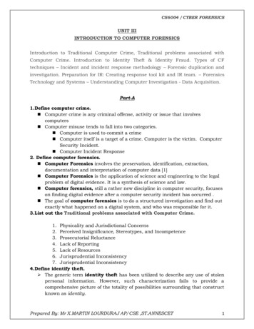
Twisted Pair - TransmissionCharacteristics Analog transmission Amplifiers every 5km to 6km Digital transmission Use either analog or digital signals repeater every 2km or 3km Attenuation is a strong function of frequency Susceptible to interference and noise Easy coupling with electromagnetic fields A wire run parallel to power line picks up 60-Hzenergy Impulse noise easily intrudes into twisted pairsAttenuation of Guided Media30Attenuation (dB/km)1024-gaugetwisted pair(0.5 mm)3/8" coaxialcable (0.95 cm)31opticalfiber0.30.11 kHz1 MHz1 GHz1 THz1000 THzFrequencyFigure 4.3Attenuation of Typical Guided Media5
Twisted Pair - TransmissionCharacteristics Measures to reduce impairments Shielding with metallic braids or sheathing reduces interference Twisting reduces low frequency interference Different twist length in adjacent pairs reduces crosstalk Limited distance Limited bandwidth For point-to-point analog signaling, 1MHz Limited data rate For long distance digital point-to-point signaling, 4 Mbps For very short distances, 100Mbps-1GbpsUnshielded and Shielded TP Unshielded Twisted Pair (UTP) Ordinary telephone wire Cheapest Easiest to install Suffers from external EM interference Shielded Twisted Pair (STP) Metal braid or sheathing that reduces interference Better performance at higher data rates More expensive Harder to handle (thick, heavy)6
Unshielded Twisted-Pair (UTP) Quality of UTP vary from telephone-grade wire toextremely high-speed cable Cable has four pairs of wires inside the jacket Each pair is twisted with a different number of twistsper inch to help eliminate interference The tighter the twisting, the higher the supportedtransmission rate and the greater the cost per footUTP Categories Cat 3 up to 16MHz Voice grade found in most offices Twist length of 7.5 cm to 10 cm Cat 4 up to 20 MHz Cat 5 up to 100MHz Commonly pre-installed in new office buildings Twist length 0.6 cm to 0.85 cm7
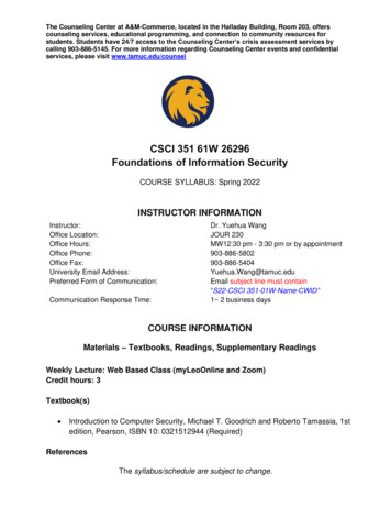
Unshielded Twisted PairConnector The standard connector for unshielded twistedpair cabling is an RJ-45 connector. A plastic connector that looks like a large telephonestyle connector RJ stands for Registered Jack; connector follows astandard borrowed from telephone industry. Standard designates which wire goes with each pininside the connector.Cat 5 Network CablesCategory 5 Cable composedof 4 twisted pairsCat 5Cable RJ45composed of 4 twisted pairsShielded Cat 5 NetworkCable RJ458
Near-End Cross Talk (NEXT) When current flows in a wire, anelectromagnetic field is created which caninterfere with signals on adjacent wires. As frequency increases, this effect becomesstrongerNear-End Cross Talk (NEXT) Each pair is twisted because this allows opposing fieldsin the wire pair to cancel each other. The tighter the twist, the more effective the cancellation, and thehigher the data rate supported by the cable. Maintaining this twist ratio is the single most important factor inany successful UTP installation If wires are not tightly twisted, the result is near end crosstalk(NEXT). NEXT is the portion of the transmitted signal that iselectromagnetically coupled back into the receivedsignal.9
Near-End Cross Talk (NEXT) NEXT is a measure of difference in signalstrength between a disturbing pair and adisturbed pair. A larger number (less crosstalk) is moredesirable than a smaller number (morecrosstalk). Because NEXT varies significantly withfrequency, it is important to measure it across arange of frequencies, typically 1 – 100 MHz.Comparison of Shielded &Unshielded Twisted PairAttenuation (dB per 100m)Near-End Crosstalk (dB)Frequency(MHZ)Cat. 3UTPCat. 5UTP150-ohmSTPCat. 3UTPCat. 021.431.310
Coaxial Cable Hollow outer cylindrical conductor surrounding asingle inner conductor Inner conductor held by regularly spacedinsulating rings or solid dielectric material Operates at higher frequencies than twisted pairCoaxial Cable Outer conductor covered with a jacket or shield Diameter from 1 to 2.5 cm Shielded concentric construction reducesinterference & crosstalk Can be used over longer distances & supportsmore stations on a shard line than twisted pairSolid metalinner corePlastic insulator- usually whiteFoil shieldBraidedshield/outerconductorPlastic or vinyljacket11
Coaxial Cable Applications Most versatile medium Television distribution Ariel to TV Cable TV Can carry hundreds of TV channels for tens of kms Long distance telephone transmission Can carry 10,000 voice channels simultaneously Being replaced by fiber optic Short distance computer systems links Local area networksCoaxial Cable - TransmissionCharacteristics Used to transmit both analog & digital signals Superior frequency characteristics compared to twistedpair (1KHz-1GHz) Less susceptible to interference & crosstalk Constraints on performance are attenuation, thermalnoise, intermodulation noise Analog Amplifiers every few km Closer spacing if higher frequency Up to 500MHz Digital Repeater every 1 to 9 km Closer spacing for higher data rates12
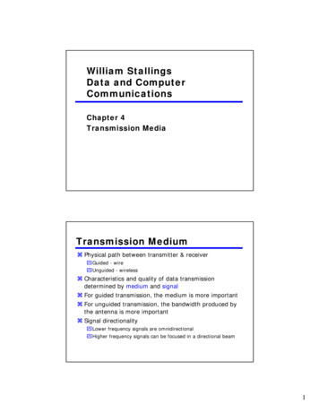
Optical Fiber Thin, flexible material to guide optical rays Cylindrical cross-section with three concentriclinks Core Innermost section of fiber One or more very thin (diameter 8-100 µm) strandsor fibers Cladding Surrounds each strand Plastic or glass coating with optical propertiesdifferent from core13
Optical Fiber Jacketdiameters Outermost layer, surrounding one or more claddings Made of plastic and other materials Protects from environmental elements like moisture,abrasions and crushingGlass coreGlass cladding50 microns62 microns100 micronsMultimode125 microns125 microns140 microns2-8 micronsSinglemodePlastic or vinyl jacketNote: A micron is a millionth of a meterOptical Fiber14
Optical Fiber - Benefits Greater capacity Data rates of hundreds of Gbps over tens of Kms Smaller size & weight Significantly lower attenuation Electromagnetic isolation Not affected by external EM fields Not vulnerable to interference, impulse noise, or crosstalk No energy radiation; little interference with other devices;security from eavesdropping Greater repeater spacing 10s of km at least Lower cost and fewer error sourcesOptical Fiber - Applications Long-haul trunks Increasingly common in telephone networks About 1500 km in length with high capacity (20,000-60,000voice channels) Metropolitan trunks Average length of about 12 km with capacity of 100,000 voicechannels Mostly, repeaters not required Rural exchange trunks Lengths from 40 to 160 km with fewer than 5000 voice channels Subscriber loops Handle image, video, voice, data LANs 100 Mbps to 1 Gbps, support hundreds of stations on campus15
Optical Fiber - TransmissionCharacteristics Single-encoded beam of light transmitted by totalinternal reflection Fiber has two basic types, multimode and singlemode Multimode fiber means that light can travel manydifferent paths (called modes) through the core of thefiber, which enter and leave the fiber at various angles. highest angle that light is accepted into the core of the fiberdefines the numerical aperture (NA). Transparent medium should have higher refractive indexthan surrounding medium Refractive index: ratio of speed of light in vacuum to speed oflight in medium Act as wave guide for frequency 1014 to 1015 Hz Portions of infrared and visible spectrumOptical Fiber – Light Sources Semiconductor devices that emit light when voltageapplied Light Emitting Diode (LED) Cheaper Wider operating temp range Longer operational life Injection Laser Diode (ILD) More efficient Greater data rate Wavelength Division Multiplexing (WDM) Multiple beams of light at different frequencies transmittedsimultaneously 100 beams operating at 10 Gbps, for a total of 1 trillion bps16
Optical Fiber TransmissionModes Step-index multimode Core made of one type of glass Light traveling in fiber travels in straight lines, reflecting off thecore/cladding interface Rays at shallow edges reflected and propagated along fiber Other rays absorbed by surrounding material Allows for multiple propagation paths with different path lengthsand time to traverse fiber A pulse of light is dispersed while traveling through the fiber Limits rate at which data can be accurately received Best suited for transmission over very short distancesOptical Fiber TransmissionModes17
Graded Multimode Fiber Core is composed of many different layers of glass, withindices of refraction producing a parabola index profile A properly constructed index profile will compensate forthe different path lengths of each mode Bandwidth capacity of graded fiber 100 times largerthan step index fiber Normally uses inexpensive LED laser transmitter andreceiver Maximum distance up to 2 km Most common type is 62.5/125µm Uses wavelengths of 850nm and 1300nm Often used for building backbones and short interbuilding communicationsGraded Multimode Fiber Higher refractive index at center makes rays close to axis advanceslower than rays close to cladding Light in core curves helically reducing traveling distance (does notzigzag off cladding) Shorter path & higher speed makes light at periphery as well asaxis travel at same speed18
Single-Mode Fiber Shrinks core size to a dimension about 6 times the wavelength ofthe fiber, causing all the light to travel in only one mode Modal dispersion disappears and bandwidth of the fiber increasesby at least a factor of 100 over graded index fiber Can be used for distances of 30 km or when high data rates arerequiredFiber Optic Attenuation Attenuation of optical fiber is a result of two factors,absorption and scattering Absorption is caused by absorption of light andconversion to heat by molecules in the glass. Absorption occurs at discrete wavelengths, and occursmost strongly around 1000 nm, 1400 nm and above1600 nm. Scattering occurs when light collides with individualatoms in the glass Light scattered at angles outside the numerical apertureof fiber will be absorbed into the cladding or transmittedback toward the source.19
Fiber Optic Attenuation Scattering is a function of wavelength, proportional toinverse fourth power of wavelength of light doubling wavelength of light, reduces scattering losses 16 times For long distance transmission, use longest practicalwavelength for minimal attenuation and maximumdistance between repeaters Fiber optic systems transmit in the "windows" createdbetween the absorption bands at 850 nm, 1300 nm and1550 nm Plastic fiber has a more limited wavelength band, thatlimits practical use to 660 nm LED sourcesFiber Optic Attenuation20
Fiber Types and TypicalSpecificationsFiber TypeCore/CladdingDiameter.(microns)850 nm1300 nm1550 nm(MHz-km)Step 00Singlemode8-9/125NA0.50.3highPlastic1 mm(1 dB/m @665 nm)Attenuation Coefficient(dBkm)Bandwidth@ 1300 nmLowFiber Optic CablesFiber optic cableDuplex Multimode62.5/125 µmDuplex Singlemode9/125 µm21
Point-to-Point TransmissionCharacteristics of Guided epeaterSpacingTwisted Pair(with loading)0 to 3.5 KHz0.2 dB/km@1kHz50 us/km2 kmTwisted Pair(multiple paircable)0 to 1 MHz3 dB/km@1kHz5 us/km2 kmCoaxial Cable0 to 500MHZ7 dB/km@10MHz4 us/km1 to 9 kmOptical fiber180 t0 370THZ0.2 to 0.5dB/km5 us/km40 kmWireless Transmission Unguided media Transmission and reception via antenna Directional Transmitter send a focused EM beam Transmitter & receiver antennae must be carefullyaligned Suitable for higher frequency signals Omnidirectional Transmitted signal spreads in all directions Can be received by many antenna22
Frequency Ranges for WirelessTransmission 2GHz to 40GHz Microwave frequencies Highly directional beams for point to point communication Used for satellite communications 30MHz to 1GHz Broadcast radio range Suitable for omnidirectional purposes 3 x 10¹¹ to 2 x 10¹⁴ Infrared Local point-to-point & multipoint applications with confinedareas TV remote controlTerrestrial Microwave Parabolic dish antenna, 3m in diameter Focused beam along line of sight to receivingantenna With no obstacles, maximum distance (km)between antenna can be d 7.14 Kh H is antenna height K is adjustment factor to account for bend inmicrowave due to earth’s curvature; (K 4/3) Two microwave antenna at height of 100m maybe as far as7.14 133 82km23
Terrestrial Microwave Long distance microwave transmission achievedby a series of microwave relay towers Long haul telecommunications Frequencies in the range of 2-40 GHz Higher frequencies give higher data rates Fewer repeaters than coaxial cable but needsline of sight24
Terrestrial MicrowaveAttenuation Loss L due to attenuation over distance d at wavelengthλ is expressed as 4πd L 10 log dB λ 2 Loss varies as square of distance For twisted pair and coaxial cable, loss varies logarithmicallywith distance (linear in decibels) Repeaters placed farther apart for microwave systems 10 to 100Km Attenuation may increase with rainfall, especially above10 GHz Interference is a problem, leading to regulatedassignment of frequenciesTypical Digital MicrowavePerformanceBand (GHz)2Bandwidth(MHz)7Data Rate(Mbps)126309011401351822027425
Satellite Microwave Satellite is microwave relay station between two or moreground stations Satellite receives on one frequency (uplink), amplifies orrepeats signal and transmits on another frequency(downlink) Requires geo-stationary orbit Remains in a fixed position relative to ground station Period of rotation equal to earth’s period of rotation Height of 35,784 km A single satellite can operate on a number of frequencybands, known as transponder channels or transpondersPoint-to-Point Link via SatelliteMicrowaveSatelliteEarthSatellite dishSatellite dish26
Broadcast Link via SatelliteMicrowaveSatelliteSatellite dishSatellite dishMultipleReceiversMultipleReceiversSatellite dishSatellite dishSatellite dishTransmitterSatellite Microwave Satellites cannot be too close to each other toavoid interference Current standard requires a 4o displacement in the4/6 GHz band and 3o displacement at 12/14 GHz Limits number of available satellites Applications Television, telephone, private business networks VSAT – Very small aperture terminals Used to share a satellite capacity for data transmission27
VSAT System Small fixed earth station. VSATs provide the vital communicationlink required to set up a satellite basedcommunication network. VSATs can support any communicationrequirement be it voice, data, or videoconferencing. The VSAT comprises of two modules –an outdoor unit and an indoor unit. The outdoor unit consists of an Antennaand Radio Frequency Transceiver. (RFT). The antenna size is typically 1.8 meteror 2.4 meter in diameter. The indoor unit functions as a modem andalso interfaces with the end user equipmentlike stand alone PCs, LANs, Telephones.VSAT System A VSAT system consists of a satellite transponder, central hub or a master earth station, remote VSATs. The VSAT terminal can receive as well as transmitsignals via the satellite to other VSATs in the network. Depending on the access technology used the signalsare either sent via satellite to a central hub, which is also a monitoring center,or directly to VSATs with the hub being used for monitoring andcontrol28
Satellite MicrowaveTransmission Characteristics Optimum frequency range in 1-10 GHz Below 1 GHz, significant noise from galactic, solar,atmospheric noise, terrestrial electronic devices Above 10 GHZ, signal attenuated by atmosphericabsorption and precipitation Most satellites use 5.925-6.425 GHz for uplink and 3.74.2 GHz for downlink (4/6 band) Propagation delay of about a quarter second due to longdistance Problems in error control and flow control Inherently broadcast, leading to security problemsSatellite .2military20/44Q43.5-45.520.2-21.32military29
Broadcast Radio Omnidirectional 30 MHZ to 1 GHZ for broadcast copmmunications Covers FM radio, UHF and VHF television Line of sight transmission Maximum distance between transmitter & receiver andattenuation same as microwave Less sensitive to attenuation from rainfall Suffers from multipath interference Reflections from land, water, natural, man-made objectsInfrared Modulate noncoherent infrared light Limited to short distances and highly directional Line of sight (or reflection) Blocked by walls e.g. TV remote control No licensing, no frequency allocation issues30
Telephones connected to private branch exchange (PBX) for voice traffic Connections to digital switch or digital PBX (64kbps) . Long-haul trunks Increasingly common in telephone networks About 1500 km in length with high capacity (20,000-60,000 . Multimode fiber means that light can travel many different paths (called modes) through the .