Transcription
A Tutorial on ModernLossy Wavelet ImageCompression:Foundations of JPEG 2000Bryan E. Usevitch22algorithm have resulted in modern wavelet coders whichhave improved performance relative to block transformcoders. As a result, wavelet-based coding has beenadopted as the underlying method to implement theJPEG 2000 standard.Prior to JPEG 2000, wavelet-based coding was mainlyof interest to a limited number of compression researchers. Since the new JPEG standard is wavelet based, a muchlarger audience including hardware designers, softwareprogrammers, and systems designers will be interested inwavelet-based coding. One of the purposes of this article isto give a general audience sufficientbackground into the details and techniques of wavelet coding to better understand the JPEG 2000 standard. Thefocus of this discussion is on the fundamental principles of wavelet coding andnot the actual standard itself (more details on the standard can be found in[2]). Part of this discussion will try toexplain some of the confusing designchoices made in wavelet coders. For example, those familiar with wavelet analysis know that there are two types offi lter c hoi c es : or thog on a l a n dbiorthogonal [3]-[5]. Orthogonal filters have the nice property that they areenergy or norm preserving and in thisaspect are similar to the DCT transform. Nevertheless, modern waveletcoders use biorthogonal filters which do not preserve energy. Another peculiarity of wavelet coders is that thewavelet transform can use essentially an infinite number ofpossible biorthogonal (or orthogonal) filters. Nevertheless, only a very small number of filter sets, often one ortwo, are used in practice. Reasons for these specific designchoices will be explained.IEEE SIGNAL PROCESSING MAGAZINE1053-5888/01/ 10.00 2001IEEE 2001 IMAGESTATEThe JPEG committee has recently released itsnew image coding standard, JPEG 2000, whichwill serve as a supplement for the original JPEGstandard introduced in 1992. Rather thanincrementally improving on the original standard, JPEG2000 implements an entirely new way of compressing images based on the wavelet transform, in contrast to the discrete cosine transform (DCT) used in the original JPEGstandard. The significant change in coding methods between the two standards leads one to ask: What promptedthe JPEG committee to adopt such a dramatic change?The answer to this question comes fromconsidering the state of image coding atthe time the original JPEG standardwas being formed. At that time waveletanalysis and wavelet coding were stillvery new technologies, whereasDCT-based transform techniques werewell established. Early wavelet codershad performance that was at best comparable to transform coding using theDCT. The comparable performance between the two methods, coupled withthe considerable momentum alreadybehind DCT-based transform coding,led the JPEG committee to adoptDCT-based transform coding as thefoundation of the lossy JPEG standard.The state of wavelet-based codinghas improved significantly since the introduction of the original JPEG standard. A notablebreakthrough was the introduction of embeddedzero-tree wavelet (EZW) coding by Shapiro [1]. TheEZW algorithm was able to exploit the multiresolutionalproperties of the wavelet transform to give acomputationally simple algorithm with outstanding performance. Improvements and enhancements to the EZWSEPTEMBER 2001
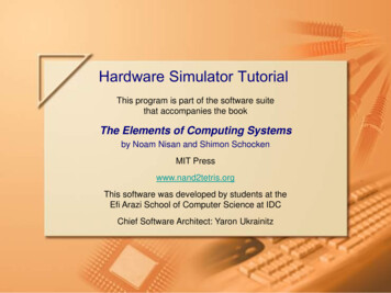
Another purpose of this article is to compare and contrast “early” wavelet coding with “modern” wavelet coding. Image coding was one of the first applications of thenewly discovered wavelet theory. The reason for this wasthat wavelet analysis was very similar to the well-established subband analysis, which meant that the techniquesof subband coding could be directly applied to waveletcoding. Modern wavelet coders use techniques which aresignificantly different from the techniques of subbandcoding and are based on ideas originating with EZW.This article will compare the techniques of the modernwavelet coders to the subband coding techniques so thatthe reader can appreciate how different modern waveletcoding is from early wavelet coding.The remainder of the article proceeds as follows. Thefollowing section discusses basic properties of the wavelettransform which are pertinent to image compression.The material in this section builds on the background material in generic transform coding given in [6] (furtherbackground in data compression can be found in[7]-[10]). This section shows that boundary effects motivate the use of biorthogonal wavelets, and introduces thesymmetric wavelet transform. The next section discussesthe subband coding or “early” wavelet coding methodfollowed by an explanation of the EZW coding algorithm. The last section describes other modern waveletcoders that extend the ideas found in the EZW algorithmand summarizes the article. 2. Original image used for demonstrating the 2-D wavelettransform.Wavelet BackgroundThis section describes some of the properties of the discrete wavelet transform that are pertinent to image compression. The discussion here shows why currentcompression systems use biorthogonal instead of orthogonal wavelets and shows why some biorthogonalwavelets are better choices than others. In addition, thissection discusses a particular form of the discrete wavelettransform, the symmetric wavelet transform, which hasbeen specifically designed to handle boundary effects.Only those aspects of wavelet analysis which are important for understanding lossy image compression are described here. A full introduction to wavelets is beyond thescope here but can be found elsewhere [11]-[18].The generic form for a one-dimensional (1-D) wavelettransform is shown in Fig. 1. Here a signal is passedthrough a lowpass and highpass filter, h and g, respectively, then down sampled by a factor of two, 0(n)dK1(n) 1. A K-level, 1-D wavelet decomposition. The coefficient notation dij ( n ) refers to the jth frequency band (0 for low and 1forhigh) of the ith level of the decomposition.SEPTEMBER 2001 3. A one-level (K 1), 2-D wavelet transform using the symmetric wavelet transform with the 9/7 Daubechies coefficients (thehigh-frequency bands have been enhanced to show detail).one level of transform. Multiple levels or “scales” of thewavelet transform are made by repeating the filteringand decimation process on the lowpass branch outputsonly. The process is typically carried out for a finite number of levels K, and the resulting coefficients,d i1 (n), i {1, , K } and d K 0 (n), and are called wavelet coefficients. When it is not necessary to know scale orfrequency information, the entire set of wavelet coefficients is referred to as { w(n)}. This article uses only themaximally decimated form of the wavelet transform,where the downsampling factor in the decompositionand upsampling factor in the reconstruction equals thenumber of filters at each level (namely two).The 1-D wavelet transform can be extended to atwo-dimensional (2-D) wavelet transform using separable wavelet filters [7], [19]. With separable filters the 2-Dtransform can be computed by applying a 1-D transformto all the rows of the input, and then repeating on all ofthe columns. Using the original image in Fig. 2, Fig. 3IEEE SIGNAL PROCESSING MAGAZINE23
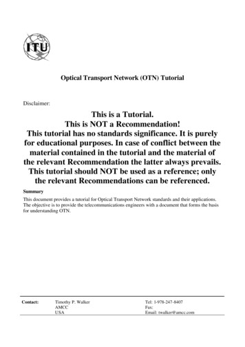
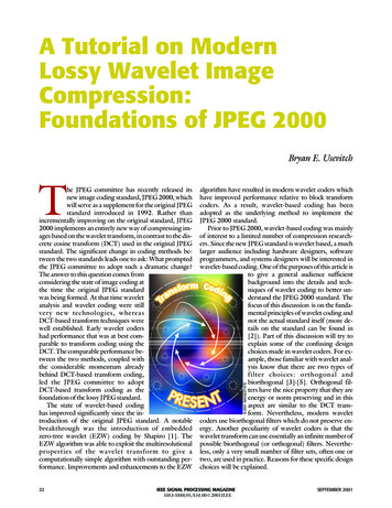
shows an example of a one-level (K 1), 2-D wavelettransform, with corresponding notation given in Fig. 4.The example is repeated for a three-level (K 3) waveletexpansion in Figs. 5 and 6. In all of the discussion K represents the highest level of the decomposition of thewavelet transform. The focus of this article is on 2-Dtransforms. However, since the 2-D transform is readilyobtained from separable extension of the 1-D transformand to simplify discussion, the remainder of this sectionillustrates concepts using only the 1-D transform.The original wavelet transforms was implemented using orthogonal wavelets, which are wavelet filters thatsatisfy orthogonality constraints h(n 2 i)h(n 2 j) δ(i j)n g(n 2 i) g(n 2 j) δ(i j)n h(n 2 i) g(n 2 j) 0.nLL1HL1LH1With orthogonal filters, the wavelet transform can beviewed as projecting the input signal onto a set of orthogonal basis functions. If the filters are also normalized,as they are in (1), the resulting wavelet transform is energy preserving. For an input signal x(n) of length N, thisenergy conservation property, which is analogous to theParseval property in Fourier analysis, can be writtenHH1N 1 4. The subband labeling scheme for a one-level, 2-D wavelettransform. 5. A three-level (K 3), 2-D wavelet transform using the symmetric wavelet transform with the 9/7 Daubechies coefficients(the high-frequency bands have been enhanced to show detail).LL3 HL3LH3 HH3LH2HL2HL1HH2LH1HH1 6. The subband labeling scheme for a three-level, 2-D wavelettransform.24(1) n 0L 1x 2 (n) w 2 (l).l 0(2)The energy conservation property is convenient for coding system design since the mean squared distortion introduced by quantizing the transformed coefficientsequals the mean squared distortion in the reconstructedsignal. Thus the energy conservation property simplifiesdesigning the coder since the quantizer design can be carried out completely in the transform domain.The standard orthogonal wavelet transform has someshortcomings that make it less than ideal for use in a coding system. One shortcoming is highlighted in (2), whereit is shown that the total number of input coefficients, N,does not equal the total number of wavelet coefficients, L,using the maximally decimated wavelet transform. Ingeneral L is greater than N and the wavelet transform results in “coefficient expansion.” This expansion is illustrated with a simple example. Consider a length N (even)input and length M (even) wavelet filters. The outputs ofthe filters h and g will be length N M 1, and the outputs of the decimators will be length ( N M) / 2. Thus,the N original input samples result in a total of N Mwavelet coefficients after one level of transform. Morelevels of wavelet analysis only makes the problem worse,since more levels result in more than N M samples.Figs. 7 and 8 illustrate the coefficient expansion problemfor a length 8 input and length 4 wavelet filters, and showthat the wavelet transform outputs 8 4 12 coefficientsafter one level of transform.Coefficient expansion is a problem for coding systemswhere the aim is to reduce, not increase, the amount of information to be coded. One simple way to eliminate coefficient expansion is to use circular convolution, ratherthan linear convolution, on the finite length input x(n).While solving the coefficient expansion problem, circularconvolution leads to the introduction of artifacts. Con-IEEE SIGNAL PROCESSING MAGAZINESEPTEMBER 2001
10.80.60.40.20 1013265487 7. Length 8 example input sequence.sider the example input signal of Fig. 7, which when periodically extended as shown in Fig. 9 has a large discontinuity ( x( N 1) x(0) ). Circular convolution of theinput results in large wavelet coefficients in the highpassband at the location of the discontinuity as shown in Fig.10. These large wavelet coefficients due to border discontinuities are undesirable because: They require more bits to code so that the reconstructed signal accurately represents the input; They do not represent any information present in theoriginal signal, but rather are an artifact of the methodused to perform the transform.Bits used to code these artificially introduced artifactscould be better used to code the original data.The border or edge artifacts can be eliminated by performing a symmetric periodic extension of the input inplace of a periodic extension (see Fig. 11). This symmetLow FrequencyLow Frequency1.51.5110.50.500 0.5 10132654 0.5 101.5110.50.5000132654 8. The d10( n ) and d11( n ) outputs of the wavelet transform forthe input given in Fig. 7, using the length 4 Daubechies orthogonal filters. Note that the number of output coefficients after one level of analysis is 12, illustrating the coefficientexpansion problem. 0.510.80.80.60.60.40.40.20.2 20246 9. The periodic extension of the input in Fig. 7.SEPTEMBER 200134810 101234 10. The d10( n ) and d11( n ) outputs of the wavelet transform ofthe periodically extended input of Fig. 9. Note that the largediscontinuity at the boundaries of the input result in largehigh-frequency coefficients in the wavelet output.10 42High FrequencyHigh Frequency1.5 0.5 110051015 11. Symmetric periodic extension of the original input shown inFig. 7.IEEE SIGNAL PROCESSING MAGAZINE25
1.41.210.80.60.40.20051015 12. The output resulting from filtering the symmetric periodicsignal of Fig. 11 with the length 4 Daubechies lowpass filter.Since the filter is not symmetric, the filtered output no longerhas symmetry.ric extension guarantees continuity across replicas of theinput and eliminates the large wavelet coefficients causedby border discontinuities. Note that symmetric extensiondoubles the number of input samples. This is not a problem initially since half the samples are redundant becauseof symmetry. However, when the input is filtered anddecimated, it results in outputs that are not necessarilysymmetric periodic (see Fig. 12). As a result, half the coefficients cannot be eliminated by symmetry, and there isa doubling of the number of coefficients required to represent the input. Thus this case is even worse than the linear convolution case where the number of coefficientsonly increased by the filter length M. Fortunately, symmetry can be preserved across scales of the wavelet transform by imposing an additional constraint on the waveletfilters h and g: they must be either symmetric orantisymmetric (also known as linear phase in signal processing terminology). For this special case, periodic symmetric inputs give periodic symmetric outputs and theresult is no coefficient expansion [20], [15].The use of symmetric extensions and linear phasewavelet filters would seem to solve the problem of bordereffects in the wavelet transform. However, there is stillone technical difficulty to overcome, which is illustratedby the following:Fact: For real valued, compactly supported orthogonalwavelets, there is only one set of linear phase filters, andthat set is the trivial Haar filters, h (1,1), g (1, 1) [3].The lack of linear phase filters in orthogonal waveletsled to research in extending wavelet analysis to more general forms, which would allow for linear phase filters. Theresearch resulted in a more general form of waveletsknown as “biorthogonal wavelets” [4], [5]. As the nameimplies, biorthogonal wavelets have some orthogonalityrelationships between their filters. But biorthogonalwavelets differ from orthogonal in that the forward wavelet transform is equivalent to projecting the input signal26on to nonorthogonal basis functions. The orthogonal andbiorthogonal wavelets transforms are analogous to orthogonal and nonsingular matrix transforms, respectively. Both the orthogonal and nonsingular matrixtransforms are invertible, but only the orthogonal matrixtransform is energy preserving. The main advantage inusing the biorthogonal wavelet transform is that it permits the use of a much broader class of filters, and thisclass includes includes symmetric filters.When the wavelet transform uses linear phase filters, itgives symmetric outputs when presented with symmetricinputs. This particular form of the wavelet transform (linear filters with symmetric inputs and outputs) is called thesymmetric wavelet transform (SWT). The SWT solvesthe problems of coefficient expansion and border discontinuities and its use has been shown to improve the performance of image coding applications [21], [20].Efficient practical implementation of the SWT involvesmany tricky details due to the lengths of the input and filters (even or odd) and decimation of the symmetric extensions. These details are fully explained in [15] and[22]. Those desiring to implement the SWT will also findthe paper by Vetterli and Herley [5] helpful since it characterizes the complete class of linear phase filters whichcan be obtained under the biorthogonal filter constraints.In summary, the biorthogonal wavelet transform hasthe advantage that it can use linear phase filters, but thedisadvantage that it is not energy preserving. The fact thatbiorthogonal wavelets are not energy preserving does notturn out to be a big problem, since there are linear phasebiorthogonal filter coefficients which are “close” to beingorthogonal. One example of such a wavelet filter set is the9/7 filter given in Table 1. This filter set can be pluggedinto the orthogonality constraints of (1) to show thatthey are nearly orthogonal. Another way of showing theapproximate orthogonality of these filters is to considerthe weighting introduced by nonorthogonality [23],Table 1. Two Sets of Linear Phase,Biorthogonal Wavelet Filter Coefficients.9/7 FilterCoefficientsh0g05/3 .0606600.70710700.3774020.4180920.3535530.353553 1, 1 0.110624 0.040689 0.176777 2, 2 0.023849 0.064539 3, 30.037828 4, 4The 9/7 coefficients have the nice property that, althoughthey are biorthogonal, they are very close to beingorthogonal as shown in Table 2.IEEE SIGNAL PROCESSING MAGAZINESEPTEMBER 2001
[24]. Table 2 shows the weighting from subband to reconstructed output caused by the reconstruction waveletfilters for some example filter sets (the relation betweensubband variances σ 2ij , weights w ij , and output varianceσ 2 is given byσ2 K1 21σw ij σ 2i1 , L0Ki2i 1 2where the 1 / 2 i factors arise because of subband size).These weights can be computed by taking the l 2 norm ofthe single equivalent filter which takes the subband coefficients directly to the reconstructed output. Note that fororthogonal filters the weights are all one (indicating thatenergy is preserved between transform coefficients andreconstructed output). Also note that the 9/7 filter set hasweights that deviate by only a few percent from one,showing that the filter set is reasonably close to being orthogonal. Besides being nearly orthogonal, or perhapsbecause of being nearly orthogonal, the 9/7 set has beenshown experimentally to give very good compressionperformance and has been used extensively in image compression applications [25], [26].Using biorthogonal wavelets in conjunction with symmetric extensions is not the only solution to the border effects problem. Orthogonal wavelets which employboundary filters [15] are another solution to this problem. So why not just use orthogonal wavelets with an alternate method? It turns out that given all things equal,such as orthogonal and biorthogonal wavelets using circular convolution, biorthogonal wavelets still give betterperformance than orthogonal wavelets [21].Table 2. The Implicit Weighting Introduced on theWavelet Coefficient Energy as It Is Transformed tothe Reconstructed 000w111.000001.040431.43750w 201.000001.030600.68750w 000001.075120.76074Note that the 9/7 biorthogonal filter set deviates by only afew percent from the orthogonal filter weighting.SEPTEMBER 2001Wavelet coding techniquesprovide a very strong basis forthe new JPEG 2000 codingstandard.Subband CodingThis section gives a brief overview of the subband codingmethod. Subband coding is a good example of a codingmethod which follows the generic transform codingmodel discussed in [6]. Subband coding is also used hereto illustrate “early” wavelet coding, since early waveletcoders and subband coders use identical coding techniques, with the only possible distinction between thetwo being the choice of filters. As a result, the terms “earlywavelet coding” and “subband coding” are used interchangeably here. Because early wavelet coding andsubband coding are essentially identical, the coders discussed in this section will serve as a point of referencewhen discussing modern wavelet coders. A main goal ofthis section is to point out some of the weaknesses ofsubband coding that are later addressed by modern wavelet coders.In subband coding, the transform block is implemented through filtering and decimating analogous tothe wavelet transform (see Fig. 1). For image data, the filtering and decimation is applied recursively on the LLiband to give an octave subband decomposition equivalent to those shown in Figs. 4 and 6. The main differencebetween subband and wavelet coding is the choice of filters to be used in the transform. The filters used in waveletcoding systems were typically designed to satisfy certainsmoothness constraints [3]. In contrast, subband filterswere designed to approximately satisfy the criteria ofnonoverlapping frequency responses. To explain thisnonoverlapping criteria, remember from [6] that the goalof the transform section of a coding system is todecorrelate coefficients. A well-known theorem statesthat random processes which have nonoverlapping frequency bands are uncorrelated [27]. It is this propertythat the subband filtering uses to try to achievedecorrelation. Adding the additional constraint that thetransform be (nearly) lossless, subband filters are designed to be approximations to ideal frequency selectivefilters [28], where the combined response from all the filters covers the entire spectral band. Total decorrelation isnot achieved since filters only approximate ideal filters.The output of the transform stage for a K level octavedecomposition on image data is 3 K 1 separate subbandsof coefficients. By the design of the subband filters, thecoefficients in each subband are (approximately)uncorrelated from coefficients in other subbands. As a result, the coefficients in each subband can be quantized independently of coefficients in other subbands with noIEEE SIGNAL PROCESSING MAGAZINE27
The biorthogonal wavelettransform has the advantage thatit can use linear phase filters, butthe disadvantage that it is notenergy preserving.significant loss in performance. The variance of the coefficients in each of the subbands is typically different, similarto the different variances of the DCT coefficients in theoriginal JPEG standard, and thus each subband requires adifferent amount of bit resources to obtain best codingperformance. The result is that each subband will have adifferent quantizer, with each quantizer having its ownseparate rate (bits/sample). The only issue to be resolvedis that of bit allocation, or the number of bits to be assigned to each individual subband to give best performance.To illustrate the process, we present an example solution to the bit allocation problem for the case of uniformscalar quantization in each of the subbands. To keep thediscussion simple, assume that the subband decomposition is only one level, resulting in the four subbands LL1 ,HL1 , LH 1 and HH 1 , which are indexed as subbands 1through 4 respectively. The goal is to assign each subbanda bit rate, denoted as R k bits/coefficient, such that 1) An overall bit rateR 1 4 R4 k 1 k(3)is satisfied and 2) The reconstruction distortion is minimized.Since uniform scalar quantization is used, the distortionor error energy introduced by the quantizer in eachsubband can be modeled by [8], [ 9]σ 2r k α k 2 2 R k σ 2y k ,(4)where σ 2y k is the variance of coefficients in each subband,R k is the subband bit rate, andα k is a parameter which depends on the probability distribution in the subbands(Gaussian or Laplacian or uniform, etc.). Equation (4)makes intuitive sense since the more bits/sample allocatedto the subband (R k ), the lower the resulting distortionfrom that subband. Using (4), the total reconstruction error of the wavelet coefficients, assuming the same α k ineach subband, is4σ 2r α 2 2 R k σ 2y k .k 1(5)Equations (3) and (5) can be combined to form a constrained minimization problem which can be solved us28ing Lagrange multipliers [29], where the Lagrangian tobe minimized is4 1 4J α 2 2 R k σ 2y k λ R R k . 4 k 1k 1Minimization of this function results in the best bit allocation of [8], [9]1R k R log 22σ 2yk M(σ 2yk )1 / Mk 1.(6)Equation (6) is not valid in all cases, for example when itresult in R k s that are negative, but methods have been derived to handle these technicalities [10]. Using the optimal bit rates, the coefficients in each of the subbands areindividually quantized with their respective quantizersand then entropy coded to give the final coded representation.Some of the shortcomings of subband coding can nowbe pointed out by considering the previous discussion.The first shortcoming is that the quantizer model of (4)used to derive the optimal bit allocation is only valid for“high bit rates” of approximately 1 bit/sample or more.The approximation worsens as the bit rates are reducedbelow 1 bit/sample and the optimal bit allocation of (6) isno longer valid. Consequently, the subband codingmethod is not able to determine optimal coding systemsfor low bit rate applications.A second problem with subband coding involves thecoding of an image at multiple target bit rates. As an example, consider the case of coding an image to give the resulting bit rates of 0.5 and 1.0 bits/sample. Rather thansolving two coding problems, it would be nice to code theimage at one bit rate, say 0.5 bit/sample, and then use thisinformation to simplify the coding at the 1.0 bit/samplerate. The idea of reusing information to simplify the derivation of extended results is a common theme in modernsignal processing, with recursive least squares and latticefilters being common examples. Unfortunately, forsubband coding, the optimal bit allocation changes as theoverall bit rate changes, which requires that the codingprocess be repeated entirely for each new target bit ratedesired.Finally, with subband coding it is difficult to code aninput to give an exact target bit rate (or predefined outputsize). This is due to the entropy coding of the quantizeroutputs and the approximation inherent in the quantizermodel of (4). One solution to this problem, if the codedoutput is too large, is to truncate the coded data. Unfortunately, truncation removes entire subband coefficients,which can result in visual artifacts (you can see in the image where the data was truncated). If the coded outputdata is too small, more overall bits can be allocated andthe subband coding procedure repeated. The disadvantage to this is that the coding procedure must be repeated,IEEE SIGNAL PROCESSING MAGAZINESEPTEMBER 2001
again with no guarantee that the target output size will beachieved.To finish this section some examples of the subbandcoding method are mentioned. This list includes earlywork in subband coding done by Vetterli [30] andWoods and O’Neil [31]. Example coders using waveletanalysis filters include those using scalar quantization[19], [25] and vector quantization [25], [32] of thesubband coefficients. Another very good example of anearly wavelet coder is the wavelet scalar quantization standard (WSQ), which has been adopted by the Federal Bureau of Investigation as the method for compressing theirentire fingerprint database [33], [22], [34].The original or “heritage” wavelet coders were based onthe same basic ideas found in subband coding. The era ofmodern lossy wavelet coding began in 1993 when JerryShapiro introduced EZW coding [1]. EZW coding exploited the multiresolution nature of the wavelet decomposition to give a completely new way of doing imagecoding. The resulting algorithm had improved performance at low bit rates relative to the existing JPEG standard, as well as having other nice features such as acompletely embedded bit representation. EZW markedthe beginning of modern wavelet coding since improvedwavelet coders proposed subsequent to EZW are basedon fundamental concepts from EZW coding. This section fully describes the EZW algorithm by first discussing the statistical properties of wavelet coefficients resulting from image data. Next, the two key concepts ofEZW, namely significance map coding using zero-treesand successive approximation quantization, are described. Finally, the EZW algorithm along with an illustrative example are given.One of the beneficial properties of the wavelet transform, relative to data compression, is that it tends to compact the energy of the input into a relatively small numberof wavelet coefficients (this property can be shown to beequivalent to reducing the correlation amongst waveletcoefficients) [35]. For example, in naturally occurringimages, much of the energy in the wavelet transform isconcentrated into the LL K band. In addition, the energyin the high frequency bands (HLi , LH i , HH i ) is alsoconcentrated into a relatively small number of coefficients. This energy compaction property can be observedin the probability distribution of wavelet coefficients inthe high frequency subbands, which has been shown inprevious studies to have a Laplacian-like density2)β,(7)whereσ 2 is the variance andβ is the rolloff of the distribution [19], [31]. A sample density is shown in Fig. 13which shows that the density is symmetric, peaked atzero, and has relatively long tails. The high peak aroundSEPTEMBER 20010.30.250.20.150.10.050 10Embedded Zero-Tree Wavelet Codingf ( x) Ae( x / σ0.35 8 6 4 20246810 13. A plot of the probability density of (7) with σ 2 15. , β 1,and A 1/ 3. 14. A two-level, 2-D wavelet transform illustrating the propagation of significant coefficients across frequency bands. Notethat the significant coefficients occur at the same relative spatial location in each of the subbands of the same frequencyorientation.zero means that most coefficients in a frequency subbandhave small magnitudes and thus have small energy. Also,the long ta
DCT-based transform techniques were well established. Early wavelet coders had performance that was at best com-parable to transform coding using the DCT.Thecomparableperformancebe-tween the two methods, coupled with the considerable momentum already behind DCT-based transform coding, led the JPEG committee to adopt DCT-based transform coding .