Transcription
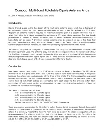
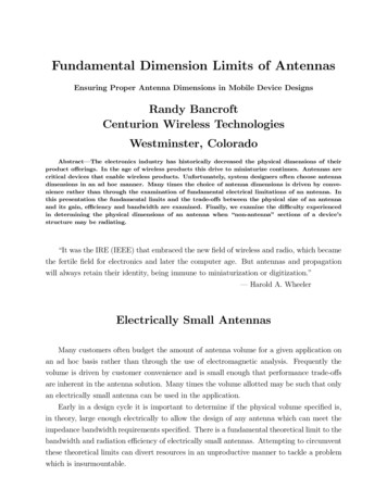
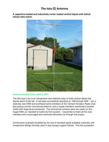
Journa l of Research of the National Bureau of Standards- D. Radio PropagationVol. 64D, No.1, January- Fe bruary 1960Effect of Antenna Size on Gain, Bandwidth, andEfficiencylRoger F. Harrington 2(June 29, 1959)A theore tical ana lysis is m a d e of the effect of antenna s ize on para meters such as gain,bandwidth, and efficiency . Both near- zone and far-zon e direct ive gains are considered . Itis found that t he maximum gain ob tainable from a broa d-band a ntenn a is approxima telyequal t o that of the uniformly illumina ted ap er t ure. If higher gain is desired , the antennamus t necessarily be a narrow-band d evice. In fa ct, th e input impedance becomes frequ encysensitive so r apidly that, for large a nte nnas, no significan t increase in gain over tha t of theuniformly illuminated aper t ure is possible. Also, if t he a ntenn a is loss y, t he efficiency fallsrapidly as the gain is increased over that of the uniformly illumin a t ed aperture.1. IntroductionAs a practical ma t ter , the maximum direc tive gain (direc tivity) of an antenn a dependsupon its physical size compared to wavelength. The uniformly illuminated aperture type ofantenna has been found to give a higher gain in practice than other antennas, at least for largeapertures. However, the uniformly illuminated ap er ture docs not represent a theoretical limitto the gain. Higher direc tive gains appear to b e possible, but analyses of proj ec ted "supergain"antennas r eveal extreme frequency sensitivity at b es t, excessive losses at worst. This papergives a theoretical trea tment to the general problem , from which quantitative bounds to ant enna performance may b e ob tained . The analysis considers both the ncar-zone and the farzone gain of antennas.L et the spherical coordinate system be defined as in figure 1. The directive gain as a function of distance from an antenna is defin ed as the r atio of the maximum d ensity of outwarddirec ted power flux to the average density. In equation form this isG({3r)47rT 2R e(S r)maxRe (P )(1)1where S, is the radial component of the complex P oynting vec tor at a distanceoutward-direc ted complex power over a sphere of radius r.T,and P is thezrFI GU R EI,xyII'JI2This work b as been snpported by Oenera l Elcctric Company, subcontract N o. 500-7119D epartment of Electrical En gineering, Syracuse University. Syracuse, N.Y.11.The spherical coordinate system.
The field external to a sphere containing all sources can be expanded in terms of sphericalwave functions. Th(\ general form is [1] 31E - v X (r-J;) -.JWEAv X v X(r-J;)(2)1H v X(r-J;) -. V X v X(r-J;)AJWJ1.where r is the radius vector from the origin and-J; m,nA mnM,2) ({3r)P ,::(cos 0) cos (m 4 amn)(3) B mnM,2 )({3r)P'::(cos 0) cos (m4 a mn )1n.nwhere A mn, B mn, a mn , and amn are coefficients which do not depend on r, 0, or 4 , and {3 27r/ wavelength. From the above formulas for the field can be calculated the power over a sphere ofradius r'" n(n l) (n m)! (! IA 12 IB 12)Re (p) 47r(32 Em(2n 1) (n-m) ! 1/mn1/ mnwhere Em is Neumann's number andin the 0 0 direction is1/ 1207r.(4)The radial component of the power flux densitywhereEz n( tl)[A ln sin alnFn({3r) - j 1/Bln cosalnF (f3r) ]Ey n( t l)[ Aln cos al nF n({3r) hB ln sinalnF ({3r) ]Hx n( :l)nr[ - BI n sin al nFn({3r) i A ln cos alnF ({3r)J1/ (6)andThe coordinate axes are to be oriented so the maximum radiation is in the 0 0 direction. Thenthe STof (5) is the (S r)max of (1).Note that a mn and amn do not enter into the formula for power, (4). Also, from the symmetryof (5) and (6) it is evident that the density of power flux in the 0 0 direction is independent ofa ln and al n. Hence, they may be chosen in any convenient manner. In particular, let al n 7r/2, 1n 7r, which give a field linearly polarized in the x direction. With this choice, the gain (1)becomes(8)3Figures in brackets indicate th e literature references at the end of th is paper.2
wher e(9)Equation (8) is a general formula for directive gain .2 . Maximum Gain)If all orders of spherical wave functions are permitted there is no limit to the gain of anantenna. However, a definite limit to the gain exists if wave functions are restricted to ordersn:5:N. Only the AI" and B In contribute to the numerator of (8), so the gain can b e increasedby settingA mn Bmn O(10)Furthermore, the gain formula is symmetrical in a n and bn so the maximum gain will exist underthe condition(11)Equation (8) has110Wb een redu ced toG Re[( anUn) ( anu n)*]n 1n 114 [a,,[2 2n 1N(12)where(13)The numerator of (12) can now b e in creased without changin g the denominator by seLLing(14)in whi ch case (12) b ecom e(15)Finally, the [ani are adjusLed for maXImum gain by r equiring oGjo [ai[ Ofor all ai. The result isNG(f3r) max t (2n 1 ) [u n (f3r) [ (16)n 1 Iwhich is the maximum directive gain obtainable using wave fun ctions of order nmaximization procedure also r es ulLs in the r elatlOl1shipI :I(2n 1) [u ,,[(2i 1) [u i[:5: N. The(17)From (13 ) it follows that[u ,,(f3r) [2 W:'(f3r) [2 W n(f3r) [2 2.(18)As f3r-'HX , [un [2--i 4, so in the far zone (16) reduces toNG( CD )max (2n 1 ) N2 2Nn 1whi ch ha b een previously published [1].3l(19)
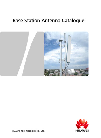
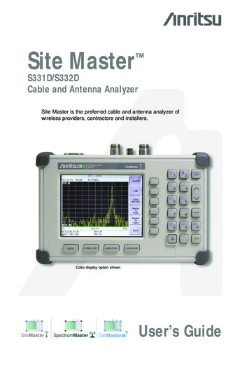
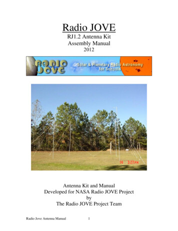
The lu,,12 functions, which enter into (16) and also into later formulas, are shown in figure 2.The maximum directive gain for various {3r and various N has been calculated. Figure 3 showsthe ratio of the near-zone gain to the far-zone gain for several N. Note that the maximumnear-zone gain is essentially the same as the maximum far-zone gain unless (3r N. Keep inmind that the excitation of the antenna is changed as (3r is varied so that it is always adjustedfor maximum gain at the given radius. One can think of the antenna as being focused at thedistance r.I L- o14FI GURE2.The functions1511Ii18IS202122lu n (Br)12.3. Ratio of the maximum gain at a distance r to themaximum gain at infinity, using wave functions of ordern::;N.G( r)FIGUREcr-;;J r4(
3 . Quality FactorSo far the antenna structure has not been mentioned. An ideal loss-free antenna ofradius R is defined as one having no energy storage r R, which is the same as Chu's definition [2]. The quality factor('1Q-l2w WelectRe(P)2w Wm agR e(P)(20)for this ideal antenna must be less t han or equal to that for any other loss-free ant.enna fittinginto the sphere r R, since any field rR can only add to the energy storage. In (20) theenergies Ware those obtained by subtracting the radiation field from the total field. If the Qof an antenna is high, it can be interpreted as the reciprocal of the fractional bandwidth ofthe input impedance. If the Q is low the antenna has broadband potentialities.Because of the orthogonality of the spherical wave functions , the total electric energy,magnetic energy, and power radiated is the sum of the corresponding quantities associatedwith each mode. The Q can therefore be found by treating the field of each spherical waveas if it existed on a "spherical waveguide" isolated from all other waves [2,3]. The energyand power formulas of tran mission line theory apply Lo each spherical waveguide if a vol tagc,current, and characteristic im.pedance are defined for each TEmn wave as jTIt A",n(3Inll47rn(n 1) (n m) ; jF ((3r)7) Em(2n 1)(n- m).(21)47r11 (n 1) (n m) ! Fn((3r)(2n 1) (n-m)!(22)and for each Tlv!mn wave as7)EmZi:. 1 jF ((3r) iFn((3r).An antenna adjusted for maximum gain has equal excitation of TE and TM waves. It istherefore convenient to define modal quality factors2w W electmnn Re(P mn)Q2w WmagmnRe(Pmn) '(23)where the TVmn and P mn are the sum of the energies and powers of both the TEmn and Tlv!mnwaves. Note that the Qn's are independent of m since the characteristic impedances, (21) and(22), are independent of m. These are the same Qn's defined by Chu for circularly polarizedomnidirectional antennas [2] . Abstracting from Chu's work, one hasQn((3R) !lFn((3R ) 1 2f3RX (f3R)5(24)
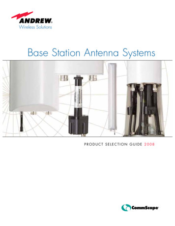
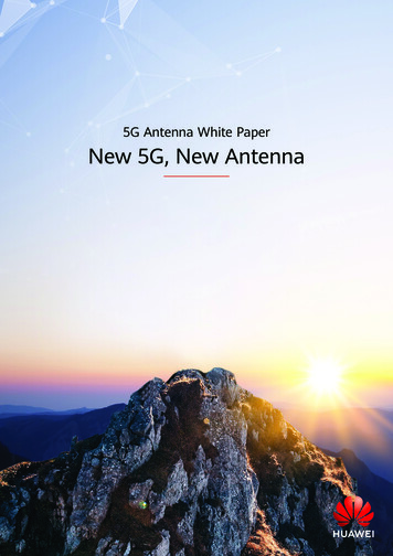
where R is the radius of the spherical antenna andX n (/3R) Im [Z f[({3R) l.(25)These Qn are approximately one-half those calculated by Chu for linearly polarized omnidirectional antennas. A plot of some Qn is given in figure 4.FI GU RE4.1Il 0dai quality jactors for u'ave functions of ordel 11 .The Q of an ant.enna having equal exc itation of TE and T.M waves is given byQm,n.L:; R e(P ,nn)(26)m,'T!since it is merely necessary to add the energies and powers of the individu al waves. For maxi mum gain all P mn O except P In, n:::; K. It follows from (9), (11 ) , (2 1), and (22 ) that(27)so the formuJa for Q b ecom es(28)
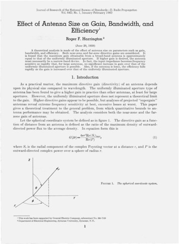
Finally, from (17) one has(29)as the quality factor for an ideal antenna of radius R, adjusted for maximum gain at a radius r,using wave functions of order n .5.N. For an antenna adjusted for maximum gain at infinityN (2n l )Qn({3R)Q- t n-,-- l c;-o;;;-:---c PH""fV2 2N(30)Figure 5 shows the Q of antennas focused at infinity for several N. (The dashed lines represent5. Q1wlity factors f or ideal loss-free antennasadjusted for maximum gain at infinity , using wavefuncti ons of order 11 :::; N (das hed lines sho w the e.Oectoj losses).FIGUREthe effect of antenna losses, considcrcd below.) CalculaLions for antcnnas focuscd at othcr l'show that the Q is substantially independent of the radius of fo cus. No appreciable changc inQ occurs until l ' is almost equal to R, that is, the field poin t is almost at the antenna surface.When r R , the Q of the antenna is close to the Qn of the highest order wave prcsent. When{3R N, all Qn are of the order of unity or less, and the quality factor isQ .5. 1(31)In this case the antenna is potentially broad band.4 . Effect on Antenna LossesTo obtain quantitative results for the effect of conduction losses on antenna performancean idealized model is again postulated. Intuitively one 'would expect the losses on a metalantenna to be smaller the more effectively the sphere is utilized. Therefore, for the ideal lossyantenna is postulated a spherical conductor of radius R excited by the magnetic sources(32)
on its surface. So long as the spher e is a good conductor the source of (32) will generate thedesired field [4] . If the conductivity of the sphere is poor, (32) can be modified to allow fora field internal to the conductor.The above postulated ideal lossy antenna is particularly simple to analyze because thewave functions are orthogonal over its surface. The effect of the spherical conductor is thatof a discontinuity in the characteristic impedance of each "spherical waveguide" at the radius R.The effect of t he source M is that of a voltage source in series with each waveguide at theradius R. The waveguides are matched in each direction, so the equivalent circuit for eachmode is a voltage source in series with the two characteristic impedances, T R and T R. ForT R the characteristic impedances for the various modes areZ;"1f. [Fn(kJ')/jF (kJ') ] * "'" 1/c/1/1/'(33)where k and 1/c are the wave number and intrinsic impedance in the conductor,(34)The characteristic impedance T R is extremely small for good conductors, so T1mn ", ,O, l' R.The current 1mn must be continuous at T R. Hence for any mode the ratio of power dissipated to power radiated is given by11mnl 2 Re(Zm-n)11",,,1 2 Re (Z,';n)where the sup erscripts and - refer to l' R and l' R, respectively.are defined for the case of equal TEmn and TMmn excitation as(35)Dissipation factors Dn(36)The Dn are independent of m because the Zmn are indep endent of m.one hasUsing (21) and (22)Dn( R) R 1/c) [JF ( R) 12 JFn( R) 12](37) R 1/c) [Jun( R)J2-2]where the lu n l2 are plotted in figure 1. Note that the D n are essentially proportional to theJU n l 2 when R n.The dissipation factor for an antenna having equal excitation of TE and Tkl waves isdefined as(38)m,n8
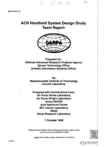
'where P mn is P;;' P;;' f. The second equality of (38) follows from the orthogonality propertyof the modes. For maximum gain all Pmn O except P in, n:5.N, which are given by (27).U ing this and (17) one hasN (2n 1 )ju n ({31') j2D n ((3R)D n.:. --,l'--- N ----- (2n 1 )(39)jUn ((31') j2n las the dissipation factor for an ideal lossy antenna of radius R, adjusted for maximum directivegain at a radius 1', using wave functions of order n:5.N. For an antenna adjusted for maximumgain at infinityND- - t (2n 1)D n ((3R)n l :-;-::-c;-;--(3H .,N2 2N(40)Figure 6 shows the dissipation factor of antennas focused at infinity for several N. Oalculationsfor antennas fo cused at other values of r show that D is essentially independent of the radius100000 o6. Dissi pation factors (D ) for ideal lossy antennasadjusted for maximum gain at infinity, u sing wave functionsof order n: :;N.FIGURERe ( c ) 1000of focus, except when r R. When 1' R, the D of the antenna is approximately the D n of thehighest order wave present. If (3R N, all D n are approximately Re(T]c)/T] , and the dissipation factor is(41)and the antenna has very small loss.The efficiency of the antenna is% efficiency524214- 59- -2100P radPrad PdlsB9(42)
The antenna remains reasonably efficient until D is of the order of unity.also changes the effective Q of the antenna, defined asThe dissipation(43)wmag W electBecause of the orthogonality of energy and power,responding quantities for each mode, that is,P rad Pd;'sis simply the sum of the cor-P rad P dI SS (P mn) rad (1 Dn) .(44)m,nThus, for an antenna containing only the 1, n modes, n5:.N, one has instead of (28)(45)Finally, if the antenna is adjusted for maximum directive gain, the an are given by (17 ) and(46)N (2n 1) [u n({jr)!2[l D n(f1R)]n lIf the antenna is adjusted for maximum gain at infinity this becomesNQell (2n 1) Qn(fjR)n l - N.-- - - - - - - -6r-7 00 (2n 1) [l Dn(fjR)](47)n lThe dashed lines in figure 5 show the effective Q for various N assuming Re('7c)/2'7 10-4,which corresponds to good conductors in the vicinity of 10,000 Me. Further calculationsshow that the effective Q is essentially independent of the radius of focus, just as in the lossfree case. For large antennas, the maximum effective Q is of the order of that for a goodspherical resonator constructed of the same metal.'iVhile the directive gain of an antenna is unaffected by dissipation (assuming that thecurrent distribution is unchanged), the overall gaing(fjr)41lf2Re (Sr)max(48)Prad Pd'BBis affected. This is the gain usually of primary interest for antenna evaluation. One canquite simply go back and maximize g, since the P dlBS of each mode is related to the Prad of eachmode by (35 ). The only difference in the equations for G and those for g is that the factor1/ (2n 1) is replaced by (I D n)/ (2n 1). Hence, (16) becomes 41N(2n 1)2gmax 4 l D n(fjR) [Un(fjr) [(49)I This procedure is slightly in error since dissipation factors for TEand TMmodes alone are not quite equal. T he correction is small, however, until the dissipation factors become quite large.10
and th e wave amplitudes, related previously by (17 ), are related bylanl (l D t ) (2n l )lun llatl (1 D n) (2i 1) Iuil(50)N ote that the maximum gain is now a function of R (antenna size) as well as r (field point ).If the antenna is focused at infinity (49 ) r educes to(51 )So long as DN l the overall gain g is substantially equal to the directive gain G. If DN 1the maximum gain dep ends upon the surface r esistance of the metal, R e(17c)' However, thelun l2 functions, which enter into D n according to (37), rise very rapidly . For good conductorsthe "cut-off" of the summation of (46 ) occurs at approximately the sam e value of n as thatfor which the Qn level ofl'.When the overall gain instcad of the directive gain is maximized it affects the dissipationand quality factors. The di ssipation factor becomesN (2n 1) /Un({31') 12D ,,({3R)/ [l Dn({3R)J2' l D -- '--N (2n l )/u n({3r)J2/ [l,, 1 D n({3R)J2(52)instead of (39). The principal differe nce between (39 ) ancl (52 ) is that in the latter case Dlevels off when the Dn b ecomes greater than unity. This can b e thought of as due to the nOIlutilization of modes which arc highly dissipative. The quality factor b ecomesN (2n n l1) IUn ({3r) 2 Q,, ({3R )/ [l D n({3R)F1(53)N (2n 1) IUn({3r) /2j[l D,,({3R»)n 1instead of (46 ) .A plot of (53 ) would again give curves similar to the da sh ed lines of figu re 5 .5 . DiscussionTo relate the a nalysis to practical a n tenna systems, define t he mditls 1i of an a ntennasystem to be the radiu s of the smallest sphere that can contain it. The Q of the id eal lossfree antenna must t hen be less than or equal to the Q of any other loss-free antenna of radiu sR, since fields r R can only add to energy storage. In other words, the Q of figure 5 is alower bound to the Q of an arbitrary loss-free antelwa of radius R. It would b e nice if on ecould also prove that the dissipation factor D of the ideal lossy antenna were 11 lower bound tothe D of an arbitrary antenna of th e same material and radius. The a uthor bas not bee n ableto prove this. However, it will be ass umed t hat t he D of t he ideal lossy ante nna is of the sameorder of magnitude as for other antennas of the same material and radius. Oalculations of t heD for some practical antennas support this assumption .It is evident from the foregoillg analysis that a marked change in the behavior of an antenna of radius R occurs when wave functions of order n {3R arc present in its field . In theloss-free case the Q is large. In addition to th is, in th e lossy case t he dissipation is large. Inboth cases the near-field is characteriz ed by extremely large field intensities. The normal gainof an antenna is defined to be the maximum gain obtainable using wave functions of ordern5:.N {3R . Hence, from (19), the normal gain of 3,n antenna of radius R isGnorm ({3R)2 2({3R)11(54)
in the radiation zone. Systems having larger gain than this are called supergain antennas.For large {3R the gain of a uniformly illuminated aperture of radius R is equal to the abovedefined normal gain [5]. Therefore, one cannot obtain a gain higher than that of the uniformlyilluminated aperture without resorting to a supergain antenna.It is evident from figure 3 that the maximum near-zone gain of an antenna using wavefunctions n N {3R is essentially the same as the maximum far-zone gain. Hence (54) alsodefines the normal near-zone gain for all practical purposes. A uniformly illuminated and"focused" aperture (phase adjusted so that all elements contribute in-phase at some distance r )has a near-zone gain approximately equal to the far-zone gain of the "unfocused" aperture(uniform phase). Thus, a near-zone gain greater than that obtainable from a focused uniformly illuminated aperture cannot be obtained without resorting to a supergain antenna.Having precisely defined the term "supergain," one can now consider the question of howmuch supergaining is possible. If a particular Q is chosen, the possible increase in gain overnormal gain can be readily calculated. For example, if Q 106 is taken, the decibel increase ingain over normal gain is as shown in figure 7. Note that for small R, substantial increases ingain can be achieved, but for large R the increase becomes insignificant. The curve of figure 7is relatively insensitive to the particular choice of Q, so long as it is high. This is evident fromthe rapid rise of the curves of figure 5. The choice Q 10 6 represents sort of an upper limit topractically significant Q's, since the bandwidth becomes absurdly narrow for higher Q's. Also,Q 10 6 represents the approximate upper limit for antennas constructed of metal, due todissipation.7. Maximum increase in gain over normal gainobtainable by su pergaining 1j a Q of 106 is allowed.FlO U Rl"O O -- IO-- 10 --l O-- 40 5 O --- '60 7 O ---8 O-- 90·It is evident from figure 5 that tIle amount of supergaining possible in large antennas isvery small. Hence, for practical purposes, the uniformly illuminated aperture gives optimumgain. For small antennas, however, a significant increase over normal gain is possible. Perhaps the most common example of a small supergain antenna is the short dipole. The problems of narrow bandwidth and high losses associated with this antenna have been thoroughlytreated, since it is one of the few antennas that can be used at very low frequencies.6. ReferencesR. F. Harrington, On the gain and beamwidth of directional antennas, IRE Trans. AP-6, 219 (1958) .L. J. Chu, Physical limitation s of omnidirectional antennas, J . Appl. Phys . 19, 1163 (1948).N. Marcuvitz, Waveguide handbook, pp. 96- lO0 (McGraw-Hill Book Co. , New York, N .Y ., 1951) .R. F. Harrington, Introduction to electromagnetic engineering, pp. 167- 177 (McGraw-Hill Book Co ., N ewYork, N.Y., 1958).[5] S. Silver, Microwave antenna theory and design, p . 177 (McGraw-Hill Book Co ., N ew York, N.Y., 1949) .[1][2][3][41(Paper 64Dl- 31 )BOU LDER, COLO.12
uniformly illuminated aperture is possible. Also, if the antenna is lossy, the efficiency falls rapidly as the gain is increased over that of the uniformly illuminated aperture. 1. Introduction As a practical matter, the maximum directive gain (directivity) of an anten