Transcription
Application NoteDesigning for Performance on Flash-Based FPGAsTable of ContentsAbstract . . . . . . . . . . . . . . . . . . . .Introduction . . . . . . . . . . . . . . . . . .Brief Introduction to Flash FPGA ArchitectureRoot Causes of Timing Issues . . . . . . . .Main Sources for Design Analysis . . . . . .Ingredients for Timing Optimizations . . . . .Conclusions—Forward Looking . . . . . . . .1.1.2.5.7.916AbstractRecently, the market has seen the birth of new FPGAs that embrace for the first time applications andsystems with very stringent timing and power requirements. Novice and experienced FPGA and ASICdesigners face similar problems when it comes to achieving timing closure in a very limited number ofiterations. This paper introduces the main ingredients for tackling this problem without penalties orfrustration. The basic ingredient is a good understanding of the FPGA architecture and its embeddedfeatures. The exploitation of these features is the key to coping with several hurdles. The secondingredient is a great analysis methodology of the bottlenecks that can be inherent to the design itself,caused by the tools or by the user settings. The third ingredient is the knowledge and understanding ofthe tools’ underlying techniques and potential optimizations and limitations. To make a sauce of thesemain ingredients—i.e., quickly converge and meet timing—this paper proposes a methodology using acombination of synthesis tools and Designer, the Microsemi physical design toolset.IntroductionFPGA designers often face daunting timing challenges. To reduce their frustration and to shrink theirdesign time and effort, this application note is intended to help users analyze their design, identify theroot causes associated with the timing issues, and finally cope with them.One other important goal is to help designers predict the outcome of their design decisions or toolssettings. This paper highlights when a particular user action may be efficient and what is the effect ofcombining several user actions. The document will also cover some of the cautions that need to beconsidered when dealing with some of the timing-critical situations. User actions described in thisdocument cover the following: RTL coding Synthesis options setting Place and route constraints and options settingThis document is organized in four sections. "Brief Introduction to Flash FPGA Architecture" on page 2 presents the salient architecturalfeatures of the Flash-based Microsemi FPGAs: IGLOO, Fusion, ProASIC 3, and ProASIC3L. "Root Causes of Timing Issues" on page 5 focuses on the main sources of timing challenges andways to identify them.June 2015 2015 Microsemi Corporation1
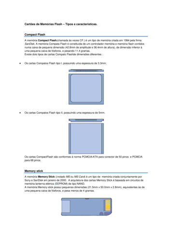
Designing for Performance on Flash-Based FPGAs "Main Sources for Design Analysis" on page 7 introduces various design techniques to cope witheach of these root causes of timing challenges. These techniques include RTL coding, synthesisflow setting, place-and-route, and physical and routing constraints. "Ingredients for Timing Optimizations" on page 9 focuses on inherent design congestionmanagement and provides various results.Brief Introduction to Flash FPGA ArchitectureThis section will only briefly cover some features in the IGLOO, Fusion, ProASIC3, and ProASIC3L FlashFPGA families. For full details, the reader can refer to the corresponding product handbooks.Basic CellThe basic cell, called VersaTile as depicted in Figure 1, is a LUT with three inputs that can indifferentlyimplement a three-input combinatorial gate or flip-flop with enable. This allows the implementation of anydesign with any combinatorial vs. register ratio. The nature of this tile makes it close to basic ASIC cellsin the sense of its fine granularity, thus allowing ASIC-like cell-based mappers to apply all theiroptimization potential.01YPin 1DataX30101F2YL01CLKX2CLR/EnableX1CLRXC*Legend:Via (hard connection)Figure 1 Logic Cell or Versatile Architecture2Switch (flash connection)Ground
Brief Introduction to Flash FPGA ArchitectureRoutingAn abundance of routing resources has been designed to offer the highest routability possible even whenthe design’s resources utilization is higher than 95%. The focus of this section is on the global routingresources and their flexible aggregation. Figure 2 illustrates the span of the various global and quadrantnetworks. In essence, each VersaTile in the die can be reached by six global and three quadrantnetworks. More importantly, these networks can be aggregated to map local clocks or resets or any highfanout net.Moreover, the aggregation of one, two, four, or any number of spines introduces neither an overheadinsertion delay nor a skew. This is achieved by the embedded MUX tree that offers a local choicebetween sourcing from the global network or any local driver. Refer to the IGLOO, Fusion, ProASIC3,and ProASIC3L product handbooks for more details.Quadrant Global PadsT1T2T3High-PerformanceGlobal NetworkI/ORingPad RingPad RingTop SpineGlobalPadsChip (main)Global PadsGlobal SpineGlobal RibsI/O RingBottom SpineScope of Spine(shaded areaplus local RAMsand I/Os)Spine-SelectionMUXEmbeddedRAM BlocksPad RingB1B2B3Logic TilesFigure 2 Global Networks DistributionClock Conditioning Circuitry (CCC)For clock synthesis, the CCC offers the highest flexibility with a PLL core that supports very low inputfrequency and delivers three outputs that can reach 350 MHz (ProASIC3 or ProASIC3L). Figure 33
Designing for Performance on Flash-Based FPGAsillustrates the CCC and is self-explanatory. This is mentioned here as it has a link later in the optimizationflow.nCLKAPLL COREmFixedDelaySystemDelay270 180 90 0 ondary 1D1OutputDelayOutputDelayD2D1 Programmable Delay Type 1D2 Programmable Delay Type 2GLAPrimaryYBGLCSecondary 2D1OutputDelayYCFigure 3 Clock Conditioning CircuitryEmbedded RAM and FIFOsEmbedded (in fixed locations on the die) dual-port RAMs offer variable aspect ratios, clocking, andflexible read and write data widths. Moreover, the user does not need to implement the read/writepointers, and the FIFO flag logic in logic cells as the FIFO controllers are embedded as well. Cascadingfor wide and deep RAMs and FIFOs is offered through the Microsemi Libero Integrated DesignEnvironment (IDE) core generator tool. Several synthesis tools do not infer RAMs and FIFOs from thecustomer code, so users need to instantiate them in the RTL code.FlashROMMicrosemi IGLOO, Fusion, ProASIC3, and ProASIC3L Flash devices have 1 kbit of on-chip, useraccessible, nonvolatile FlashROM. The FlashROM can be used in diverse system applications such assystem calibration settings, device serialization and/or inventory control, or subscription-based businessmodels (for example, set-top boxes).I/OsThe I/O tiles are flexible to support a large variety of standards ranging from LVTTL to LVDS. They alsosupport DDR (double-data-rate) access with the I/O embedded registers, allowing high data rate andaggressive external timing.4
Root Causes of Timing IssuesRoot Causes of Timing IssuesThe main sources that lead to timing challenges when designing with any FPGA are related to one or acombination of the following: A large number of paths with a high number of logic levelsThis may be due to a lack of efficiency in the RTL code, a bad setting of the synthesis option,or an issue with the synthesis mapper. They can be inherent to the design itself. A large number of high fanout netsThis situation is mainly due to the reference to a signal or a variable several times in the RTLcode. It can also be caused by a high sharing of a combinatorial sub-function. High congestionThere are two types of congestion: netlist congestion and placement congestion. Anexample of netlist congestion is a crosspoint switch. This type of application has a highdegree of interdependence for which the place-and-route engines can do very little.Placement congestion occurs when you have unassociated logic with high degrees ofcongestion placed in the same area, creating an artificially high demand on routingresources.It is important to understand netlist congestion for two reasons. The first is to avoid blamingplace-and-route for doing a poor job. The second reason is to give guidance to the placerapportioning internal resources, especially high-drive circuits to handle high-fanout areas. A large number of bussesSystem control functions involve several blocks communicating wide data and controlbusses. The routing of these heavily bussed designs becomes challenging when severalbusses broadcast to several blocks. A large number of clock domainsMore and more designs are involving several clocking schemes with asynchronous orrelated sources to accommodate system-level requirements or to implement parallelism(such as several networking fingers with separate clocks and resets). Moreover, with theintegration of clock synthesis circuitries inside the FPGAs, users exploit this feature tomanage the clocking of several other devices on the board. The challenge with this type ofdesign is the interdependency and the fuzzy focus of the synthesis and place-and-routeengines on the clock domains. A large number of embedded memory blocksThe increasing need for RAM and FIFO size makes the cascading of a large number ofembedded RAM blocks a must. In some cases, this leads to a placement challenge, whichyields to a complex routing problem. Other situations are challenging because of the nonbalance between logic, I/Os, and RAM blocks involved. An easy example is when all theRAM blocks on the top and bottom of the die are used while the core or I/O utilization is verylow. Poor synthesis, poor placement and/or poor routingWhile some syndromes of this inefficiency are obvious, poor quality of results of these toolsis the hardest to figure out and needs a lot of user effort and time to detect. User options and constraints settingsTiming constraints—namely clock domain frequencies, clock dependencies, and input andoutput delays—are an integral part of the design. Moreover, clock exceptions such as multicycle and false paths are of a great help to guide logic and physical synthesis. Severalunnecessary iterations were performed because of missing clock exceptions.Other constraints, such as floorplanning/placement constraints, can help place-and-route ifset appropriately, considering not only congestion but also data flows and timingrequirements.Notice that some FPGA-specific constraints, such as I/O assignment or clock assignment toglobal networks or an aggregation of these networks, are routing-based floorplanning and5
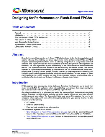
Designing for Performance on Flash-Based FPGAsimply placement constraints of the destination cells. They need care and attentive decisionas they can cause serious issues, leading to not only timing headaches, but also expensiveboard re-spins.Finally, it is needless to demonstrate the fact that the earlier these sources of timing troubles areidentified and dealt with, the sooner the timing closure can be achieved. More importantly, the effort andinvestment are less for a larger opportunity when the root cause of timing trouble is avoided or identifiedsoon. Figure 4 illustrates this theorem.As a corollary of this theorem, the best return on investment is in the order of importance associated withthe following: Quality of the RTL code Getting the best of logic synthesis by means of judicious constraints and options setting A formal link between synthesis and place-and-route Getting the best of place-and-route engines via appropriate constraining and use of the FPGAarchitecture featuresTimeEFFORTSBENEFITSFigure 4 Efforts and Opportunities vs. TimeHowever, most designs do not meet all the timing specifications and several iterations are needed. Theiterative approach that leads to timing convergence in minimal time and effort is based on the following: Analysis as a key to the identification of the aforementioned root causes of challenge A sort of these causes based on scope of implications and order of importance towards resolutionof the timing issues Dealing with these sources with an appropriate order of importance, preferably at the highestlevel of the flow—i.e., the RTL code if possibleThe "Main Sources for Design Analysis" section on page 7 summarizes the major sources for pertinentdata to identify the bottlenecks.6
Main Sources for Design AnalysisMain Sources for Design AnalysisIt goes without demonstration that not knowing the problem does not help to solve the problem. The bestway to tackle performance issues is to find clues that may lead to the root causes. The identificationprocess is not easy and is time- and effort-consuming in most cases, but a systematic approach easesthe task. Much data is already available and can be efficiently used to shorten the time and reduce theanalysis efforts. The following section will cover most of the available reports and identify the type andnature of data available in each of the reports. Moreover, the missing data is also mentioned so thatusers check other ways to build the whole picture.Synthesis Report or Log FileThe synthesis quality of results heavily affects the final post-layout timing of the design. The currentstandard synthesis report files include most of the following data: Nets with the associated fanout and buffering Register and combinatorial cells replication Number of logic levels Architecture of the arithmetic and storage or memory elements Resource utilization Number of clock domains, including explicit and derived domainsUnfortunately, the synthesis reports do not identify the congested blocks, the interconnectivity betweenblocks, nor the reasons why the synthesis process could not do some of the optimizations.Microsemi Designer Compile ReportThe backend parser performs minor netlist optimizations such as the elimination of some buffers,inverters, cells involved in dangling nets, etc. In some cases, the tool performs combining of I/Os withregisters. It also parses the user constraints and translates them into place-and-route constraints. Themain data provided in the importer report is summarized as follows: Netlist optimization results (number and type of deleted cells) Nets promoted to global networks Distribution of fanout Device resource utilization Internal and external nets fanout A limited number, generally 20, of high-fanout net candidates for promotion to a global or to asegment of the global network Internal clocksSimilar to the synthesis report, the backend compile does not report data related to blocks that aretiming-critical or those that are congested. It does not reveal any data on the interconnectivity of blocks orinter-block busses.ChipPlannerThe ChipPlanner tool helps the user to check several aspects related to the quality of the place-and-routetools. The tool allows users to check the span of the global networks in the die or whether the routeddesign is congested.Using the cell selection function of the Viewer, users can check the relative placement of hierarchicalblocks.The ChipPlanner can also help identify if the placement is inefficient. Low-fanout nets that are routed in avery sneaky way are an identification of such a poor placement. However, if the similar sneaky routing isassociated with high-fanout nets, this may be due to poor routing.Unfortunately, the user needs to know a lot more about the design before being able to use the tool toidentify block interconnects using ChipPlanner.7
Designing for Performance on Flash-Based FPGAsTiming ReportsThe timing reports are by far the most important source for information to know more about the criticalregions of the design, the inherent congestion of blocks, as well as about the quality of results ofsynthesis, placement, or routing process.The expanded paths can reveal if the paths are timing-critical because of a large number of logic levels,or because of high delay penalties associated with high-fanout nets. If these high delay penalties areassociated with low-fanout nets, this may reveal a poor placement or poor routing. If the expanded pathsare made of a long set of two-input gates, the user needs to check if this is due to a poor synthesis or apoor RTL coding style.TimingTimingUnfortunately, the timing reports do not reveal shared critical nets between paths with worst negativeslack, or negative slack distribution. Moreover, the timing reports do not report the hierarchical blocksthat meet the timing with a narrow or large margin. To see the importance of these parameters, considerthe timing profiles of two designs, given in Figure 5. A first look at the profiles will lead to the conclusionthat the design on the left is a lot more complex than the one on the right. However, a deeper look at thecommon critical nets leading to the negative slack may reveal that the number is very limited for thedesign profiled on the left. Moreover, a closer look at the profile of the design on the right shows a veryhigh sensitivity to changes in place-and-route; thus, making a decision to tackle the negative slack mayinduce a new larger set of paths with a negative slack. The moral of this illustration is that analysis mustbe deep and complete before making decisions.TargetTimingTargetTiming# PathsFigure 5 Slack/Timing Profiles for Two Different Designs or Implementations8# Paths
Ingredients for Timing OptimizationsIngredients for Timing OptimizationsBefore tackling each of the root causes of timing issues, designers are advised to revisit the RTL codeand check the various coding optimizations that they can afford. The motivation behind this preliminarystep is that a minimal effort at the RTL code level allows a large impact on the final results. The sameeffect can not be reached at the place-and-route level even if the effort deployed is two or three timeslarger. Similarly, an appropriate set of synthesis options may lead to a faster convergence if compared totedious and manual manipulation of a netlist generated with a poor set of synthesis switches.RTL Coding TipsSeveral coding styles have been published. Each of these is related to a technology, architecture, andset of tools. Table 1 gives a list of common-sense rules and should lead to a more efficientimplementation. Some of these are automatically optimized by synthesis tools. Other RTL codetechniques apply the DDR idea to speed-up the overall performance. This principle doubles the originalclock frequency using one of the available CCCs, and performs a part of the processing on one cycle ofthe doubled clock (i.e., the positive edge of the original clock) and the remaining part of the processingduring the second cycle of the doubled clock (or the negative edge of the original clock).Table 1 RTL Coding RulesOriginal CodeNew CodeA when A 0 else –ANot A 1 when A(31) else AA 1 when EN ‘1’ else AA ENX 0X(X’HIGH)X–Y 0X YX*9X SHL 3 XX * 15X SHL 4 – XDealing with High-Fanout NetsExplicit Logic Replication at the RTL LevelIn most cases, synthesis performs logic and sequential replication of the drivers blindly and withoutconsideration of the destination cells and where they belong. There are various possibilities for reducingthe fanout by explicit replication of the driver. Figure 6 illustrates an example where the explicit replicationallows flexibility of the replicated drivers to be placed closer to the internal destination cells and theexternal ones.Figure 6 Explicit Replication9
Designing for Performance on Flash-Based FPGAsIn case a block is the source of multiple high fanout nets and its size in terms of logic cells is limited (lessthan 200 VersaTiles), it is worth investigating the replication of the block itself, as illustrated in Figure 7.Sub Mod 2Sub Mod 3Sub Mod 2Sub Mod 6Sub Mod 3Sub Mod 7Sub Mod 6Sub Mod 7HighFanoutModuleSub Mod 5HighFanoutModuleSub Mod 5Sub Mod 1Sub Mod 4HighFanoutModuleSub Mod 1Sub Mod 4Figure 7 Replication of a Block Source of High-Fanout NetsIn all these cases, designers are cautioned against making these explicit replications blindly. They haveto consider this change with care and avoid replicating a driver of a generated clock domain or asynchronized reset. Failing to do so will lead to new clock domains and the headache of making surethey are mapped to low-skew routing resources, or having to analyze removal time for a large set ofsynchronized resets.Synthesis ControlSynthesis tools typically offer ways to set fanout limits globally. When available, use local, block-levelfanout control only for blocks exhibiting high net fanout.Backend Control of High-Fanout NetsThe easiest and most efficient way to deal with the delay penalty associated with high-fanout nets is tomap these nets to segments of the global networks called spines. Users must also consider theimplication of such mapping, as it involves a placement constraint on the driver and the destination cells.They need to fit in the region covered by the segment, called the scope of the spine.If the global networks are not available or if the placement constraint will introduce high congestion,users can create a so-called net region to limit the skew and the penalty associated with the net.Finally, if these two techniques do not apply, users can reset the fanout of a net and the tool will work onthe shielding of the critical ports and reducing the delay penalties.10
Ingredients for Timing OptimizationsFigure 8 illustrates the use of clock network segments to map several high fanout nets.Figure 8 High-Fanout Nets Mapped to Global Network SegmentsDealing with a High Number of Logic LevelsRevisiting RTL CodeIn some cases, the large number of logic levels is inherent to the design. Users can cope with this byadding explicit pipeline stages, adding registers when appropriate. Users may also need to re-architectthe timing of their design and anticipate data readiness one cycle ahead of the cycle where they will beprocessed, allowing two cycles for these paths if possible. Also, when RAM blocks are involved in pathswith a high number of logic levels, users can investigate the use of the pipelined configuration of the readport or anticipate the read a cycle ahead, thus allowing two cycles for these paths.Synthesis ControlThe synthesis flow allows for retiming. This register moving around the logic comes with an increase ofarea, as the number of registers may increase. Users need to watch this increase and monitor theutilization of the device resources. When the number of logic levels involves arithmetic blocks, usersneed to know that synthesis tools offer a variety of architectures for these blocks. Users need to checkthe default choice made by the synthesis tool and see whether it is an efficient architecture for the device.11
Designing for Performance on Flash-Based FPGAsBackend ControlAs part of the analysis, users need to verify the placement of the cells as well as the fanout of the netsinvolved in these paths. In case the fanout of these nets is limited, the tool offers a flexible set ofplacement constraints allowing the user to confine the placement of these paths/blocks. In case one ormore nets are associated with a delay penalty, users can use the shielding technique described above.Dealing with High CongestionThis section illustrates using an inherently congested block. On a first look at the RTL code depicted inFigure 9, the reader can easily understand the function, but most of us do not realize the underlyingcomplexity of the routing. The same complexity occurs whenever the number of logic cells needed isvery limited but the number of routes is extremely high. This is the syndrome of what is called "routingcongestion."reg [63:0] A, B, C, D, E, F, G, H, M;reg [2:0] SELECT;always @ (A or B or C or D or E or For G or H or SELECT)begincase (SELECT)3’b000 : Z A;3’b001 : Z B;3’b010 : Z C;3’b011 : Z D;3’b100 : Z E;3’b101 : Z F;3’b110 : Z G;3’b111 : Z H;EndFigure 9 Example of Routing 3:0]G[63:0]H[63:0]8:1
Ingredients for Timing OptimizationsRevisiting RTL CodeFor this particular congested block, several ideas can be investigated at the RTL code level. One of therecommended techniques is to decentralize the “routing congestion,” as suggested in Figure 10.Module 1I1I1, I2Module 1I2I3Module 2Module 2I3, I4I48:1Module 3ZI5I6Module 44:1Module 3ZI5, I6Module 4I7I7, I8I8Figure 10 MUX Decentralization TechniqueTable 2 shows the area/frequency results obtained when synthesizing the code as is, instantiating a largeMUX and implementing the recommended decentralization technique.Table 2 Centralized vs. Decentralized ImplementationsPure RTL SynthesisUsing 4:1 MUX Cores32:1, 16-bit wide MUX148 MHz(130 tiles)171 MHz(120 tiles)64:1, 16-bit wide MUX134 MHz(246 tiles)160 MHz(217 tiles)Synthesis ControlUsing the same illustration example, users must pay attention to the select lines, as the least significantbits are definitely very high-fanout nets. Moreover, the coding of the select lines, either compact orone-hot, leads to different area and speed results. Table 3 shows these results.Table 3 Compact vs. One-Hot Select Line EncodingCompact SelectOne-Hot Select64:1 – 8-bit-wide MUX134 MHz(132 tiles)163 MHz(148 tiles)64:1 – 16-bit-wide MUX130 MHz(246 tiles)158 MHz(231 tiles)As a corollary, users need to think contextually. If the select lines of the large MUX are a state register ofa FSM, the encoding of the states of this machine must be one-hot even if this encoding may not lookoptimal locally.Another synthesis control is related to resource sharing. The goal of the resource sharing is to reducedesign area by sharing large blocks by means of adding MUXes on the inputs of these blocks. Users13
Designing for Performance on Flash-Based FPGAsneed to check the implication and manage the balance between slightly higher utilization, addedcongestion, and number of logic levels.Backend ControlOne major recommendation is to avoid aggressive placement or timing constraints on these RoutingCongestion spots. In other words, users are advised to relax the placement constraints to allow higherporosity. This has to be combined with a relaxation of the timing constraints on the congested block, aswell as other non-timing-critical blocks, so that their internal nets do not come into conflict for the use of acritical routing resource.Another higher-level measure users can adopt is a more data-oriented floorplan for the blocks involved inthe congestion.Dealing with a Large Number of BussesRevisiting RTL CodeWhile the margins for maneuvering are tight, designers may revisit the design architecture for bussharing or attempt to bury some of the busses in larger blocks. Another important aspect that may makethe routing of these busses even trickier is the fanout of each of the slices of these busses. If the fanoutis not homogeneous, users are dealing with a more complex issue.Synthesis ControlUnfortunately, at the synthesis level, very little can be done to cope with these situationsBackend ControlThe most efficient physical implementation of these busses is the shortest routing possible. This involvesplacement of the drivers and the destination of each slice of the busses. If the fanout of these slices is nothomogeneous, the highest-fanout bus lines can be mapped using low-skew segments of the globalnetworks.In any case, users need to adopt a data-driven placement of the communicating blocks and relax theplacement constraints for higher porosity and ease of routability of blocks and busses.Dealing with a Large Number of Clock DomainsRevisit the RTL CodeWhile most of the clocking schemes are defined at an early stage of the system architecture cycle,designers use various techniques to handle clocking of various blocks of the design, to cope with eithertiming bottlenecks or area/resource constraints. Other designers are power-conscious and mayimplement various clocking schemes using clock MUXing or gated clocks. For all these techniques,designers must accurately assess the gain before heading up to creating/generating new clock domains.More importantly, designers need to think ahead of time and make sure that the resulting design and itsassociated clocking scheme keeps it "analysis-friendly," as the static timing analysis phase can becometedious and time consuming.Synthesis ControlThe focus of the designer should be on the setting of all the timing constraints. These include the tightestclock frequencies, the inter-clocks off-sets, the input and output delays. False paths and multi-cyclepaths are very critical and need not to be neglected.Backend ControlThe general guidelines are to separate the clock domains and adopt clock-domain-based floorplanning.This will also allow an economy of the global networks and a more effective use of the low-skewsegments of the global networks. When doing so, users need to integrate data dependency betweendomains and take into account paths optimizations.A case worthy of note is when some of the clock domains drive a large number of RAM/FIFO blocks(deep or shallow RAMs that are mapped cascading several embedded RAM blocks). In such a case,users can consider placing the RAM blocks on the top and bottom of the die, provided their performancedegradation does not affect critical paths.14
Ingredients for Timing OptimizationsDealing with a Large Number of I/OsRevisit the RTL CodeEven if the margins for maneuvering are tight at this level, designers may adopt time multiplexing andlower the number of I/Os if this is possible.Synthesis ControlUsers need to turn off the inference of registered I/Os, as this leads to an inherent placement constraintof the registers associated with these I/Os.Backend ControlUsers need to i
integration of clock synthesis circuitries inside the FPGAs, users exploit this feature to manage the clocking of several other devices on the board. The challenge with this type of design is the interdependency and the fuzzy focus of the synthesis and place-and-route engines on the clock domains. A large number of embedded memory blocks