Transcription
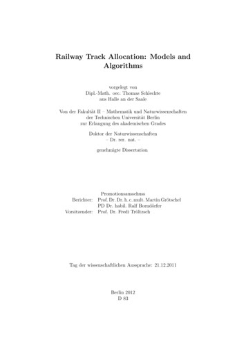
Railway Technical WebsiteBackground Paper No. 2One of a series of papers on technical issues published by the RTW from time to time. Thispaper is based on a page on the original Railway Technical Web Pages site.Track BasicsbyPiers Connor1IntroductionTrack is the base upon which the railway runs. To give a train a good ride, the trackalignment must be set to within a millimeter of the design. Track design andconstruction is part of a complex and multi-disciplinary engineering science involvingearthworks, steelwork, timber and suspension systems - the infrastructure of therailway. Many different systems exist throughout the world and there are manyvariations in their performance and maintenance. This page looks at the basics ofinfrastructure and track design and construction with drawings, photos and examplesfrom around the world. Some information was contributed by Dan McNaughton, SimonLowe and Mike Brotzman.BackgroundThe track is a fundamental part of the railway infrastructure and represents the primarydistinction between this form of land transportation and all others in that it provides afixed guidance system. The track is the steering base for the train and has evolved froman ancient design of vehicle guidance with origins dating, some historians havesuggested, from the Sumerian culture of 2000 BC. The modern railway version is basedon the steel wheel running on a steel rail. Other forms of guided vehicle technologyexist; rubber-tyred trains, magnetic levitation and guided busways, for example, butthese are not dealt with here. There is a good description of the French-based rubbertyred train technology available at The Rubber Tyred Metro website.Basic ConstructionTrack is the most obvious part of a railway route but there is a sub-structure supportingthe track which is equally as important in ensuring a safe and comfortable ride for thetrain and its passengers or freight. The infrastructure diagram here shows the principalparts of an electrified, double-track line.The total width across the two-track alignment will be about 15 m (50 ft) for a modernformation. The "cess" shown each side of the alignment is the area available for awalkway or refuge for staff working on the track.The Sub-StructureThis part of the road consists of three main elements; the formation, the sub-ballast andthe ballast. The formation is the ground upon which the track will be laid. It can be thenatural ground level or "grade" or it can be an embankment or cutting. It is importantthat the formation is made of the right materials and is properly compacted to carry theloads of passing trains.The formation under the track has a "camber" rather like that seen on a roadway. Thisis to ensure ease of water run-off to the drains provided on each side of the line. The1PRC Rail Consulting Ltd.
Background PaperTrack Basicstrack itself is supported on "ballast", made up of stones - usually granite or, in the US,basalt - below which is a layer of sand, which separates it from the formation. For newor renewed formations, the sand is normally laid over some sort of geotechnical screenor mesh to separate it from the foundation material below. In the past, asphalt or plasticsheeting has been used to prevent water seepage.Catenary masts (if the line is electrified on the overhead system) are located outside thedrains and, beyond them, there is a walkway area. This may just be a cleared path forstaff to walk safely, avoiding passing trains or, on modernised routes, a properlyconstructed path. Next to this path will be a cable trough. These were originallyconcrete but are nowadays often made of plastic. Cables crossing the track areprotected by a plastic tube, usually bright orange in the UK. Proper cable protection isessential to prevent damage by animals, track maintenance tools, weather and fire.Usually, the edge of the railway property is outside the pathway or cable runs. If the lineis built through an area requiring an embankment or cutting, the slopes will be carefullydesigned to ensure that the angle of slope will not take an excessive width of land andallow proper drainage but without risking an earth slip. The slope angle depends on thetype of soil available, the exposure, the climate and the vegetation in the area. Drainageditches are often added along the edges of cuttings and embankments. In the UK, fencesare always provided along the boundary line of the railway to protect the public fromwandering onto the track. Even so, there are a few accidents every year whentrespassers are killed or injured by trains or electric conductor rails. Many countriesaround the world don't fence their railways, assuming people will treat them like roadsand look both ways before crossing. They don't.BallastBallast is provided to give support, load transfer and drainage to the track and therebykeep water away from the rails and sleepers. Ballast must support the weight of thetrack and the considerable cyclic loading of passing trains. Individual loads on rails canbe as high as 50 tonnes (55 US or short tons) and around 80 short tons on a heavy haulfreight line. Ballast is made up of stones of granite or a similar material and should berough in shape to improve the locking of stones. In this way they will better resistmovement. Ballast stones with smooth edges do not work so well. Ballast will be laid toa depth of 9 to 12 inches (up to 300 mm on a high speed track). Ballast weighs about1,600 to 1,800 kg/cu/m. See also Ballasted vs Non-Ballasted Track below.TrackThe usual track form consists of the two steel rails, secured on sleepers (or crossties,shortened to ties, in the US) so as to keep the rails at the correct distance apart (thegauge) and capable of supporting the weight of trains. There are various types ofsleepers and methods of securing the rails to them. Sleepers are normally spaced at 650mm (25 ins) to 760 mm (30 ins) intervals, depending on the particular railway'sstandard requirements.Sleepers (Ties)Traditionally, sleepers (known as ties in the US) are wooden. They can be softwood orhardwood. Most in the UK are softwood, although London Underground uses ahardwood called Jarrah wood. Sleepers are normally impregnated with preservativeand, under good conditions, will last up to 25 years. They are easy to cut and drill andused to be cheap and plentiful. Nowadays, they are becoming more expensive and othertypes of materials have appeared, notably concrete and steel.Railway Technical WebsitePage 2Updated 10th May 2017
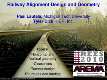
Background PaperTrack BasicsConcrete is the most popularofthenewtypes(left). Concrete sleepers aremuch heavier than woodenones, so they resist movementbetter. They work well undermost conditions but there aresome railways which havefound that they do not performwell under the loads of heavyhaul freight trains. They offerless flexibility and are allegedto crack more easily underheavyloadswithstiffballast. They also have thedisadvantage that they cannotbe cut to size for turnouts andspecial trackwork. A concretesleeper can weighs up to 320 kg (700 lbs) compared with a wooden sleeper whichweighs about 100 kg or 225 lbs. The spacing of concrete sleepers is about 25% greaterthan wooden sleepers.Another type of concretesleeper is shown in thisdrawing (left). This is thetwin-block sleeper. The designconsists of two concrete blocksjoined by a steel bar. It is 30%lighter than a regular concretesleeper, allowing it to bemoved manually. It is popularin France (where it is calledStedef) and for some lighter track forms like those used for tramway systems. Here isan example in Sheffield (below).The photo shows twin block and wooden sleepers in the same track. The sleepers shownin the above photo are supplemented with wooden sleepers at the crossover, because itis easier to cut the timber to the correct size. Sleepers at crossovers and turnouts varyin size according to their position in the layout.Steel sleepers are also now used onmore lightly used roads, but they areregarded as suitable only where speedsare 100 mi/h (160 km/h) or less.In the US most ties are made of oaksoaked in creosote, cost on averagebetween 22- 29 each. Iit used to beup to 35- 40 per tie in the late80's. They can last up to 20years. Most Class 1 RR's will replacethem after 5-10 years and then sellthem as used. Concrete ties are 42dollars. They are popular in thewestern US and on passenger lines inthe east. Recently, composite ties haveRailway Technical WebsitePage 3Updated 10th May 2017
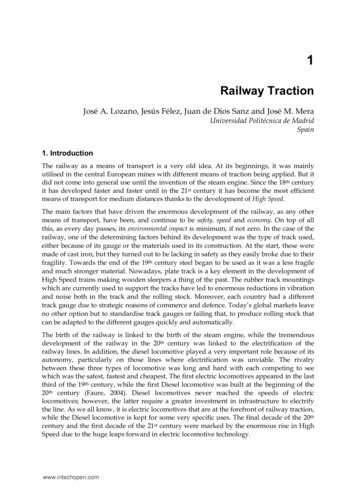
Background PaperTrack Basicscome on the market. They are made of something like old tires and recycledplastic. They can be used and spiked like regular ties, cost about 50% less and save ontrees.RailThe standard form of rail usedaround the world is the "flat bottom"rail. It has a wide base or "foot" andnarrower top or "head". The UKintroduced a type of rail which wasnot used elsewhere - apart from afew UK designed railways. This wasknown as "Bullhead" rail and isshown in comparison with thestandard type in the diagram (left.)Bullhead rail was originally designed with reuse in mind. It was intended that it wouldbe turned over when the top had worn but this proved impossible because theunderside also wore where it had been secured to the sleeper. Bullhead rail has to bemounted in a special "chair" made of cast iron and secured by a "key" wedged betweenthe rail web and the chair. The chairs are secured to the sleepers by "coachscrews". The arrangement can be seen in the first photo below:Bullhead RailsFlat bottom railThe second photo left showsa flat bottom rail clipped to abaseplateundertherail. Flat bottom rails canalso be "spiked" directly tothe sleepers. A wide headednail is driven into thesleeper on each side of therail so that the foot of therail is held by the heads ofthe spikes. Long stretches oftrack were laid in recordtimes across the US in thepioneering days of railroadRailway Technical WebsitePage 4Updated 10th May 2017
Background PaperTrack Basicsdevelopment using this method of securing rails to "ties". Nowadays, heavier loads andfaster trains require more sophisticated systems.Normally, the rail rests on a cast steel plate which is screwed or bolted to thesleeper. The rail is attached to the plate by a system of clips or clamps, depending on thedesign. The older UK standard design was an elastic spike with a sprung, curved topwhich secures the rail. There are a number of variations seen around the world. One ofthe most popular is the "Pandrol" clip seen above. A resilient pad will be providedbetween the rail and the base plate and around the securing clip, where required toprovide insulation for the track circuits, if installed.The infrastructure owning company in the UK (currently known as Network Rail), hasadopted UIC60 rail (which weighs 60 kg/m or 125 lb/yd) as its standard for high speedlines. The present standard is equivalent to the UIC 54 rail, which weighs about 113lbs/yd or 54 kg/m. Did you know, there are 2,400 sleepers (ties) in a mile of track?In the US, rail weight varries from 80-90 lb/yd (pounds/yard) in small yards to 100-110lb/yd on light duty track and between 130 and 141 lbs on heavy duty track. Rail of 141lbs is the new main line standard. The Pennsylvania RR used a special 155 lb/yd rail,which was the heaviest ever rolled for mainline operations. Some of it is still in placewith 8-bolt joints instead of the more usual 6-bolt joints. It is over an inch taller thancomparable 141 pound rail. Highest price steel rail costs 700 a ton (2000lbs). A 133pound rail costs 46.55 per yard (0.92 m.).Older track is jointed. In the UK, about 35% of track is still jointed, although this iscontinuously falling as new rail is installed. Rails were normally laid in standard lengthsbolted together by what are called fishplates in the UK or splices in the US. The jointsallowed sufficient space for expansion as they were provided at 60 foot intervals in theUK and 39 foot in the US, allowing them to be carried in a standard 40 ft flat wagon. Thejoints were always staggered in the US whereas the UK placed them side by side. Theresult of the US staggered joints can be seen in the curious rolling motion of freight carsrunning on poorly maintained track. The reason for the staggering is that, in the US itwas determined thatafter jointed rail has been in place for a time it starts to drop andcreates a depression. When a wheel falls into the depression and begins to climb outagain it exerts a force. If the two joints were in parallel this force would be much largerand the joints might snap. This is not considered a problem in the UK and Europe,probably because of the lighter axle loads.Nowadays,railisweldedintolonglengths, which can beup to several hundredmetres long. Expansionisminimisedbyinstalling and securingtherailsintension. Provided thetension is adjusted tothecorrectlevel,equivalent to a suitablerail temperature level,expansion joints arenotnormallyneeded. Special jointstoallowrailadjustment are provided at suitable locations as shown in the photo above:Railway Technical WebsitePage 5Updated 10th May 2017
Background PaperTrack BasicsAdjustment switches are also provided to protect turnouts and at locations where achange in the rail design or size occurs.Rail tends to creep in the main direction of travel so "rail anchors" ("anti-creepers" inthe US) are installed at intervals along the track. They are fitted under the rail against abase plate to act as a stop against movement.Rail WeldingModern trackwork uses long welded rail lengths to provide a better ride, reduce wear,reduce damage to trains and eliminate the noise associated with rail joints. Rail weldingis a complex art (or science) depending on how you feel about it. There are two maintypes of welding used for rails: Thermit welding and Flash Butt welding.GaugeThe standard track gauge - the distance between the two rails - is 4 ft. 8½ in or 1435mm. but many other gauges, wider and narrower than this, are in use around theworld. Gauge is often intentionally widened slightly on curved track. There is someadditional information on Track Gauges at the Pacific Southwest Railroad Museum site.Modern Track FormsThere are now a range of modern track forms using a concrete base. They are generallyused in special locations such as tunnels or bridges where a rigid base is required toensure track stability in relation to the surrounding structures. This type of track,usually called "slab track" or "non-ballasted" track, often appears as shown in thediagram below:The earth mat is asteel mesh screenprovidedonelectrified railwaysto try to keep strayreturn currents fromconnectingtoutilities pipes andnearbysteelstructures. Earthingmust be strictlycontrolled otherwiseseriousandexpensive problems will occur, made more serious and expensive because they involveother people's property.Some slab track systems have the sleepers resting on rubber or similar pads so that theybecome "floating slab track". Floating track is used as a way of reducing vibration. HongKong Mass Transit Railway is fond of it, since its lines run through very denselypopulated areas.Ballasted vs Non-Ballasted TrackThe basic argument for different track designs will be based on the bottom line - cost;cost of installation and cost of maintenance. There are however, other issues such asenvironment - noise, dust and vibration - or engineering issues such as space, location,climate and the type of service intended for the track.There are a wide variety of track forms and systems incorporating some form ofconcrete base or support which doesn't need ballast. Almost all of these require lessRailway Technical WebsitePage 6Updated 10th May 2017
Background PaperTrack Basicsdepth of construction than ballasted track. However, the accuracy of installation mustbe higher than that needed for ballasted track. Slab track will not be adjusted afterinstallation but ballast can be packed to align track as required.The ability of ballast to allow track realignment is one of its most seriousweaknesses. The lateral movement caused by passing trains on curved track is one ofthe major causes of maintenance costs added to which is the crushing caused by axleweight and damage due to weather and water. Ballast damage leads to tracks"pumping" as a train passes and, eventually, rail or sleeper damage will occur, to saynothing of the reduced comfort inside the train and the additional wear on rollingstock. Apart from regular repacking or "tamping", ballast will have to be cleaned orreplaced every few years.Another aspect to the ballasted track design, is the dust which is caused duringinstallation and as it wears or gets crushed. It does however, offer a useful sounddeadening quality.Fixed track formations using slab track or a concrete base of some sort do not sufferfrom such problems. However, the installation of slab track is reported to cost about20% more than ballasted track. To balance this cost, the maintenance costs have beenquoted as reduced by 3 to 5 times that of ballasted track on a high speed line in Japan.If low levels of use are foreseen, or if low capital cost is a more important requirement,ballasted track would be the choice. For a heavily used railway, particularly one in astructurally restricted area like a tunnel or viaduct, non-ballasted track must be the bestoption on grounds of low maintenance cost and reduced space requirements. However,care must be taken during design and installation to ensure the best out of the system.StructuresTo ensure that the path required for the passage of trains is kept clear along the route ofa railway, a "structure gauge" is imposed. This has the effect of forming a limit ofbuilding inside which no structures may intrude. The limit includes not only things likewalls, bridges and columns but also pipes, cables, brackets and signal posts. The"structure gauge" will vary with the curvature of the line and the maximum speedsallowed along the section in question.Although the civil engineer is prevented from allowing his structure to intrude into thetrain path, the rolling stock engineer also has limits imposed on the space his train mayoccupy. This space is referred to as the "kinematic envelope". This area designates thelimits the train can move laterally and vertically along the route. As for the structuregauge, the kinematic envelope will be affected by speed and features of train design suchas the bogie suspension and special systems it may have like tilting.GaugingThe line of route has to be checked from time to time to ensure that the structures arenot interfering with the gauge. A line is always gauged when a new type of rolling stockis to be introduced. It is important to see that the small variations in track position,platform edge, cable duct location and signal equipment hasn't been allowed to creepinwards during maintenance and renewal programmes.Gauging used to be done by hand locally (and still is from time to time in specialcircumstances) but nowadays, it is mostly done with a special train. The train usedconsist of a special car with a wooden frame built almost to the gauge limits. The edgesof the frame were fitted with lead fingers so that, if they hit anything as the train movedalong, they would bend to indicate the location and depth of intrusion.Railway Technical WebsitePage 7Updated 10th May 2017
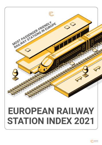
Background PaperTrack BasicsModern gauging trains are fitted with optical or laser equipment. The optical systemuses lights to spread beams of light out from the train as it runs along the line. Suitablymounted cameras record the breaks in the light beams to provide the gauginginformation. The train can run at up to 50 mi/h (80 km/h) but, of course, the runs haveto be done at night. Laser beams are also used but, as they rotate round the train andform a "spiral" of light, the method suffers from gaps which can allow intrusions to bemissed.Monuments and Datum PlatesAlong the line of route various locations are marked by a fixed post in the track or aplate on a nearby structure to indicate the correct level or position of the track. Theseare called monuments or datum plates. Measurements are taken from these to confirmthe correct position of the track.CurvesCurves in the track are almost a science on their own. Careful calculations are requiredto ensure that curves are designed and maintained properly and that train speeds areallowed to reach a reasonable level without causing too much lateral stress on the trackor inducing a derailment. There are both vertical curves and horizontal curves. There isalso a section of track on either side of a curve known as the transition, where the trackis changing from straight to a curve or from a curve of one radius to one of anotherradius.CantCant is the name used to describe the cross level angle of track on a curve, which is usedto compensate for lateral forces generated by the train as it passes through the curve. Ineffect, the sleepers are laid at an angle so that the outer rail on the curve is at a higherlevel than the inner rail. In the US, it is known as superelevation.Of course, there will usually be trains of different types, permitted speeds at differentlevels, which travel the same curve. Also, there will be occasions when trains stop onthe curve. This means that the degree of cant has to be fixed at a compromise figure toallow the safety of stopped trains and the best speeds for all the trains using the curve.In practice, faster trains are allowed to travel round the curve at a speed greater thanthe equilibrium level offered by the cant setting. Passengers will therefore feel a lateralacceleration similar to what they would feel if there was no cant and the train wastravelling at a lower speed round the curve. The difference between the equilibriumcant required by the higher speed and the actual cant is known as the cant deficiency.Cant is measured either in degrees or in linear dimensions. On standard gauge track(1435 mm or 4ft. 8½ins.) 150 mm or 6 ins. of cant is equal to 6 degrees. This is thenormal maximum in the UK. The maximum amount of cant deficiency allowed is 110mm (4½ ins.).TurnoutsI have used the word "turnout" to describe the junctions in trackwork where linesdiverge or converge so as to avoid "points" (UK) or "switches" (US), both of which termscan be confusing. In the railway "trade", turnouts are referred to as "switch andcrossing work". A turnout (diagram below) consists of a number of parts as follows:Railway Technical WebsitePage 8Updated 10th May 2017
Background PaperTrack BasicsThe moving part of the turnout is the switch "blade" or "point", one for each route. Thetwo blades are fixed to each other by a tie bar to ensure that when one is against itsstock rail, the other is fully clear and will provide room for the wheel flange to passthrough cleanly. Either side of the crossing area, wing and check rails are provided toassist the guidance of the wheelsets through the crossing.CrossingsThe crossing can be cast orfabricated. Rails are usually madeof steel with a large iron content buta little manganese is added tocrossings and some heavily usedrails to increase resistance towear. Below is a photo of anexample of a cast manganesecrossing. A crossing is alsosometimes referred to as a "frog".Types of TurnoutsThere are a number of standard layouts or types of turnouts, as shown in the followingdiagrams.Railway Technical WebsitePage 9Updated 10th May 2017
Background PaperRailway Technical WebsiteTrack BasicsPage 10Updated 10th May 2017
Background PaperTrack BasicsThese can be found anywhere but the trend is to make layouts as simple as possible inorder to reduce installation and maintenance costs. The more complex layouts areusually only used where space is limited.Examples of TurnoutsThe uses of turnouts are wide ranging and cover many variations. A few examples areoffered below to show the diversity available.Trap Points are provided atthe end of a siding or loopline to protect the main linefrom a train or vehicleswhichaccidentallypassbeyond the limits of thesiding. They are normallyunpowered trailing points, i.e.they allow a train to passsafely through one directionbut will cause the train to bederailed if it passes in thewrong direction.Similar points called CatchPoints were often provided atthe lower end of a gradient toderail runaway vehicles. Inthe photo shown here, thepoints are provided at thelimit of authorised shunting.High Speed SwitchHigh Speed trains requirehigh speed turnouts. InJapan, the so-called "bullettrain" or "Shinkansen" hasspecialroutesandtrackwork. Turnouts aredesigned for 160 km/h (100mi/h) operation. In theexample shown here, thereare seven point motors tooperate the very long andRailway Technical WebsitePage 11Updated 10th May 2017
Background PaperTrack Basicsheavy switch blade. Similar turnouts are provided for the TGV high speed lines inFrance.Switched CrossingA switched crossing (sometimes referred to as a swing nose crossing or moveable frog)will normally be provided for turnouts with a very acute angle. The crossing will have apowered element which will be set for the required route at the same time as the switchblade is set.The blades of aturnout are normallymoved remotely usinganelectricallyoperatedpointmachine.Themachine contains thecontactswhichconfirm the points aremoved and locked inthe correct positionfortherouteset. Point machinesare normally locatedto one side of thetrack but a newgenerationofmachinesisnowappearing where themechanismiscontained in a sleeper fitting between the rails.US Switch MachineIn some parts of the US.electro-pneumaticpoint machines areused.Theyarereferred to as switchmotors. The LondonUnderground also usede.p.motors.Theyrequire an air main tobe laid alongside thetrack and compressorsto supply the air. Theycanalsocauseproblemswithcondensation due toclimatic changes. Thisphoto also shows aheater used to keep theturnout blades free of ice and snow during bad weather.Railway Technical WebsitePage 12Updated 10th May 2017
Background PaperTrack BasicsSources:Railway Age; Modern Railways; International Railway Journal; Railway GazetteInternational; Mass Transit; Trains Magazine.Railway Technical WebsitePage 13Updated 10th May 2017
Railway Technical Website Background Paper No. 2 Track Basics by Piers Connor1 Introduction Track is the base upon which the railway runs. To give a train a good ride, the track alignment must be set to within a millimeter of the design. Track design and construction is part of a complex and multi-disciplinary engineering science involving