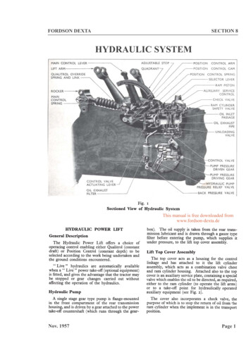
Transcription
Fordson Dexta TractorForewordThis Manual has been prepared for express purpose of assisting those concerned with theservicing and repair of the Fordson Dexta Tractor.You will find that it is divided into 10 sections, each section being, as far as possible,self-contained, with pages numbered consecutively within the section. Each page also bears thedate of issue so that when changes necessitate alterations in the contents the page can be removedand replaced by a new one containing the revised information.No attempt has been made to elaborate on established engineering principles and design butfor those who are meeting the Fordson Dexta for the first time the operation of new features andrepair procedures have been fully explained.Not even the most experienced mechanic can be expected to carry in his head all the details offits, clearances and specifications applicable to this tractor, therefore such information has beenincluded in each section of the Manual.Methods of repair based on the experience of Service Department, Tractor Division, arecovered in full detail and where necessary, particular operations are illustrated. “Exploded” andsectioned views of the main components have been included to assist correct assembly.Particular attention has been given to the application of specialised tolls and equipment whichhave been developed to ensure speedy and efficient overhaul of the tractor and a new tool numberingsystem has been introduced to clarify and make easy the section of adaptors for the main tools.Whenever reference is made in the Manual to right-hand or left-hand of the tractor thisis as viewed from the driver s seat facing forward.The tractor serial number is stamped on the left-hand side of the clutch housing/engine flangeand is pre-fixed by the number, i.e. 957E.The engine serial number is stamped on the left-hand side of the cylinder block adjacent to thewater inlet elbow from the water pump.The fuel injection pump serial number is stamped on the left-hand side (front) of the pumpcambox.Reference should be made of the tractor serial number on all correspondence relative to thistractor and, where necessary, engine and pump serial numbers should also be quoted.Ford policy is one of continuous improvement, and the right to change prices, specifications andequipment at any time without notice is reserved.Free Download fromwww.fordson-dexta.deFord Motor Company Limited,Service Department,Tractor Division,Dagenham,ngland
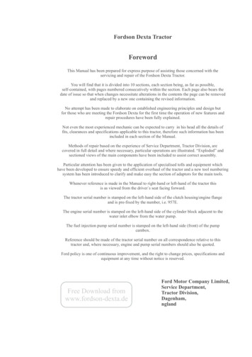
FORDSON DEXTASECTION 1BRAKING SYSTEMFree Download fromwww.fordson-dexta.deFig. 1Exploded View of Braking System1 Brake Pedal2 Pedal Kocking Latch3 Brake Cross-shaft4 Brake Cross-shaft Lever5 Brake Cross-shaft Oil Seal6 Brake Rod Clevis7 Brake Rod8 Brake Camshaft Lever9 Parking Brake Sector10 Brake Camshaft11 Anchor Pin12 Anchor Pin Plate13 Anchor Pin Washers14 Brake Back Plate15 Brake ShoesDESCRIPTIONThe rear wheels of the tractor are equipped withtwo-shoe internal expanding brakes operating in14 in. drums. The brake linings are bonded to theshoes in production, but the shoes are drilled toenable replacement linings to be riveted to the shoesshould they be required in service.The brakes are operated independently by twopedals on the right-hand side of the tractor througha suitable linkage. The left-hand brake pedal is,however, fitted with a locking pin which can beengaged with the right-hand pedal so that the brakeswill operate together. This pedal lock should alwaysbe engaged when the tractor is used on fast roadwork.Jan. 195816 Brake Adjuster Wheel17 Holder Down Pin18 Secondary Springs19 Retracting Spring20 Adjuster End Spring21 Brake Lining22 Adjustable Steady PostFor parking purposes the brakes may be locked“on” by a pawl on the right-hand brake camshaftwhich can be engaged, by means of a latch, with afixed sector on the transmission housing (Fig.2).To lock both brakes “on” for parking the pedallock should first be engaged and the pedals depressedwhile the latch is moved rearwards to engage thepawl in the sector.BRAKE ADJUSTMENTWear will take place on the brake linings due tonormal usage and it will be indicated by a gradualincrease in pedal travel before effective braking isobtained. This will be noticeable also during theinitial bedding-in of the shoes. If operatingPage 1
FORDSON DEXTABRAKING SYSTEMSECTION 1conditions are such that one brake is consistentlyused more than other, uneven wear will takeplace and the tractor will tend to pull to one sideif the brakes are applied when the pedal lock isengaged.The brake adjustment for normal lining wearshould be carried out as follows:1. Release the parking latch and jack up eachwheel in turn to adjust.2. Slide back the plate covering the adjusteraperture at the rear of the brake plate and, using ascrewdriver, turn the notched adjuster wheel towardsthe rear of the tractor to expand the brake shoe inthe drums (see Fig. 3).3. Continue until a definite drag is felt when thewheel is turned, then slacken back the adjuster untilthe wheel is just free to revolve.4. Repeat at the opposite wheel an finally roadtest the tractor to check brake operation.Check the brakes for signs of pulling to one side orover-heating due to the shoes “dragging”, andreadjust if necessary. Close the adjuster aperturecover plates.MAJOR BRAKE ADJUSTMENTWhen new brake shoes are fitted or when theadjustable steady posts have been disturbed, it isnecessary to carry out the following major adjustmenton each brake.1. With the rear end of the tractor completelyjack up and the wheels removed, disconnect thebrake rods from the pedal at their front ends andensure that the brake camshafts are free to rotate.Fig. 2Applying the Parking LatchJan. 1958Fig. 3Adjusting the brakes2. To obtain an approximate setting for the adjustable steady posts, slacken off the locknuts and unscrewthe posts (anti-clockwise) until they come out ofcontact with the shoes. The shoes will then remainagainst the fixed steady posts on the back plate.Screw in the adjustable steady posts until the brakeshoes are lifted just clear of the fixed posts.3. Carry out the brake minor adjustment previouslydescribed to establish a small shoe to drum clearance.4. Working on one shoe at a time screw in thesteady post clockwise until one edge of the brakelining contacts the drum causing in to drag. Next,turn the steady post anti-clockwise, again turningthe drum by hand to check for dragging, and countingthe number of turns on the steady post before theopposite edge of the shoe contacts the drum andcauses it to drag. Finally, screw in the steady posthalf the number of turns counted and tighten thelocknut.5. Expand the brake shoe fully in the drums priorto reconnecting the brake linkage.6. Block up the brake pedals in the raised positionand slacken off the locknuts on the clevises at thefront end of the brake rods.7. Lightly pull on the front end of the brake rodsto take up any free play in the linkage and adjust theclevises by screwing them along the rod as required,to line up the holes in the clevis with the hole in thebrake pedal lever (or cross-shaft lever for left-handside rod)8.Fit the clevis pin, split pin securely and tightenthe clevis lock nut.9.Complete the adjustment by slackening back theadjuster unit on each brake assembly until the drumsare free to turn without binding.Page 2
FORDSON DEXTABRAKING SYSTEMSECTION 1all shoes should me marked on dismantling so thatif they are only part worn they can be reassembledin the correct location.5. To remove the brake camshaft:(a) Unscrew and remove the brake camshaftlever cotter bolt and slide the lever off the end ofthe shaft. Note that the lever is further securedby means of a Woodruff key which should becarefully removed from the keyway in the shaft(b) Slide the camshaft over plate and retainingspring along the shaft and remove the shaftthrough the hole in the back plate.6. Remove the anchor pin washers from the anchorpins. If the anchor pins are worn they may beremoved by unscrewing the large nut securing themto the back plate and driving out the pins.Free Download fromwww.fordson-dexta.deFig. 4Brake Shoes and Springs10. Finally, refit the wheels and drive the tractor totest of equal braking on both wheels and signs ofoverheating. Readjust if necessary on the brakeadjuster wheels.Once the brake linkage has been set as describedabove with the brake shoes expanded in the drums,it should not be necessary to alter the brake rodsettings between major overhauls.BRAKE OVERHAULTo DismantleJack up the rear end of the tractor and remove thewheel weights (if fitted) and wheels. Unscrew thetwo countersunk screws on each brake drum andremove the drums. If necessary, slacken back thebrake adjuster to move the brake shoes clear of thedrums to facilitate removal. Disconnect and removethe brake rods.Each brake assembly should then be furtherdismantled as follows:1. Disconnect the two secondary springs from theanchor pins. Brake spring pliers can be used for thisoperation or alternatiely a length of strong flexiblewire looped around the spring end and used to expandthe spring will facilitate removal.2. Detach the anchor pin plate.3. Pull the rear ends of the two brake shoes apartand lift out the brake adjuster unit. The adjusterend spring may then be detached from the shoes.4. Remove the four hold down pins, springs andcups by compressing the outer cup inwards againstthe spring and turning through a quarter turn. Thebrake shoes may the be removed complete with theretracting spring. All four shoes are identical butas each shoe will have “bedded-in” to the drum,Jan. 1958Inspection of PartsClean all parts, inspect and renew a necessary.1. The brake shoes should not be refitted if wornto less than 1/16 in. thick at any point. The liningsare bonded to the shoes in production, but the shoesare drilled to enable linings to be riveted in positionin service. When inspecting riveted linings thewear limit allowed should be 1/16 in.(1,5 mm) abovethe heads of the rivets.2. If the anchor pins are badly worn on one sidethey may be turned through an angle to equalisewear by slackening the securing nut. Tighten thenut securely after adjustmentto a torque of 150lbs.ft. (200 Nm)3. Check the brake springs and discard if theyshow signs of being weakened or if the spring endsare deformed.Fig. 5Back Plate and Anchor PinsPage 3
FORDSON DEXTABRAKING SYSTEMFree Download fromwww.fordson-dexta.deReassemblyOn reassembly the anchor pins and washers,adjuster unit and the brake cam should be lightlylubricated with a zinc base grease. Do not usegeneral purpose grease as it may melt under hightemperatures and run onto the shoes.1. Refit the anchor pins if removed. Grease thethreads before fitting the spring washers and nutsand tighten to a torque of 150 ft.lbs(200 Nm).Place the anchor pin washers in position on theanchor pins.2. Pass the brake camshaft through the back platefrom the outside and fit the camshaft cover andretaining spring. Ensure that the camshaft leverWoodruff key and keyway are not demaged orburred and slide the lever onto the shaft. Secureby means of the cotter bolt.3. Note that if the brake shoes are to be replacedwithout new linings being fitted they should bereplaced in the same position from which they wereremoved. Fit the large retracting spring betweenthe forward ends of the shoes and install the shoeson the anchor pins.4. Fit the four hold down pins. Pass the pinsthrough the back plate and the holes in the shoe andinstall the inner cup washer and the hold downspring. Press the outer cup washer inwards againstthe spring tension and turn through a quarter of aturn to lock the pin. The spring cup washers shouldbe fitted with the convex face contacting the springend.5. Fit the adjuster end spring and install the brakeadjuster unit between the rear ends of the brakeshoes so that the notched wheel is in line with theadjusting slot in the back plate.6. Position the anchor pin plate over the ends ofthe anchor pins and fit the two secondary springs.A lenght of flexible wire will again facilitate extendingthe springs to fit the hooked ends around the anchorpins.7. Replace the brake drums and secure in positionusing the two countersunk screws.8. Carry out the major brake adjustment previouslydescribed.TO RENEW THE BRAKE BACK PLATETo renew a brake back plate it is necessary toremove the axle shaft and bearing retainer from theaxle housing and the procedure for carrying out thiswork is described fully in the Rear axle sectionunder the heading “To Remove an Axle Shaft”.In addition to the operations listed, the brake shoesmust be removed as detailed under”BrakeOverhaul”.It will be noted that a number of steel shims arefitted between the brake back plate and the axlehousing at both sides of the tractor to provide anadjustment for axle shaft end float. The two axleJan. 1958SECTION 1shafts being in direct contact at the centre of thedifferential, the end float of both shafts can beadjusted simultaneously by altering the shim thickness at either side of the axle. If a new back plate isfitted then, due to possible slight differences in thethickness of the old and the new back plates, theend float on the shafts may be altered and this shouldtherefore be checked and readjusted if necessary.Refer to the Rear Axle section for full informationon this adjustment.BRAKE PEDALS AND LINKAGEBoth brake pedals pivot on a common shaft whichpasses through the clutch housing, where it issupported by two bronze bushes.The right-hand side pedal turns on the shaft ontwo steel-backed bronze bushes, which are spacedapart. The left-hand side pedal is interposedbetween these bushes and is locked to the shaft bya drive fit cotter pin. A lubricator is fitted into theend of the shaft and is connected to the pedal bushesby suitable drillings.At the left-hand end of the cross-shaft is securedthe cross-shaft lever so that when the left-handpedal is depressed, the lever moves forward actuatingthe left-hand brake rod and camshaft.Rubber oil seals a
Fordson Dexta Tractor This Manual has been prepared for express purpose of assisting those concerned with the servicing and repair of the Fordson Dexta Tractor. You will find that it is divided into 10 sections, each section being, as far as possible, self-contained, with pages numbered consecutively within the section. Each page also bears the date of issue so that when changes necessitate .