Transcription
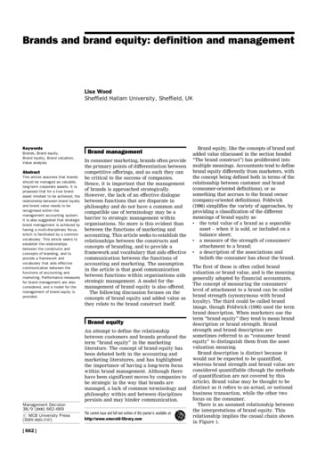
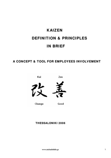
Glossary // 9DEFINITION // ICONSALLOY DEVELOPMENTAUTOMOTIVER&DTEMPERATURE MEASUREMENTINDUSTRIALMEASUREMENT SYSTEMSCURRENT MEASUREMENTSMART GRIDAEROSPACESIGNAL AND CURRENTTRANSMISSIONIT TECHNOLOGYRAIL ENGINEERINGJOINING TECHNOLOGYRENEWABLE ENERGYDRIVE TECHNOLOGYHEAT GENERATIONMEDICAL ENGINEERING01
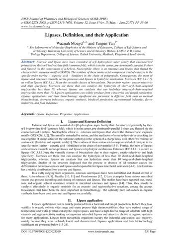
Glossary // 9GLOSSARY OF TERMSTHERMOCOUPLEA thermocouple consists of two dissimilar electrical conductorsthat are connected in an electrical circuit. If their junctions are atdifferent temperatures, a thermoelectric voltage will result (knownas the “Seebeck effect”). This generated voltage is caused by theelectron drift in the single legs resulting from the temperature difference over the length of the single conductors (legs) which form thethermocouple. Since the generated EMF of a single leg cannot bemeasured, two single leg materials with different electrical characteristics (number of electrons, binding energy, etc.) will be required touse the Seebeck effect for temperature measurement. The measuredthermoelectric voltage is the difference of the generated single legEMF. A thermocouple is an instrument (converter) by means ofwhich heat energy is converted into electrical energy, i.e. a currentor voltage generator. Thermoelectric voltage is used as a measuringsignal. The voltage produced is solely dependent on the materialand on the temperature difference to which the thermocouple isexposed. It is independent of the conductor’s form or its dimensions.The thermoelectric power produced in a thermoelectric circuit is theproduct of thermoelectric current and the thermoelectric voltage.If the resulting voltage is measured with the lowest possible current(using temperature or DVM’s with a very high internal resistance), itwill be a direct measurement of the temperature difference to whichthe thermocouple is exposed. Due to the fact that only a temperaturedifference is measured, the temperature of the reference junction hasto be well known.Identification of the thermocouplesin accordance with IEC 60584Thermocoupleclassification letter of the thermocouple typeExampleK for NiCr-NiSingle leg plus polarity identification (“P“ or “N“)EXTENSION LEADSince it is difficult or impossible to directly connect the thermocouple to the transducer for reasons of cost or handling, an extension or compensating lead is frequently connected as an extensionbetween the thermocouple and the transducer. The extension leadsupplies the same thermoelectric voltage in a limited applicabletemperature range and has the same nominal chemical compositionas the thermocouple. The temperature range used is limitedhowever. The total thermoelectric voltage supplied results fromthe thermoelectric voltage of the thermocouple in the temperaturerange between measuring point and the junction thermocouple/extension lead and thermoelectric voltage generated by the extension- or compensating lead between the junctions of thermocouple/extension lead and extension lead/transducer.Identification of the extension leadin accordance with IEC 60584Extension lead classification letter of the correspondingthermocouple type plus letter “X“ (extension)Example KX for NiCr-Nithermocouple type KSingle leg classification letter of the correspondingAs perextension lead type plus polarityIEC 60584identification (“P“ or “N“)plus letter “X“ (extension)Example KPX for NiCr-Nipositive leg of the extension lead typeCOMPENSATING LEADA compensating lead is, by its function, an extension lead.A compensating lead however, shows a completely differentchemical composition. The application range of temperatures isalso limited here. Using compensating leads may result in aslightly higher increase of errors than with extension leads.Since the sum of thermoelectric voltages in a thermoelectriccircuit is equal to the sum of all single thermocouples connectedin series, such a measuring circuit can also be formed from athermocouple and a compensating lead.Identification of the compensating leadin accordance with IEC 60584Compensating lead classification letter of the corresponding thermocouple type plus letter “C” (Compensating)Example KC for NiCr-Ni, compensating lead type KSingle leg classification letter of the correspondingAs perthermocouple type plus polarity identificationIEC 60584(“P“ or “N“) plus letter “C“ (Compensating) plusletter “A” or “B” for different types of compensating leadsExample KPCA for NiCr-Nipositive leg of compensating lead type KFor any further information regarding the physical principles,possible errors and the avoidance thereof, or to any of the key words listed, please contact us at thermo@isabellenhuette.de orvisit our homepage www.isabellenhuette.de02
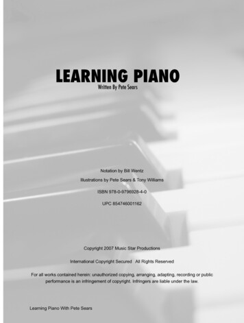
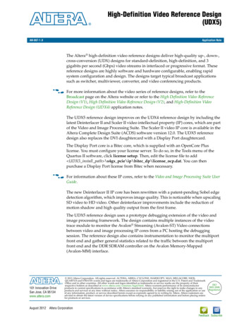
Glossary // 9MATERIALS FOR THERMOCOUPLESStandards for basic values of thermoelectric voltageStandardAs perStatusThermocouple typeKNEJTIEC 60584*ITS 90valid ASTM E 230ITS 90valid DIN 43710IPTS 68withdrawnGOST P.8.585-2001ITS 90valid NIST Monograph 1751)ITS 90valid NBS Monograph 1251)IPTS 68replaced by NISTMonograph 175 LU We supply in accordance with the standards specified above. If you require special standards, older issues of the specified standardsor your own customer’s specifications, please contact us.1) Basic values without assignment to tolerances. Applicable norm for indicated type. Indication of the related standards for the different thermocouple types.* As well as the respective national translation of EN 60584. In this connection, the national standard designation will be added to EN 60584 (e.g. DIN EN 60584).03
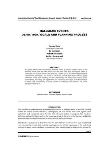
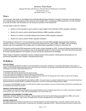
Glossary // 9MATERIALS FOR THERMOCOUPLESTOLERANCES ACCORDING TO THE INDICATED STANDARDSTable 1 // IEC 60584Stand- MaterialardsymbolTemperaturerange class 1in CToleranceclass 1Temperaturerange class 2in CToleranceclass 2Temperaturerange class 3in CToleranceclass 3Permissibletolerance (notin standard)*KISATHERM PLUSISATHERM MINUS– 40 to 1,000 1.5 C or 0.4 % (t 90)– 40 to 1,200 2.5 C or 0.75 % (t 90)– 200 to 40 2.5 C or 1.5 % (t 90)NNICROSILNISIL– 40 to 1,000 1.5 C or 0.4 % (t 90)– 40 to 1,200 2.5 C or 0.75 % (t 90)– 200 to 40 2.5 C or 1.5 % (t 90)EISATHERM PLUSISOTAN – 40 to 800 1.5 C or 0.4 % (t 90)– 40 to 900 2.5 C or 0.75 % (t 90)– 200 to 40 2.5 C or 1.5 % (t 90)JIRONISOTAN – 40 to 750 1.5 C or 0.4 % (t 90)– 40 to 750 2.5 C or 0.75 % (t 90)TE-COPPERISOTAN – 40 to 350 0.5 C or 0.4 % (t 90)– 40 to 350 1.0 C or 0.75 % (t 90)– 200 to 40 1.0 C or 1.5 % (t 90)Table 2 // ASTM E230Stand- MaterialardsymbolTemperature range in C(t90)Tolerances standardTolerances specialPermissible tolerance(not in standard)*KISATHERM PLUSISATHERM MINUS0 to 1,260 2.2 C or 0.75 % (t 90) 1.1 C or 0.4 % (t 90) 0.55 C or 0.2 %NNICROSILNISIL0 to 1,260 2.2 C or 0.75 % (t 90) 1.1 C or 0.4 % (t 90) 0.55 C or 0.2 %EISATHERM PLUSISOTAN 0 to 870 1.7 C or 0.5 % (t 90) 1.0 C or 0.4 % (t 90) 0.5 C or 0.2 %JIRONISOTAN 0 to 760 2.2 C or 0.75 % (t 90) 1.1 C or 0.4 % (t 90) 0.55 C or 0.2 %TE-COPPERISOTAN 0 to 370 1.0 C or 0.75 % (t 90) 0.5 C or 0.4 % (t 90) 0.25 C or 0.2 %Table 3 // DIN 43710 (withdraw)Stand- MaterialardsymbolTemperature range in C(t90)Tolerances standardPermissible tolerance(not in standard)*LIRONISOTAN – 200 to 900 3.0 C or 0.75 % (t 68) 1.5 C or 0.375 %UE-COPPERISOTAN – 200 to 600 3.0 C or 0.75 % (t 68) 1.5 C or 0.375 %Table 4 // Measuring range ISAToleranceClass 1/2 respectively Standard/Special and not standardised toleranceUpon requestRangeType– 40 C0 to 1,200 CK N E J T 0 to 400 C* Please expect longer delivery times for these tolerances. Applicable norm for indicated type.0 to 700 C 0 to 1,000 C– 200/ 40 C LUClass 3Standard 04
Glossary // 9MATERIALS FOR EXTENSION LEADSStandards for basic values of thermoelectric voltageStandardStatusThermocouple typeKXEXJXTXNXIEC 60584valid ASTM E 230valid GOST P.8.585-2001validDIN 43710withdrawnLXUXNo compensating leads are specified in the GOST P.8.585-2001.Here the tolerances of the elements are assumed.No compensating leads arespecified in the DIN 43710.Here the tolerances of theelements are assumed.We supply in accordance with the standards specified above. If you require special standards, older issues of the specified standardsor your own customer’s specifications, please contact us. Applicable norm for indicated type.05
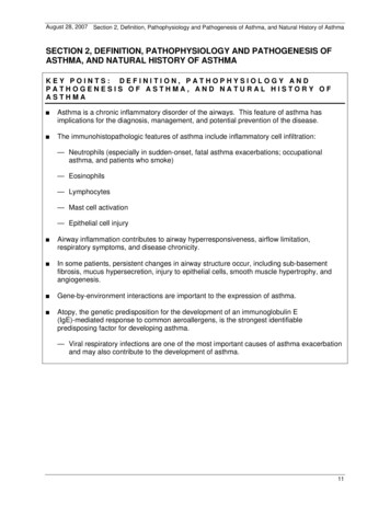
Glossary // 9MATERIALS FOR EXTENSION LEADSTOLERANCES ACCORDING TO THE INDICATED STANDARDSTable 1 // IEC 60584Stand- MaterialardsymbolCable temperaturerange in C (t 90)Tolerance class 1Tolerance class 2Permissible tolerance(not in standard)*Measuring junctiontemperature in CKXISATHERM PLUSISATHERM MINUS– 25 to 200 60 μV ( 1.5 C) 100 μV ( 2.5 C) 30 μV 900NXNICROSILNISIL– 25 to 200 60 μV ( 1.5 C) 100 μV ( 2.5 C) 30 μV 900EXISATHERM PLUSISOTAN – 25 to 200 120 μV ( 1.5 C) 200 μV ( 2.5 C) 60 μV 500JXIRONISOTAN – 25 to 200 85 μV ( 1.5 C) 140 μV ( 2.5 C) 50 μV 500TXE-COPPERISOTAN – 25 to 100 30 μV ( 0.5 C) 60 μV ( 1.0 C) 15 μV 300Table 2 // ASTM E230Stand- MaterialardsymbolCable temperaturerange in C (t 90)Tolerances standardTolerances specialPermissible tolerance(not in standard)*KXISATHERM PLUSISATHERM MINUS0 to 200 2.2 C 1.1 C 0.55 CNXNICROSILNISIL0 to 200 2.2 C 1.1 C 0.55 CEXISATHERM PLUSISOTAN 0 to 200 1.7 C 1.0 C 0.5 CJXIRONISOTAN 0 to 200 2.2 C 1.1 C 0.55 CTXE-COPPERISOTAN – 60 to 100 1.0 C 0.5 C 0.25 CTable 3 // Measuring range ISAUpon requestRange– 25 CTypeKXStandard– 40 C 100 C 100/ 200 C NX EX JX TX * Please expect longer delivery times for these tolerances. Applicable norm for indicated type.06
Glossary // 9MATERIALS FOR COMPENSATING LEADSStandards for basic values of thermoelectric voltageStandardStatusIEC 60584validGOST P.8.585-2001validASTM E 230validASTM E 988validCompensating lead typeBCSCASCBRCARCBKCAKCBNC No compensating leads are specified in the GOST P.8.585-2001.Here the tolerances of the elements are assumed.BXBCSXRX CCDC We supply in accordance with the standards specified above. If you require special standards, older issues of the specified standardsor your own customer’s specifications, please contact us. Applicable norm for indicated type.07
Glossary // 9MATERIALS FOR COMPENSATING LEADSTOLERANCES ACCORDING TO THE INDICATED STANDARDSTable 1 // IEC 60584Stand- MaterialardsymbolCable temperature rangein C (t 90)Tolerance class 2Measuring junctiontemperature in CPermissible tolerance(not in standard)*KCAIRONISA MINUS0 to 150 100 μV ( 2.5 C) 900KCBE-COPPERISOTAN 0 to 100 100 μV ( 2.5 C) 900 50 μVNCE-COPPERISA -SIL0 to 150 100 μV ( 2.5 C) 900 50 μVRCA/SCAE-COPPERA-COPPER 110 to 100 30 μV ( 2.5 C) 1,000 22 μVRCB/SCBE-COPPERA-COPPER 110 to 200 60 μV ( 5.0 C) 1,000 30 μVBCE-COPPERE-COPPER0 to 100 40 μV ( 3.5 C) 1,400BCS-COPPER**E-COPPER0 to 200 1,400 60 μV 30 μV 33 μVTable 2 // ASTM E230Stand- MaterialardsymbolCable temperature rangein C (t 68)Tolerances standardE-COPPERA-COPPER 110 to 200 5.0 CBXS-COPPERE-COPPER0 to 200 4.2 CBCE-COPPERE-COPPER0 to 100 3.7 CRX/SXPermissible tolerance(not in standard)* 2.5 CTable 3 // ASTM E988Stand- MaterialardsymbolCable temperature rangein CTolerances standardPermissible tolerance ISA(not in standard)*CCISA -SILISOTAN 0 to 200 110 μV 55 μVDCISATHERM PLUSIRON0 to 200 110 μV 55 μVTable 4 // Measuring rangeRangeTypeRCA/SCA/KCB/BC 100 C 100/ 200 C Others * Please expect longer delivery times for these tolerances.** Not mentioned in standard. Applicable norm for indicated type.08
ASTM E 230 valid GOST P.8.585-2001 valid No compensating leads are specified in the GOST P.8.585-2001. Here the tolerances of the elements are assumed. DIN 43710 withdrawn No compensating leads are specified in the DIN 43710. Here the tolerances of the elements are assumed. We supply in accordance with the standards specified above. If you require special standards, older issues of the