Transcription
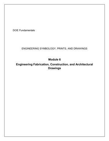
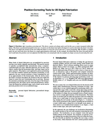
International Journal of Scientific & Engineering Research, Volume 7, Issue 4, April-2016ISSN 2229-5518429DESIGN, ANALYSIS AND FABRICATION OFGO-KARTKiral Lal, Abhishek O SAbstract— A Go-kart is a small four wheeled vehicle. Go-kart, by definition, has no suspension and no differential. They are usually racedon scaled down tracks, but are sometimes driven as entertainment or as a hobby by non-professionals. 'Carting is commonly perceived asthe stepping stone to the higher and more expensive ranks of motor sports. Kart racing is generally accepted as the most economic form ofmotor sport available. As a free-time activity, it can be performed by almost anybody and permitting licensed racing for anyone from theage of 8 onwards. Kart racing is usually used as a low-cost and relatively safe way to introduce drivers to motor racing. Many peopleassociate it with young drivels, but adults are also very active in karting. Karting is considered as the first step in any serious racer's career.It can prepare the driver for highs-speed wheel-to-wheel racing by helping develop guide reflexes, Precision car control and decisionmaking skills. In addition, it brings an awareness of the various parameters that can be altered to try to improve the competitiveness of thekart that also exist in other forms of motor racing.Index Terms— Go-kart, Racing, Design, Frame, Analysis, Steering System, Braking System, Engine, Transmission, Innovtion.—————————— ——————————1 INTRODUCTIONGo-kart is a simple four-wheeled, small engine, singlesealed racing car used mainly in United States. They wereinitially created in the 1950s.Post-war period by airmen as away to pass spare time. Art Ingels is generally accepted to bethe father of karting. He built the first kart in Southern California in 1956. From them, it is being popular all over America and also Europe.A Go-kart, by definition, has no suspension and no differential. They are usually raced on scaled down tracks, but aresometimes driven as entertainment or as a hobby by nonprofessionals. 'Carting is commonly perceived as the steppingstone to the higher and more expensive ranks of motor sports.Kart racing is generally accepted as the mosteconomic form ofmotor sport available. As a free-time activity, it can be performed by almost anybody and permitting licensed racing foranyone from the age of 8 onwards. Kart racing is usually usedas a low-cost and relatively safe way to introduce drivers tomotor racing. Many people associate it with young drivels,but adults are also very active in karting. Karting is consideredas the first step in any serious racer's career. It can prepare thedriver for highsspeed wheel-to-wheel racing by helping develop guide reflexes, Precision car control and decisionmaking skills. In addition, it brings an awareness of the various parameters that can be altered to try to improve the competitiveness of the kart that also exist in other forms of motorracing.SL.No1.2.3.4.5.6.PROPERTIESTensile strengthYield strengthBulk ModulusShear modulusYoung's ModulusPoisson's ratioIJSER2VALUES440 MPa370 MPa140 GPa80 GPa205 GPa0.290The chemical composition of the pipe is as IronPERCENTAGE0.14-.0.20%0.60-0.90 0.040 % 0.050 %98.8 - 99.26 %2.2 ProposedDesign Of The VehicleThe 3-D views of the completed vehicle are shown below.FRAME DESIGN2.1 Frame MaterialThe material used for the frame is AISI 1080 MILD /LOWCARBON STEEL as it has reasonable price and provide enoughsafety to the driver. The pipe is of 1 inch diameter having 3mmthickness. The physical properties of the pipe are as follows.The chemical composition of the pipe is as follows.IJSER 2016http://www.ijser.orgFig. Isometric view of the vehicle
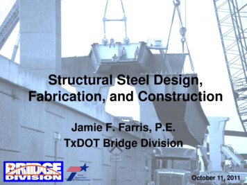
International Journal of Scientific & Engineering Research, Volume 7, Issue 4, April-2016ISSN 2229-5518.Fig. Rear view of the vehicle4302.3 Frame FEA Safety AnalysisAside from exceeding the minimum material requirement set bythe discussion in team members. Standard values of the materialare compared with the analysed result to verify the structural integrity of the frame. At critical points of the wireframe model ofthe frame, theoretically calculated loads are placed in order tostimulate the maximum force the vehicle can bear from its ownweight and the driver in the event of collision. Frame analysiswas conducted in INVENTER software. While meshing, thenumber elements was found to be 35955 with 70392 nods. Forthe conduction of finite analysis of the frame an existing designof the frame is uploaded from the computer. Three different induced load cases are considered for the calculation of stresses.Three cases were frontal impact, side impact and rear impact.Impact test on the frame is conducted according to ENCAP ( European New Car Assessment Programme). According to ENCAP,linear Velocity remains at 64 Kmph for frontal impact, 48 Kmphfor side impact and 50 Kmph for rear impact.The frame analysis calculations are done as follows.2.3.1 Front Impact AnalysisThe front impact test is carried out asMass of the vehicle (estimated) M 180 KgVelocity V 64 Km/h 17.8 m/sFrom mass moment of inertia equation,Frontal impact Force F P x TWhere,P momentum T duration of time 1.1 secondsP MxV 180 x 17.8 3204 Kgm/sF P x T 3204 x 1.1 3524.4 NIJSERFig. Side view of the vehicleFig. Front view of the vehicleFig. Top view of the vehicleNow keeping the rear part fixed the calculated force applied tothe front part of the frame in INVENTER. The image sbelowshows the results of deformation, Von-mises stress and safetyfactor respectively.Fig. DeformationThe maximum deformation is found to be 0.48 mm which isvery small and it is safer to use.IJSER 2016http://www.ijser.org
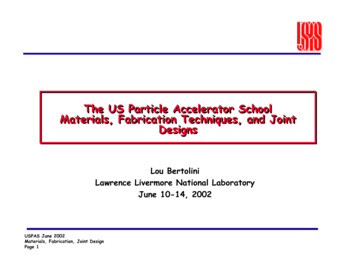
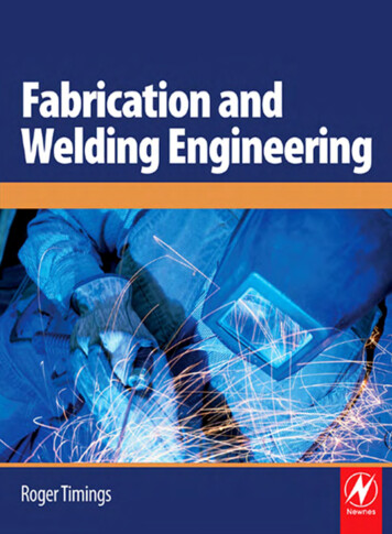
International Journal of Scientific & Engineering Research, Volume 7, Issue 4, April-2016ISSN 2229-5518Fig. Von-Mises StressMaximum stress is found to be 69.12 MPa. It is a safe value.431Fig. DeformationThe maximum deformation is found to be 0.173 mm which isvery small and it is safer to use.IJSERFig. Safety FactorFrom the analysis, safety factor is found to be 15 at the maximum, not less than 5. So it is acceptable.2.3.2 Side Impact AnalysisSide impact Force F P x Twhere P M x VM 180 KgV 48 kmph 13.3 m/sP Mx V 180 x 13.3 2394 Kgm/sF P x T 2261 x 1.1 2633.4 NNow keeping one side of the frame fixed the calculated force isapplied on the other side of the frame in INVENTER.The image below shows the result.Fig. Von-Mises StressMaximum stress is found to be 35.3MPa. It is a safe value.Fig. Safety FactorFrom the analysis, safety factor is found to be15 not less than 5.So it is acceptable.IJSER 2016http://www.ijser.org
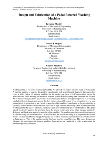
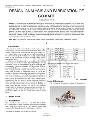
International Journal of Scientific & Engineering Research, Volume 7, Issue 4, April-2016ISSN 2229-55184322.3.3 Rear Impact AnalysisRear impact Force F P x Twhere P M x VM 180 KgV 50 kmph 13.8 m/sP Mx V 170 x 13.8 2484 Kgm/sF P x T 2346 x 1.1 2732.4 NNow keeping the front part fixed the calculated force applied tothe rear part of the frame in INVENTER. The image belowshows the result.Fig. Safety FactorFrom the analysis, safety factor is found to be 15, not less than 5.So it is acceptable.2.4 ConclusionConclusion for the safety analysis is tabulated 4 NForceNStress Gen14045.49N1088.81049.42N/erated/m2N/m2m2Total De0.48 mm1.197m0.173 mmformationmSafety fac5.35ul4.75ul10.47ultor (min)IJSERFig. DeformationThe maximum deformation is found to be 1.197 mm which isvery small and it is safer to use.Factor of safety F.O.S. Design Stress/Yield Stress3 STEERING SYSTEMThe steering system is the key interface between the driver andthe vehicle. The main objective of the steering system is to provide directional control to the vehicle with . It must be smooth,compact and light. it must also be precise and must also providethe driver a perfect control of the vehicle.Our steering system is designed to provide easy manoeuvringwith quick response and it follows Ackermann Design.Fig. Von-Mises StressMaximum stress is found to be 77.9MPa. It is a safe value.IJSER 2016http://www.ijser.org
International Journal of Scientific & Engineering Research, Volume 7, Issue 4, April-2016ISSN 2229-55183.1 CALCULATIONNo. of disc brakeDisc outer diameterDisc inner diameterThickness Brake pedal forcePedal ratioCoefficient of friction padStopping distanceStopping timeTotal brake forceTrack Width (a) 990 mmWheel Base (b) 1030 mmPivot to pivot point (c) 710 mmLet outer turning radius Ro 2600 mmWhere,433α Ackermann angle𝑇𝑇 (2 𝐴𝐴𝐴𝐴𝐴𝐴𝐴𝐴𝐴 𝑎𝑎𝑎) sin 𝛽𝐴𝐴𝐴𝐴𝐴𝐴𝐴𝐴𝐴 𝑎𝑎𝑎 494.8363 𝑚𝑚1190mm30mm3mm150N3:10.64.89m0.88s2295.225 NAt the time of braking, kinetic energy is converted into heat energy due to t he friction between calliper pad and rotor disc.1Kinetic Energy 2 𝑚𝑣 2 180 x 11.112 /2 11108.889Deceleration of the vehicle should not exceed 1.3G. µ 0.6Stopping distance of the vehicle is calculated by Newton Law's ofmotion.v2 u2 2aSwhere,v is the final velocity of the vehicleu is the initial velocity of the vehicleS is the stopping distanceS v2-u2/ 2a 11.112/2x1.3x9.8 4.84 mBreaking force K.E/S 10491.73/4.84 2295.225 NIJSERThe value of turning radius is assumed to be 2.6m. Also the values of TW and WB are 990mm and 1030mm. Substituting thesevalues, the value of Ackermann arm is found to be 519.8143mm.Now, the values of inner and outer angles are:𝑖𝑖𝑖𝑖𝑖 𝑎𝑎𝑎𝑎𝑎 𝛼1 39.047 Consider ABP,cot𝜃 BP/IP 1434/1024𝞱 35.42⁰Consider IAP,cotØ – cot𝞱 c/bcotØ 2.086yØ 25.61⁰Inner turning radius Ri (b/sin𝞱)/((a-c)/2) (1020/sin35.2)/((1058-694)/2) Ackermann angle tanα (c/2)/b (694/2)/1020α 18.7⁰The turning radius and turning angles are calculated graphicallyand arithmetically. Graphical values and arithmetical values areapproximately equal.5 POWER TRAINBRIGGS&STRATTON engine is used in making the kart.It's specifications are given keCoolingDry weightMax. PowerGross. TorqueType208.5 cc4 StrokeAir Cooled18 kg6.5bhp@3060rpm:12.9 Nm6 WHEELS4BRAKING SYSTEMA disc brake is a wheel brake that helps to slow down the speedof the vehicle by the friction caused by pushing brake against thedisc with a set of callipers. Discs are mostly made from cast iron.They are fixed on the axle. When brake calliper is forced mechanically, pneumatically or hydraulically against the both sidesof the disc, friction occurs and thus the vehicle can be stopped.The main objective of the brakes is to stop the car safely andeffectively.Wheels allow the vehicle to move smoothly on a surface. We'reusing go kart tyres having the dimensions 10X4.7X5 inches forthe front wheel and 11X7.1X5 inches for the rear whee7 INNOVATIONSELF RECOVERY SYSTEMIJSER 2016http://www.ijser.orgTwo wiper motors of high torque or moulded with thecentre of the frame with two rubber wheels connected to
International Journal of Scientific & Engineering Research, Volume 7, Issue 4, April-2016ISSN 2229-5518it.The wiper motors are then connected to the car batteryin order to get the electrical input of the motor.7.1 Component Wiper motorConnecting wiresSwitchCaster wheelsElectric jack 7.3Wiper motors are moulded with a hinge joint at the centre of the frame so as to provide the easy up and downmovement of the wheels when necessary.When the car is having any engine trouble and not working properly or the driver need to take reverse his kart,the self recovery system can be activated.By pressing the up and down switch the electric jackconnected to the rod connecting the two wipers hingejoint moves up and down and thereby lifting the rearwheels of the kart and making the wheels connected towiper then acts as the rear wheels of the car.Thus by the torque created by the wiper help to movethe kart according to drivers wish which can be controlled by the steering.Advantages 10 CONCLUSIONTo achieve the set goals, Team Raptorz used the finite element forthe evaluation, creation and modification of the best vehicle design. The prior aim of the team was to build a go kart with minimum cost without compromising the safety and performance ofthe vehicle. The final result is a desired Go Kart design meetingall the above factors.11 ACKNOWLEDGMENT7.2 Working 434Frst of all we thank God the Almighty for all his blessings andthen our parents for their support from the beginning. We takethis opportunity to thank our college, "UKF College Of Engineering and Technology, Kollam" for allowing us to use the Workshop and CAD facilities in the campus. We are very much indebted to our General Secretary and our beloved principal. Weexpress our sincere gratitude to them. We offer our heartfelt gratitude to The head of the Department, Mechanical Engineering forhis motivation and blessing. We also thank all our faculties andstudents who wished for the success of the kart.12 REFERENCESIJSER[1][2][3]In the case of emergency , if the vehicle breakdown inthe middle of the race, the system can be activated andthe driver themselves can move the vehicle to a safeplace.Kart can be driven in reverseNo human effort is needed[4][5][6]8 KILL SWITCH 9 BODY WORKS AND SEATAnbuselvi S., Chellaram C., Jonesh S., Jayanthi L., Edward J.K.P.,"Bioactive potential of coral associated gastropod, Trochus tentoriumof Gulfof Mannar, Southeastern India", Journal of Medical Sciences,ISSN : 1682-4474, 9(5) (2009) pp. 240-244.Caroline, M.L., Vasudevan, S., "Growth and characterization of anoganic nonlinear optical material: l-alanine alaninium nitrate",Materials Letters, ISSN : 0167-577X, 62(15) (2008) pp.2245-2248.Parvez Hussain S. D, C. N. Veeramani, B.Amala Priya Shalini, R.Karthika, “An Innovative Energy Efficient Automobile Design,"InternationalJournal of Innovative Science and Modern Engineering(IJISME).ISSN: 2319-6386, Volume-2 Issue-10, September 2014.Arumugam, S., Ramareddy, S., "Simulation comparison of classD/Class E inverter fed induction heating", Journal of Electrical Engineeing, ISSN : 1335-3632, 12(2) (2012) pp. 71-76.Simon McBeath, Gordon Murray, "Competition Car Down force -APractical Handbook"Mes Paolino, Alexander Jadczak, Eric Leknes and Tarek Tantawy,"The S-90 Go-Kart-Optimal Design Report, NSF Projects. Ashford.Kill switch is provided in our vehicle in order to provide safety tothe driver. In case of any emergency the driver can push the killswitch so that the engine would stop functioning. The electronicsare designed so that when the kill switch is depressed, power isdisabled on primary ignition coil of the engine.9 BODY WORKS AND SEATBody works are fabricated in moulding workshops as per thedesign. Go kart seat which is adjustable gives extra safety andcomfort to the driver as per their heights and position to the driver when compared to the normal seats. Body works give an exterior appearance and provide some safety.IJSER 2016http://www.ijser.org
It can prepare the driver for highs-speed wheel-to-wheel racing by helping develop guide reflexes, Precision car control and decision-making skills. In addition, it brings an awareness of the various parameters that can be altered to try to improve the competitiveness of the kart that also exist in other forms of motor racing.