Transcription
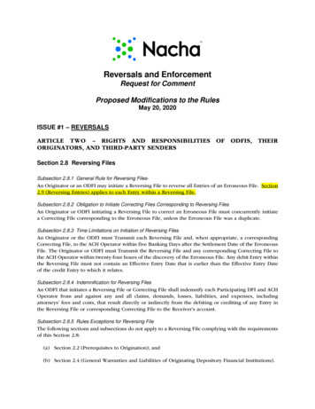
Position-Correcting Tools for 2D Digital FabricationAlec RiversMIT CSAILIlan E. MoyerMIT(a)Frédo DurandMIT CSAIL(b)(c)Figure 1: Overview: (a): A position-correcting tool. The device consists of a frame and a tool (in this case a router) mounted within thatframe. The frame is positioned manually by the user. A camera on the frame (top right in the figure) is used to determine the frame’s location.The device can adjust the position of the tool within the frame to correct for error in the user’s coarse positioning. (b): To follow a complexpath, the user need only move the frame in a rough approximation of the path. In this example, the dotted blue line shows the path that thetool would take if its position were not adjusted; the black line is its actual path. (c): An example of a shape cut out of wood using this tool.1AbstractMany kinds of digital fabrication are accomplished by preciselymoving a tool along a digitally-specified path. This precise motionis typically accomplished fully automatically using a computercontrolled multi-axis stage. With that approach, one can only createobjects smaller than the positioning stage, and large stages can bequite expensive. We propose a new approach to precise positioningof a tool that combines manual and automatic positioning: in ourapproach, the user coarsely positions a frame containing the toolin an approximation of the desired path, while the device tracksthe frame’s location and adjusts the position of the tool within theframe to correct the user’s positioning error in real time. Becausethe automatic positioning need only cover the range of the human’spositioning error, this frame can be small and inexpensive, and because the human has unlimited range, such a frame can be used toprecisely position tools over an unlimited range.Keywords:CAD, CAMLinks:DLpersonal digital fabrication, personalized design,PDFIntroductionPersonal digital fabrication endeavors to bridge the gap betweencomputer graphics and the real world, turning virtual models intophysical objects. Novel software modeling allows users to createunique objects of their own design, e.g. [Mori and Igarashi 2007;Kilian et al. 2008; Lau et al. 2011; Saul et al. 2011], which canthen be fabricated using 2D devices such as laser or water jet cutters, or 3D devices such as 3D printers and computer numericalcontrol (CNC) mills. While rapid prototyping machines are dropping in price, affordable tools have severe size limitations becauseof the expense of a precise and long-range positioning system. Asan illustration, a 2’ 1.5’ ShopBot CNC mill costs approximately 6,000, while a 5’ 8’ ShopBot mill costs over 20,000 [ShopBotTools ].We aim to reduce the cost of digital fabrication for the domain of 2Dshapes while simultaneously removing constraints on range. Ourcentral idea is to use a hybrid approach to positioning where a human provides range while a tool with a cheap short-range positionadjustment enables precision. Given an input 2D digital plan suchas the outline of a shape, the user manually moves a frame containing a tool in a rough approximation of the desired plan. The frametracks its location and can adjust the position of the tool within theframe over a small range to correct the human’s coarse positioning, keeping the tool exactly on the plan (Figure 1). A variety oftools can be positioned in this manner, including but not limited toa router (which spins a sharp bit to cut through wood, plastic, orsheet metal in an omnidirectional manner) to cut shapes, a vinylcutter to make signs, and a pen to plot designs.In this approach, the core challenges are localization (determiningthe current position of the tool) and actuation (correcting the tool’sposition). For localization, we use computer vision and specialmarkers placed on the material. For actuation, we present a twoaxis linkage that can adjust the position of the tool within the frame.We also describe an interface for guiding the user using a screenon the frame, which illustrates the tool’s current position relative
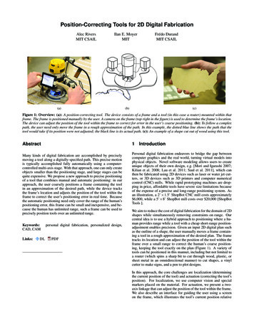
to the plan. We show an example of a device (Figure 1), measuringroughly 13” x 10” x 9”, that uses our approach and can be fitted witha router or a vinyl cutter, and show results that can be achieved withthese tools when they are positioned with our computer-augmentedapproach.2Related WorkRecent work on personal digital fabrication has yielded interfaces that integrate fabrication considerations with design, allowing fabrication-conscious design of a variety of material and object types such as plush toys [Mori and Igarashi 2007], chairs [Saulet al. 2011], furniture [Lau et al. 2011], shapes made out of a singlefolded piece of material [Kilian et al. 2008], and paneled buildings[Eigensatz et al. 2010]. Other papers explore how to generate designs with desired physical properties, such as deformation characteristics [Bickel et al. 2010], appearance under directed illumination[Alexa and Matusik 2010], and subsurface scattering [Dong et al.2010; Hašan et al. 2010].When it comes to fabricating objects from these designs, the mostwidely used devices are 3D printers, laser cutters, and CNC millingmachines. Recently, a variety of efforts growing out of the DIYcommunity have sought to reduce the cost of 3D printers [MakerBot Industries ; Drumm 2011; Sells et al. 2009] and CNC mills[Hokanson and Reilly ; Kelly ]. These projects typically providerelatively cheap kits for entry-level devices. However, as with professional models, positioning is done with a multi-axis stage, andthe trade-off between cost and range remains.Our computer-augmented positioning approach removes the limitation on range of traditional gantry-based positioning technologies. To do so, it relies on accurately detecting the position of theframe in real time. A variety of approaches to real-time localizationhave been employed over the years, from global-scale GPS [Getting1993] to local-scale systems based on radio and ultrasonic signals[Priyantha et al. 2000]; an overview is given in a survey by Welchand Foxlin [2002].Our approach to localization is based on computer vision. Computer vision has been widely used for position tracking in the context of motion capture (see Moeslund et al. [2006] for a survey).These setups typically use stationary cameras tracking a movingobject, though recently Shiratori et al. [2011] proposed a systemin which cameras are placed on the human and track the environment. In our approach, the camera is on the tool and tracks the material over which it moves, first stitching frames together to makea map of the material (see Zitova and Flusser [2003] and Szeliski[2006] for surveys of image registration and stitching techniques)and then using that map to perform localization. This approach hasbeen used before, with some differences, in a recent new peripheral,LG’s LSM-100 scanner mouse [LG ; Zahnert et al. 2010], which isa mouse that can scan a document it is passed over. Our implementation differs from theirs in that we use only a camera (no opticalmice), capture a wider area of the material in each frame, and usehigh-contrast markers placed on the material to allow capture ofuntextured materials.Computer vision has previously been applied to CNC manufacturing, for example to monitor for mistakes [Al-Kindi et al. 1993], orto precisely align a tool path to a piece of material [Techno CNCRouter Systems ]. These approaches, however, do not re-imaginethe fundamental approach or form factor of a table-based, fullyautomatically-positioned CNC device. A hybrid approach has beentaken in the case of computer-assisted surgical devices [Kragic et al.2005; Mako Surgical ], for example by using a robot to recreate amanual tool motion at a smaller scale for microsurgery. However,the motivation in these cases is to “take advantage of robotic speedFigure 2: Map: A scanned map with a plan registered to it. Thered dotted line indicates a path that a user could conceivably followto cut out the shape.and precision, but avoid the difficulties of full autonomy by retaining the human ‘in the loop’ for essential decision making and/orphysical guidance” [Kragic et al. 2005]. By comparison, our goalis to leverage the human’s mechanical range, rather than decisionmaking power or guidance, to enable a new form factor and approach to a task that is currently fully automated.3LocalizationTo keep the tool on the plan as closely as possible, the tool mustdetect its current position accurately, robustly, and with low latency.We considered a variety of localization systems, eventually settlingon a simple computer vision-based approach, in which a camera onthe frame of the device tracks high-contrast markers placed in anarbitrary pattern on the material. A map of the material (Figure 2)is first built by passing the device back and forth over the materialto be cut; then, images from the camera are compared to this mapto determine the device’s location. This approach was chosen for avariety of reasons: it can achieve very high accuracy; it always remains calibrated to the material, as the markers are on the materialitself (as opposed to external beacons, which can become uncalibrated); it does not require excessive setup; the hardware requiredis relatively inexpensive; and it can be implemented using standardcomputer vision techniques. Building the map is fast and easy.We considered using the camera to track just motion, as in an optical mouse, but this approach would be subject to drift. An alternative would be to draw the plan on the material itself, e.g. with apencil, and then track that, but that would require additional workon the part of the user and could introduce error.3.1High-contrast markersWe leverage specially-printed tape marked with high-contrast patterns to make it possible to track materials that have no visual features of their own (such as sheet metal or plastic) and to increaserobustness under varying lighting conditions. This tape is appliedbefore map-making, in any pattern so long as some tape is visiblefrom every position that the device will move to, and can be removed when the job is complete. The tape consists of many QuickResponse (QR) code-like markers [Denso-Wave Incorporated ] ina row, each consisting of an easily-detectable box-within-box pat-
tern we call an “anchor” and a 2D barcode that associates a uniquenumber with the anchor (see Figure 3). As long as four of thesemarkers are visible at any time (which is typically the case even ifonly a single piece of tape is visible), the device is able to locateitself. The redundancy of the markers means that it does not matterif some are occluded (e.g. by sawdust) or obliterated by the toolitself. Note that these markers function just as features – their positions are not assumed before mapping, and they need not be laidout in any specific pattern.Figure 3: Markers: A sequence of markers, with values 1000 to1006, such as would be printed on a strip of tape. In our current implementation, markers are printed at a size of roughly 0.8” 0.4”.This is small relative to the area of the material the camera can seeat once (roughly 8” 6”).3.2Image processingThe core operations used during locating and building a map aredetecting markers in an image and registering one set of markersonto another.To detect markers, the frame is first binarizedusing the Otsu method [1979], and then rectified to a top-down orthographic view based on a one-time calibration of the camera relative to the flat plane on which the tool sits. Anchors are extracted using a standard approach to QR code reading: first, horizontal scanlines are searched for runs of alternating pixel colors matching theratio of 1:1:3:1:1, as will always be found at an anchor. Locationsthat match this pattern are checked for the same pattern vertically.Locations that match horizontally and vertically are floodfilled toconfirm the box-within-box pattern. Once anchors have been extracted, each anchor is experimentally matched with the nearestanchor, and the area in between is parsed as a barcode. Barcodeorientation is disambiguated by having the first bit of the 2D barcode always be 1 and the last bit always be 0. If the parsed barcodedoes not match this pattern, the next-nearest anchor is tried. If neither matches, the anchor is discarded. If the pattern is matched, thebarcode’s value is associated with the first anchor and that anchor’sposition is added to the list of detected markers.Detecting markersTo match two sets of markers, wefind all pairs of two markers, one from each set, that share the sameID. If there are at least four such pairs, we run RANSAC [Fischlerand Bowles, 1981] to find the Euclidean transformation that mapsthe positions of the pairs’ markers in the first set to the corresponding positions in the second set, with a tolerance of 5 millimeters.While only two pairs are sufficient to determine a Euclidean transformation, we set the minimum number of inliers to four to preventfalse positives. The resulting least-squares transformation matrixestablishes a relative position constraint between the sets.Matching sets of markers3.3Building a mapMapping is done by stitching together video frames into a 2D mosaic (Figure 2) as the user passes the device back and forth overthe material. To reduce memory loads, we retain only frames thatoverlap with the previously retained frame by less than 75%, ascomputed after determining the frame’s position relative to all otherframes as as described below.We use a simple method to stitch images together. Each frame’scurrent position and orientation in the map is expressed as a 3 3transformation matrix. The first frame is assigned the identity matrix. When a new frame is received, a match is attempted with allprevious frames. Every successful match generates one relative position constraint, also expressed as a 3 3 matrix. The new frame’stransformation matrix is obtained by multiplying each matchedframe’s transformation matrix with the corresponding
CAD, CAM Links: DL PDF 1 Introduction Personal digital fabrication endeavors to bridge the gap between computer graphics and the real world, turning virtual models into physical objects. Novel software modeling allows users to create unique objects of their own design, e.g. [Mori and Igarashi 2007; Kilian et al. 2008;Lau et al. 2011;Saul et al. 2011], which can then be fabricated using 2D .