Transcription
The US Particle Accelerator SchoolMaterials, Fabrication Techniques, and JointDesignsLou BertoliniLawrence Livermore National LaboratoryJune 10-14, 2002USPAS June 2002Materials, Fabrication, Joint DesignPage 1
Stainless Steel High strength, moderate formability, excellent weldability. Can be extruded in simple shapes 304 SS, least expensive304L SS, most commonly used in vacuum, a little more expensive316 SS, most expensive, resistant to chemical attack, welds arenon-magnetic Wide variety of circular tubes and pipes available (seamless &welded) Outgassing rates can be decreased by employing good machiningtechniques, chemical cleaning and baking (up to 900oC) Thermal and electrical conductivity is poorUSPAS June 2002Materials, Fabrication, Joint DesignPage 2
Typical Physical Properties forStainless SteelsPropertyComposition:Melting Point (oC)Density (g/cc)Electrical Resistivity (W-cm)304304L316C 0.08%Cr 18-20%Mn 2%Fe 66-74%Ni 8-10.5%P 0.045%S 0.03%Si 1%C 0.03%Cr 18-20%Mn 2%Fe 66-74%Ni 8-12%P 0.045%S 0.03%Si 1%14271425138510838.08.08.08.927.2 x 10-57.2 x 10-57.4 x 10-51.71 x 10⁻⁶C 0.08%Cr 17%Mn 2%Mo 2.5%Fe 65%Ni 12%P 0.045%S 0.03%Si 1%Elect. Conduct. (% IACS*)Therm. Conduct. (W/m-K)OFE CuCu 100%10116.216.216.3391Coeff. Of Therm. Exp. (oC-1)17.2x10-617.2x10-616.0x10-617.5x10⁻⁶Mod. Of Elasticity (psi)28.6x10628.5x10628x10617x106USPAS June 2002Materials, Fabrication, Joint DesignPage 3
Typical Mechanical Properties forStainless SteelsProperty304304L316OFE CuTensile Strength (MPa)505564565338Tensile Strength (ksi)73.281.881.949.0Yield Strength (Mpa)21521025021730.536.331.570585555Modulus of Elasticity (Mpa)197197193115Modulus of Elasticity (ksi)28.628.628.016.7Yield Strength (ksi)31.2Elongation (%)Ref. www.matls.comUSPAS June 2002Materials, Fabrication, Joint DesignPage 4
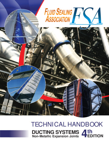
Tubing - Seamless and WeldedCleaner to start withand easier to cleanSeamless (extruded)USPAS June 2002Materials, Fabrication, Joint DesignPage 5Rolling can embed dirtin the surfaceWelded (rolled & welded)
PEP-II Straight SectionStainless Steel BeampipesCopper-plated SeamlessStainless Steel TubeStainless Steel Double-wall TubeUSPAS June 2002Materials, Fabrication, Joint DesignPage 6
Formed and Welded Stainless SteelChamber - Manpower IntensiveQ4 Chamber PartsQ5 ChamberUSPAS June 2002Materials, Fabrication, Joint DesignPage 7
Aluminum Moderate strength, good formability, easy to machine Can be extruded in complicated shapes 6061-T6 is the most common aluminum alloy for vacuum components 5083 is a good alloy for welding Aluminum is much cheaper to machine than stainless steel(2x to 3x cheaper) Special care must be taken in the design of welds and the techniquesused due to higher thermal conductivity and thermal expansion (30% SS) Surface anodizing degrades outgassing characteristics, but improveschemical resistanceUSPAS June 2002Materials, Fabrication, Joint DesignPage 8
Typical Mechanical Propertiesfor AluminumProperty1100-05083-H34 6061-T6OFE CuTensile Strength (MPa)165345310338Tensile Strength (ksi)23.950.045.049.0Yield Strength (Mpa)150280275217Yield Strength 16.7Elongation (%)Modulus of Elasticity (Mpa)Modulus of Elasticity (ksi)Ref. www.matls.comUSPAS June 2002Materials, Fabrication, Joint DesignPage 9
Typical Physical Properties for AluminumPropertyComposition:1100-0Al 99%Cu 0.05-0.2%Mn 0.05%Si Fe 0.95%Zn 0.1%5083-H346061-T6Al 94.8%Cu 0.1%Cr 0.05-0.25%Mg 4-4.9%Mn 0.4-1%Fe 0.4%Si 0.4%Ti 0.15%Zn 0.25%Al 98%Cu 0.15-0.4%Cr 0.04-0.35%Mg 0.8-1.2%Mn 0.15%Fe 0.7%Si 0.4-0.8%Ti 0.15%Zn 0.25%OFE CuCu 100%Melting Point (oC)6435915821083Density (g/cc)2.712.662.78.92Electrical Resistivity (W-cm)3x10-65.9x10-63x10-61.7x10-6Heat Capacity 10-625.2x10-617.5x10⁻⁶Therm. Conduct. (W/m-K)Coeff. Of Therm. Exp. (oC-1)Ref. www.matls.comUSPAS June 2002Materials, Fabrication, Joint DesignPage 10
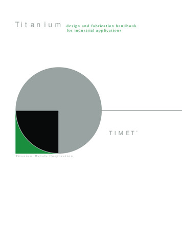
Aluminum Beam Pipe SpoolAl/SS Bi-metallicConflat FlangeGage Port w/ CurrentReturn BarsUSPAS June 2002Materials, Fabrication, Joint DesignPage 11Aluminum Tube
Machined Aluminum Vacuum ChamberUSPAS June 2002Materials, Fabrication, Joint DesignPage 12
Aluminum ExtrusionsUSPAS June 2002Materials, Fabrication, Joint DesignPage 13
Copper Typical copper alloys are C10100, C26800, C61400,C17200 Low-to-moderate strength, good formability Excellent electrical and thermal characteristics Difficult to weld (e-beam welding is best) May be joined by welding, brazing, and soldering Good outgassing characteristics, rates can be decreased byfollowing good machining techniques, chemical and baking( 200 C)USPAS June 2002Materials, Fabrication, Joint DesignPage 14
Copper ExtrusionsCooling BarExtrusionScreen ExtrusionUSPAS June 2002Materials, Fabrication, Joint DesignPage 15“Dipole” ChamberExtrusion
Machined Copper Chamber(PEP-II Wiggler Vacuum Chamber)USPAS June 2002Materials, Fabrication, Joint DesignPage 16 25 meters ofmachined copperchamber (5 – 5 metersections) 410 kWatts ofsynchrotron radiationpower absorbed Water coolingpassages areexternally machinedand e-beam weldedclosed 1-1/2 years tofabricate
Machined Copper Chamber (SPEAR3)USPAS June 2002Materials, Fabrication, Joint DesignPage 17
PEP-II HER High Power SynchrotronRadiation Dump ChamberUSPAS June 2002Materials, Fabrication, Joint DesignPage 18
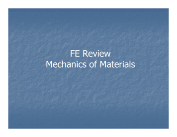
Machined Copper Chamber(PEP-II RF Cavities)USPAS June 2002Materials, Fabrication, Joint DesignPage 19 26 cavities 4M total fabrication cost Integral cooling channels withelectroformed cover 5 axis machining e-beam welded 17 separate manufacturing steps
GlidcopGlidcopGlidcop isis purepure coppercopper withwith AlAl22OO33 disperseddispersed throughout.throughout. High strength, moderate formability, poorweldability.Available in sheets, plate, wire, and extruded rounds.Maintains good mechanical strength after brazing.Outgassng rates are similar to pure copper.Thermal and electrical properties are good.Grade DesignationsCopperAl2O3UNSSCM Metal Prod.Wt %Vol %Wt %Vol %C15715Glidcop AL-1599.799.30.30.7C15725Glidcop AL-259.598.80.51.2C15760Glidcop AL-6098.997.31.12.7USPAS June 2002Materials, Fabrication, Joint DesignPage 20
Glidcop Physical PropertiesPropertyC15715C15725C15760OFE CuMelting Point (oC)1083108310831083Density (lb/in3)0.3210.3200.3180.323Electrical Resistivity (W)11.1911.91Elect. Conduct. (% IACS*)928778101Therm. Conduct. x10-6Coeff. Of Therm. Exp. (oC-1)Mod. Of Elasticity (psi)19x10619x106* International Annealed copper StandardUSPAS June 2002Materials, Fabrication, Joint DesignPage 2113.2919x10610.2019x106
WeldingWeldingWelding isis thethe processprocess wherewhere twotwo materialsmaterials areare joinedjoined byby fusionfusion Welding is the most common method for joining metals invacuum systems.Inert gas welding is the most common type of welding(TIG, MIG).Joint design is critical from vacuum, metallurgical anddistortion standpoints.Cleanliness is essential.Other welding processes to consider are electron beamand laser welding.USPAS June 2002Materials, Fabrication, Joint DesignPage 22
Welding Aluminum Low melting point, relatively high thermal conductivity, and highrate of thermal expansion make welding aluminum moreproblematic than stainless steel. Aluminum requires:1. High welding speeds (higher current densities)2. Good material purity and cleanliness3. Good joint design Aluminum welds have a tendency to crack from excessiveshrinkage stresses due to their high rate of thermalcontraction.USPAS June 2002Materials, Fabrication, Joint DesignPage 23
Welding Copper The high thermal conductivity of copper makes welding difficult.Heating causes the copper to recrystalize forming large grainsize and annealing. Distortion is also a big problem. Copper requires:1. Very high welding speeds2. Excellent material purity (OFE copper) and cleanliness.3. Good joint design Electron beam welding is an excellent process for weldingcopper.USPAS June 2002Materials, Fabrication, Joint DesignPage 24
Electron Beam Welding (EBW) EBW provides extremely high energy density in its focusedbeam producing deep, narrow welds. This rapid welding process minimizes distortion and the heataffected zone. A disadvantage of EBW is that the process takes placeunder vacuum (P 10-4 Torr):— Extensive fixturing required— High cost— Complexity— Welds are not cleanableUSPAS June 2002Materials, Fabrication, Joint DesignPage 25
Copper chambers ready for electronbeam weldingRF CavityUSPAS June 2002Materials, Fabrication, Joint DesignPage 26HER Quadrupole Chamber
SLAC Electron Beam WelderUSPAS June 2002Materials, Fabrication, Joint DesignPage 27
SolderingSolderingSoldering isis thethe processprocess wherewhere materialsmaterials areare joinedjoined togethertogetherbyby thethe flowflow ofof aa “filler“filler metal”metal” throughthrough capillarycapillary action.action. Soldering is differentiated from brazing primarily by the meltingtemperature of the filler metals. Solder alloys melt below 450 C. All soft solders are unacceptable for UHV systems because:- They contain Pb, Sn, Zr, Bi, Zn (vapor pressures are too high)- System bake-out temperatures typically exceed alloy meltingpoints. Most silver solders are unacceptable.USPAS June 2002Materials, Fabrication, Joint DesignPage 28
BrazingBrazingBrazing isis thethe processprocess wherewhere twotwo dissimilardissimilar materialsmaterials areare joinedjoinedtogethertogether byby thethe flowflow ofof aa “filler“filler metal”metal” throughthrough capillarycapillary action.action. There are several different brazing processes:1. Torch2. Furnace3. Induction4. Dip5. ResistanceBrazing can be used to join many dissimilar metals. The notableexceptions are aluminum and magnesium.Cleanliness is important in brazing. Cleanliness is maintained byuse of a flux or by controlling the atmosphere (vacuum or H2).USPAS June 2002Materials, Fabrication, Joint DesignPage 29
Brazing (cont.) Filler metals come in the form of wire, foils, or paste. Filler metals are selected to have melting points below thatof the base metal. Multiple braze steps are possible by choosing alloys ofdiffering melting points and proceeding sequentially fromhighest to lowest temperature. Braze joints require tight tolerances for a good fit(0.002” to 0.004”).USPAS June 2002Materials, Fabrication, Joint DesignPage 30
Typical Braze Alloys for UHV ComponentsAlloyBrazingTemperatureCompositionBAu -2890oC80% Au, 20% CuAu-CuNi925oC81.5% Au, 16.5% Cu, 2%NiBAu -4950oC82% Au, 18% Ni50/50Au-Cu35/65Au-Cu970oC50% Au, 50% Cu1010oC35% Au, 65% CuTime @ Temperature: 2-20 minutesUSPAS June 2002Materials, Fabrication, Joint DesignPage 31
There are a variety of metal sealsavailable for vacuum systems Copper (Conflats, wire, VATSEALS) Indium Foil or Wire Aluminum Wire Tin Wire or Foil Gold/Silver WireUSPAS June 2002Materials, Fabrication, Joint DesignPage 32
Conflat Flanges Vacuum rated to 1 x 10-13 Torr Temperature rated to 450 C Typical size range: 1-1/3”-16-1/2” od Flanges come in a variety ofconfigurationsrotatable- non-rotatable- tapped or clearance bolt holes- double-sided- Flanges are genderlessUSPAS June 2002Materials, Fabrication, Joint DesignPage 33
Conflat Flange DesignationsUSPAS June 2002Materials, Fabrication, Joint DesignPage 34
Wire Seal Flanges Vacuum rated to 1 x 10-13 Torr Temperature rated to 450 C Typical size range: 10” - 20” od Warning – male and female flangesUSPAS June 2002Materials, Fabrication, Joint DesignPage 35
PEP-II Wiggler Vacuum ChamberWelded FlangesWeld JointStructural JointUSPAS June 2002Materials, Fabrication, Joint DesignPage 36
PEP-II LER Arc Magnet Chamber TinSeal FlangesAluminum Raised-FaceFlange with 0.010”thick Tin-SealBellville WashersUSPAS June 2002Materials, Fabrication, Joint DesignPage 37
ANSI ASA Flanges Flanges come with either aflat-face or with an o-ringgroove. Vacuum rated to 1 x 10⁻⁸ Torr(better suited to 1 x 10⁻⁶ Torr) Temperature rating isdependent on which elastomero-ring is used (usually 150 C) Typical size range: 1” to 12”dia.USPAS June 2002Materials, Fabrication, Joint DesignPage 38
ISO Flanges Vacuum rated to 1 x 10⁻⁸ Torr(better suited to 1 x 10⁻⁶ Torr) Economical, re-usable flanges Elastomer gasket seal Temperature rated to 150 C Flanges come in a variety offastening styles:-Kwik-flangeRotatableNon-rotatableDouble claw clampBanded clampsUSPAS June 2002Materials, Fabrication, Joint DesignPage 39
VATSEAL FlangesSilverplated copper Metal seal, bakeable to300oC Custom sizes and shapes Radiation resistant UHV compatible Accelerator option - RFcontact between flangesUSPAS June 2002Materials, Fabrication, Joint DesignPage 40
Example of a VATSEAL Flange GasketUSPAS June 2002Materials, Fabrication, Joint DesignPage 41
Explosion Bonding allows for joining a variety ofmetals Plates Are Spaced AboveEach Other with AmmoniumNitrate Explosives AboveA Point Source ProgressiveCharge is Detonated andthe Plates Accelerated toContactAn Ion Plasma Jet isFormed at the ContactPoint Stripping Oxides andContaminates from theMetal SurfacesExtreme pressures atImpact and Ultra CleanSurfacesUSPAS June 2002Materials, Fabrication, Joint DesignPage 42Explosive Bonding EventStainlessFlyer PlateExplosiveMetal PlasmaAluminum Base Plate Dissimilar Atoms BondedTogetherMetallurgical Bond is made
Explosion Bonding Materials MatrixAtlas Technologies Bonding MatrixAluminumAL. AlloyChromiumCopperCU dbenumMoly. AlloyNickel, (Invar)NiobiumPlatinumRheniumSilverSteel, & AlloysSteel, MildStainless iumUSPAS June 2002Materials, Fabrication, Joint DesignPage 43Zirconium9 10 11 12 13 14 15 16 17 18 19 20 21 22 23 24 25 26 27 28 9Bonding CapabilityFlange Metal ainless SteelSteel, MildSteel, & AlloysSilverRheniumPlatinum8NiobiumHafnium7Nickel, (Invar)Gold6Moly. AlloyGlidCop5MolydbenumCU Alloy4MagnesiumCopper3LeadChromium2IronAL. Alloy1IndiumAluminumCopy Right Atlas Technologies January 1998Beam Stop, Absorber MaterialsSuper-conducting Flange Materials
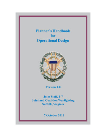
SS/AL Bond InterfacePatent# 5836623AL/SS Bond Interface StainlessStainlessCopperTitaniumAluminum USPAS June 2002Materials, Fabrication, Joint DesignPage 44Diffusion Inhibiting LayersCopper and TitaniumInterlayerEnables Bonding AL/SSVacuum: 1x10⁻¹⁰cc He/SecThermal:Peak 500C at weld up0-250C OperationalMechanicalTensile 38,000 Psi,Shear 30,000 Psi
Flange Production RecipePatent # 5836623Progressive ExplosionNon Bond Areas1.Bond AL Plate to Ti SheetBond SS Plate to Cu Sheet2.Bond AL/Ti Plate to SS/CuPlate3.Determine Non-Bond Areasof the SS/Cu/Ti/Al Plate4.Water Cut Discs From thePlate5.Machine Flanges from DiscsAtlas FlangesDetonatorUSPAS June 2002Materials, Fabrication, Joint DesignPage 45
Different applications for bi-metallic jointsAtlas Technologies305-B Glen Cove RoadPort Townsend, WA 98368Ph: 360-385-3123, Fax 360-379-5220atlas@olympus.net www.atlasbimetal.comUSPAS June 2002Materials, Fabrication, Joint DesignPage 46
Materials, Fabrication, Joint Design Page 22 Welding Welding is the most common method for joining metals in vacuum systems. Inert gas welding is the most common type of welding (TIG, MIG). Joint design is critical from vacuum, metallurgical and distortion standpoints. Cleanliness is ess