Transcription
T i ta n i u mdesign and fabrication handbookfor industrial applicationsTIMETTitanium Metals Corporation
Alloyse xpertiseserviceinventoryTitanium MetalsCorporationProductsT h e w o r l d ’scomplete titanium resourceTIMET 40 YEAR WARRANTYIn most power plant surface condenser tubing, tubesheet and service water pipe applications, TIMET CODEWELD Tubing and CODEROLL Sheet, Strip and Plate can be covered by written warranties against failure by corrosion fora period of 40 years.For additional information and copies of these warranties, please contact any of the TIMET locations shown on theback cover of this brochure.The data and other information contained herein are derived from a variety of sources which TIMET believes are reliable.Because it is not possible to anticipate specific uses and operating conditions, TIMET urges you to consult with ourtechnical service personnel on your particular applications. A copy of TIMET’s warranty is available on request.TIMET , TIMETAL , CODEROLL and CODEWELD are registered trademarks of Titanium Metals Corporation.
CONTENTSIntroduction . 1Designing with Titanium . 2Chemical CompositionsProduct Forms Available/ASTM SpecificationsDesign Stresses (ASME) . . . . . . . . . . . . . . . . . . . . . . . . . . . . . . . . . . . . . . . . . . . . . . . . . . . . . . . . . . . . 3Low Temperatures . . . . . . . . . . . . . . . . . . . . . . . . . . . . . . . . . . . . . . . . . . . . . . . . . . . . . . . . . . . . . . . . 5Welded Tubing – Safe Working Pressures . . . . . . . . . . . . . . . . . . . . . . . . . . . . . . . . . . . . . . . . . . . . . . 7Tube Vibration and RigidityHeat Transfer . . . . . . . . . . . . . . . . . . . . . . . . . . . . . . . . . . . . . . . . . . . . . . . . . . . . . . . . . . . . . . . . . . . . 8Solid, Clad or Lined Construction. . . . . . . . . . . . . . . . . . . . . . . . . . . . . . . . . . . . . . . . . . . . . . . . . . . . 10Tubesheet Materials/Galvanic Considerations . . . . . . . . . . . . . . . . . . . . . . . . . . . . . . . . . . . . . . . . . . 11F a b r i c a t i n g T i t a n i u m . . . . . . . . . . . . . . . . . . . . . . . . . . . . . . . . . . . . . . . . . . . . . . . . . . . . . . 13Work AreaShearingFlame CuttingSawingHand Abrasive GrindingMachining . . . . . . . . . . . . . . . . . . . . . . . . . . . . . . . . . . . . . . . . . . . . . . . . . . . . . . . . . . . . . . . . . . . . . 14Forming . . . . . . . . . . . . . . . . . . . . . . . . . . . . . . . . . . . . . . . . . . . . . . . . . . . . . . . . . . . . . . . . . . . . . . . 23Roller Expansion . . . . . . . . . . . . . . . . . . . . . . . . . . . . . . . . . . . . . . . . . . . . . . . . . . . . . . . . . . . . . . . . 25Welding . . . . . . . . . . . . . . . . . . . . . . . . . . . . . . . . . . . . . . . . . . . . . . . . . . . . . . . . . . . . . . . . . . . . . . . 26Welding Environment . . . . . . . . . . . . . . . . . . . . . . . . . . . . . . . . . . . . . . . . . . . . . . . . . . . . . . . . . 27ProcessesShieldingJoint Preparation . . . . . . . . . . . . . . . . . . . . . . . . . . . . . . . . . . . . . . . . . . . . . . . . . . . . . . . . . . . . . 29CleaningSelection Weld Wire (filler metal) . . . . . . . . . . . . . . . . . . . . . . . . . . . . . . . . . . . . . . . . . . . . . . . . 30Welding ParametersTechnique and ProceduresEvaluating Weld Quality . . . . . . . . . . . . . . . . . . . . . . . . . . . . . . . . . . . . . . . . . . . . . . . . . . . . . . . 31Resistance Welds . . . . . . . . . . . . . . . . . . . . . . . . . . . . . . . . . . . . . . . . . . . . . . . . . . . . . . . . . . . . . 32Brazing Titanium . . . . . . . . . . . . . . . . . . . . . . . . . . . . . . . . . . . . . . . . . . . . . . . . . . . . . . . . . . . . . 33Heat Treating TitaniumS u r f a c e T r e a t m e n t s . . . . . . . . . . . . . . . . . . . . . . . . . . . . . . . . . . . . . . . . . . . . . . . . . . . . . . . . . . 34M a i n t e n a n c e o f T i t a n i u m E q u i p m e n t . . . . . . . . . . . . . . . . . . . . . . . . . . . . . . . . . . . . 35
INTRODUCTIONTitanium offers an excellent combinationof mechanical properties and corrosionresistance. These features, coupled withavailability of product forms and ease offabrication, have led to extensive use oftitanium and its alloys in chemical processequipment. Titanium is now a standardmaterial of construction for manychemical processes and equipment, andsystems are being assembled by a varietyof fabricators on a routine basis for use inmany other industries.Successful utilization requires carefulconsideration of titanium’s uniquecharacteristics at the design stage aswell as during fabrication. Factors suchas titanium’s high strength to weightratio, low elastic modulus, corrosion anderosion resistance, its tendency towardgalling, and its reactivity at hightemperatures must be considered inorder to optimize designs in titanium.It is generally best to start fresh withtitanium’s properties in mind instead ofattempting to simply substitute titaniumfor other materials previously used.Fabricators who routinely work withtitanium will be helpful in optimizingdesign of titanium equipment.The following sections address someaspects of the design, fabrication andmaintenance of titanium equipment.Design of titanium equipment hasfollowed traditional standards establishedfor other materials of construction. ASTMmill product specifications, TEMA andASME Code standards are followed infabrication. Standard product forms arereadily available.Throughout this publication TIMETtitanium alloys are identified using theTIMETAL format. This system identifiestitanium alloys and products whichhave been under TIMET control duringall phases of production, from orethrough mill product; for example,Ti-50A (ASTM Gr. 2) is referred toas TIMETAL 50A.1
DESIGNINGWITHTITANIUMexchanger tubing, therefore, is normallyless than would be required forother materials.some design features. For example,the ductility of an alloy limits theminimum bend radius which is feasiblefor sheet, plate or tubing. It will also beadvantageous to incorporate standardproduct forms into designs utilizingtitanium. The excellent corrosionresistance of titanium often permits azero corrosion allowance to be specified.Wall thickness for vessels and heatThe successful design of titaniumequipment begins with considerationof the environment to which theequipment is to be exposed. Thecorrodents present and maximumoperating temperature (under upsetconditions, possibly) will dictate whichTIMET alloy should be selected. Thephysical and mechanical properties ofthe alloy selected may, in turn, dictateChemical CompositionThe chemical compositions of titaniumalloys used in industrial applications aregiven in Table 1.Ta b l e 1Nominal Chemic al CompositionTIMETAL35A35A .05Pd135A .15Pd50A50A .05Pd150A .15Pd65ACode 123-2.53-2.5 .05Pd16-46-4 ELI21S21S .05Pd3864438644 6-.9.2-.4————————— 14.0-16.0— 400.400.400.400.400.400.400.40These Grades were included into the ASTM Specifications for titanium mill products in 1992, but have not been included at the time of publication in the ASMEBoiler Code Specifications. For the reader’s information, the mechanical properties of the palladium (Pd) modified Grades are the same as the base Grades.The only difference of note is the improved corrosion resistance of the Pd modified Grades.Ta b l e 2T i ta n i um P r o d u c t F o r m s a n d A S TM / A S M E B o i l e r C o d e S p e c i f i c at i o n sAlloys Covered*Product FormsStrip, Sheet, PlateWelded PipeWelded TubingBars and BilletsWelded ecs35AGr. 150AGr. 265AGr. B381nnnnnnnnnnnn6-4Gr. 550A .15PdGr. 735A .05PdGr. 17**Code 12Gr. 123-2.5Gr. nnnn¶¶¶¶¶¶n¶235A .15PdGr. 11¶nn¶nn¶¶¶¶¶ ¶¶ ¶¶¶ Alloy covered by specifications and product forms available from TIMET.Alloy not covered by specification.50A .05PdGr. 16** Alloy covered by specification but product forms not available from TIMET.¶75AGr. 4** In process of ASME approval for SB specs.
Product Forms Available/ASTM SpecificationsThe titanium product forms availableand the ASTM specifications which coverthese are given in Table 2. As noted,TIMET is a supplier of strip, sheet, plate,bars, billets and castings. Tubing issupplied through VALTIMET, a jointventure company formed betweenVallourec and TIMET. TIMET’sCODEROLL program for sheet and plateprovides standard stock sizes for ASMEBoiler Code applications which reducecosts and increase design efficiencies.Likewise, VALTIMET’s CODEWELDtubing is available in a variety of sizeswhich allow flexibility of design.Through its worldwide service centernetwork TIMET offers a full range oftitanium mill products, pipe, fasteners,fittings, weld wire and extrusions.Design StressesMaximum allowable stress values as setforth by the ASME Boiler and PressureVessel Code, Section VIII-Division 1(prior to 1995); Section II, Part D (since1995) are given in Table 3. These valuesTa b l e 3M a x i m u m A l l o wa b l e S t r e s s Va l u e s i n T e n s i o n f o rA n n e a l e d T i ta n i u m a n d T i ta n i u m A l l o y s , K S I *MaterialForm andSpec. T1WPT2WPT3WPT1WWPT2WWPT3WTIMETAL35A50A65A50A .15PdCode 123-2.535A50A65A50A .15PdCode 123-2.535A50A65A50A .15PdCode 123-2.535A50A65A50A .15PdCode 123-2.535A50A65A50A .15PdCode 123-2.535A50A65A50A .15PdCode 1235A50A65A50A .15PdCode 1250A65A35A50A65A35A50A65ASpecified Min. YieldTensile0.2%Strength 0.916.410.313.87.310.914.36.29.312.1For Metal Temperature Not Exceeding F ( C)250300350400450500(121)(149)(177) (204) .05.7———3.15.76.02.64.85.1Notes: (1) 85% joint efficiency has been used in determining the allowance stress values for welded pipe and tube [see UG-31(a)].(2) Filler metal shall not be used in the manufacture of welded tubing or pipe.Values in this table are smaller of 1/3 of the minimum yield strength or 1/4 of the specified tensile strength.*From Table UNF-23.4 ASME Boiler and Pressure Vessel Code, Section VIII-Division 1 (prior to 1995).From Table 1B, Section II, Part D, ASME Boiler and Pressure Vessel Code for Section VIII, Division 1 Service (since 1995).3
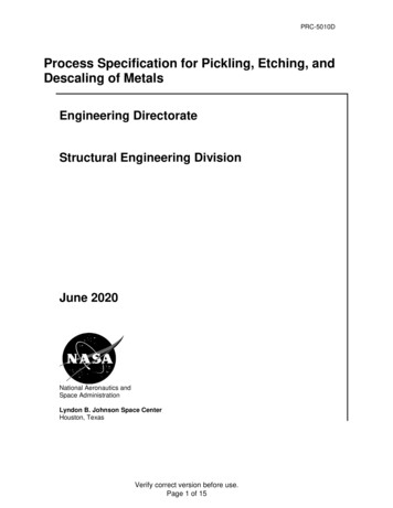
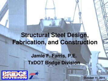
Ta b l e 4D e s i g n S t r e s s I n t e n s i t y Va l u e s i n T e n s i o n f o rA n n e a l e d T i ta n i u m a n d T i ta n i u m A l l o Y s , K S I *Spec.No.ASTMGradeTIMETALP-No.Plate, Sheet and StripSB-265135A250A365A750A .15PdPipe and TubingSB-337135ASB-338250ASeamless365A750A .15PdSB-337SB-338Welded1237Bar and BilletSB-3481237ForgingsSB-381F1F2F3F7Specified Min. YieldTensile0.2%Strength OffsetNotes100(38)150(66)200(93)For Metal Temperature Not Exceeding F ( 98.04.77.58.97.54.27.38.07.335A50A65A50A 7.66.43.66.26.86.235A50A65A50A .27.38.07.335A50A65A50A .27.38.07.3NOTES: (1) A quality factor of 0.85 has been applied in arriving at the design intensity values of this material.(2) Filler metal shall not be used in the manufacture of welded tubing or pipe.*From Table ANF-1.4 ASME Boiler and Pressure Vessel Code, Section VIII-Division 2 (prior to 1995).From Table 2B, Section II, Part D, ASTM Boiler and Pressure Vessel Code, for Section VIII, Division 2 Service (since 1995).FIGURE 1C h a rt f or de t e r m i n i n g s h e l l t h ic k n e s s of c y l i n dr ic a l a n d s p H e r ic a l v e s s e l s u n de re x t e r n a l p r e s s u r e w h e n c o n s t r u c t e d o f t i m e t a l 5 0 a ( g r a d e 2 ) u n a l l o y e d t i ta n i u m25,000G E N E R A L N O T E : S E E TA B L E N T F - 2 F O R TA B U L A R VA L U E SUP TO 100 F (38 C)20,000200 F (93 C)18,00016,00014,000400 F (204 C)12,0009,0008,0007,0006,0005,000EEEE 00.00001234567 8 9.0001234567 8 9.001FA C T O R A234567 8 92.01Pa 4B———3(D /t) 3and456Pa 7 8 9.12AE———3(D /t) Instructions for calculating A and B and for using this chart are given in ASME Boiler and Pressure Vessel Code Section VIII Division 1 Part UG paragraph UG-28.From Fig. 5-UNF-28.28 Appendix 5 Section VIII, Division 1 ASME Boiler and Pressure Vessel Code (prior to 1995).From Fig. NFT-2, Section II, Part D ASME Boiler and Pressure Vessel Code (since 1995).4FA C T O R B10,000600 F (316 C)
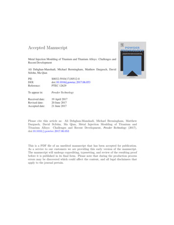
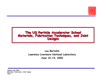
are obtained using the prescribed ASMEBoiler Code Procedure, i.e., the lesser ofone fourth of the ultimate tensilestrength or one third of the 2% offsetyield strength at each given temperature.Various product forms of annealedTIMETAL (ASTM Grade) alloys arecovered in this table. Design stressintensity values (for less severe service)for Section VIII-Division 2 constructionare given in Table 4. Figures 1 and 2 arecharts for determining shell thicknessof cylindrical and spherical vessels underexternal pressure when constructedof TIMETAL 50A (Gr. 2) and TIMETAL65A (Gr. 3), respectively, followingASME procedures.to be used down to -75 F (-59 C)provided the user is satisfied thatsuitable ductility is available at thedesign temperature. Notched andunnotched tensile tests are suggested byASME as means whereby the titaniumalloy can be judged to be suitable.L o w Te m p e r a t u r e sTitanium has excellent properties at lowtemperatures. Best ductility at very lowtemperatures is available from TIMETAL35A (Gr. 1) and TIMETAL 50A (Gr. 2).However, no marked drop in impactresistance is observed at subzerotemperatures in any of the titaniumalloys. Because of this, the ASME Boilerand Pressure Vessel Code allowsunalloyed titanium TIMETAL 35A (Gr. 1),TIMETAL 50A (Gr. 2), TIMETAL 65A(Gr. 3) and TIMETAL 50A .15Pd (Gr. 7)FIGURE 2C h a rt f or de t e r m i n i n g s h e l l t h ic k n e s s of c y l i n dr ic a l a n d s p H e r ic a l v e s s e l s u n de re x t e r n a l p r e s s u r e w h e n c o n s t r u c t e d o f t i m e t a l 6 5 a ( g r a d e 3 ) u n a l l o y e d t i ta n i u m30,000G E N E R A L N O T E : S E E TA B L E N T F - 1 F O R TA B U L A R VA L U E SUP TO 100 F (38 C)25,000200 F (93 C)20,00018,00016,00014,000400 F (204 C)10,000600 F (316 C)9,0008,000FA C T O R B12,0007,0006,000EEEE 00.00001234567 8 9.0001234567 8 9.001FA C T O R A234567 8 92.01Pa 4B———3(D /t) 34and56Pa 7 8 9.12AE———3(D /t) Instructions for calculating A and B and for using this chart are given in ASME Boiler and Pressure Vessel Code Section VIII Division 1 Part UG paragraph UG-28.From Fig. 5-UNF-28.22 Appendix 5 Section VIII, Division 1 ASME Boiler and Pressure Vessel Code (prior to 1995).From Fig. NFT-1, Section II, Part D ASME Boiler and Pressure Vessel Code (since 1995).5
Ta b l e 5Welded Tubing Safe External Working Pressure ( psi ) at 100 F (38 C)For Annealed TIMETAL 50A (ASTM Grade 2), TIMETAL 50A .15P d (ASTM Grade 7)and TIMETAL 50A .05P d (ASTM Grade 6613371557175320641"1.00Outside Diameter of 81133192273425551714857According to Part VG Paragraph VG-2B: (1) Calculate Do/t. (2) Obtain Factor A from Figure 5-VGO-28.0 Appendix 5, Section VIII, Division 1 ASME Boiler and Pressure Vessel Code (prior to1995), or from Figure G, Section II, Part D, ASME Boiler and Pressure Vessel Code (since 1995). (3) Obtain Factor B. Refer to Figure 1 (ASTM Grades 2, 7, 16*) or Figure 2 (ASTM Grade 3).4B4B(4) External Pressure Formula: Pa –––––––– assumes a seamless tube. For welded tube: Pa ––––––––– x .85[E .85]3 (Do/t)3 (Do/t)Note: Values in this table may not be exact as they were manually extracted*ASTM Grade 16 is in the process of ASME SB338 approval.from Figure 1 to determine factors A and B in the pressure formula.The safe internal working pressures are shown in Table 5A.Ta b l e 5 aWelded Tubing Safe Internal Working Pressure ( psi ) † At 100 F (38 C)For Annealed TIMETAL 50A (ASTM Grade 2), TIMETAL 50A .15P d (ASTM Grade 7)and TIMETAL 50A .05Pd (ASTM Grade 788951111613311501167319471"1.00Outside Diameter of 53013624235025646267258339601061where S Maximum allowable stress from the seamless tubing section of Table 3, psi; E 0.85 for welded tubing and 1 for seamless tubing;SEtcalculated from P ––––––––t Minimum tube wall thickness allowed (nominal – 10%), inches; and Ro 1/2 the tube outside diameter, inches.Ro – 0.4tIf maximum allowable stress (S) is chosen from the welded tubing section of Table 3, the 85%joint efficiency has already been applied to these values and the following formula 38177919721-3/4"1.75StP ––––––––Ro – 0.4t*ASTM Grade 16 is in the process of ASME SB338 approval.The safe external working pressures are shown in Table 7861951
W e l d e d Tu b i n g – S a f eWorking PressuresSafe external working pressures forannealed TIMETAL 50A (Gr. 2) weldedtubing of various diameters and wallthickness for temperatures up to 100 F(38 C) are given in Table 5. Themultiplying factors given in Table 6allow calculation of safe internalpressures for welded tubing for otheralloys and to temperatures as high as600 F (316 C). The data in Tables 5Aand 6 can be used to select theminimum wall thickness of weldedtubing required for internal pressureand temperature conditions anticipatedin heat exchanger service. Unlike manyother materials, a corrosion allowance isusually not required for titanium.This permits thinner-walled tubing tobe used than is generally practical withother materials.Tu b e V i b r a t i o n a n dRigidityTube vibration in a heat exchangeroccurs when shellside cross flow velocityis too high and baffle spacing is toodistant. Excessive tube vibration mayresult in fatigue failures at supportplates or in midspan collision damage.Titanium’s hardness and corrosionfatigue resistance act to minimizevibration damage, but its lower modulus(than steel or copper-nickel alloys)must be considered in design to keepdeflection within acceptable limits.Proper baffle design and spacing shouldbe incorporated into the designs of bothnew and retrofit titanium tube bundlesto avoid flow induced vibration. Acomparison of static deflections fortitanium tubing and other materials andthe reduction in baffle spacing requiredwhen using titanium tubes is shown inTable 7. The data illustrate that areduction in baffle space is more effectivethan an increase in wall thickness indecreasing deflection. Generally, ifvibration has not been a problem in a heatexchanger, retubing with titanium usingproper baffle spacing will eliminate flowinduced vibration as a potential problem.Ta b l e 6Multiplying Factors to Determine Safe Internal Working Pressuresof Annealed, Welded Titanium Tubing at Elevated Temperatures*TIMETAL35A50A50A .15Pd65ACode 12100 (38)127312For Metal Temperatures Not Exceeding, F ( C)250 (121) 300 (149) 350 (177) 400 (204) 450 (232)150 (66)200 36.672.8321.065.616.7441.000ASTM Grade500 (260)550 (288)600 536.456.480*Select safe working pressure (SWP) for TIMETAL 50A tubing of desired size and gauge from Table 5A. Then use multiplying factor from Table 6 above to determine SWP for desired alloy and temperature.Example: Determine SWP for TIMETAL Code 12 1"x .065" welded tubing at 350 F. From Table 5A, SWP for 1"x .065" TIMETAL 50A welded tubing at 100 F is 1304 psi. The multiplying factorfor TIMETAL Code 12 at 350 F from Table 6 above is 1.065. The SWP for TIMETAL Code 12 at 350 F is calculated as 1.065 x 1304 1389 psi.Ta b l e 7S u p p o rt P l at e S pa c i n g R e d u c t i o nMaterialO.D.Tube Size(Inches)Titanium3/4”70-30 Cu-Ni3/4”90-10 Cu-Ni3/4”Aluminum Bronzeand Admiralty BrassTitanium3/4”170-30 Cu-Ni190-10 Cu-Ni1Aluminum Bronzeand Admiralty Brass1% Spacing ReductionReplacement with Titanium0.035"0.049"20 BWG18 .0651613.97.47
H e a t Tr a n s f e rThe thermal conductivity of titanium isroughly 50% higher than 304 stainlesssteel as shown in Table 8. Thiscontributes to its excellent heattransfer properties.The overall heat transfer coefficient, U(Btu/hr.-ft 2- F), indicates the ability of asurface to transfer heat from onepermit high tube side velocities(minimizing rt), and be usable in thinnestsection (minimizing rm).flowing fluid on one side to another fluidon the opposite side. The inverse of thecoefficient, (1/U), can be considered tobe the total resistance to heat flowwhich, as indicated in Figure 3, is madeup of five component resistances: tubeside fluid, rt, tube-side fouling, rtf, tubemetal, rm, shell-side fouling, rsf, andshell-side fluid, rs. An ideal tube materialwill resist fouling (minimizing rtf and rsf),A zero corrosion allowance can oftenbe specified for titanium. This, coupledwith adequate strength, permitstitanium tubing to be used withunusually thin walls.Ta b l e 8T h e r m a l c o n d u c t i v i t y o f m e ta l s , B t u / h r . - f t.MaterialNaval BrassAdmiralty Brass90-10 Cu-Ni70-30 Cu-NiMonelTIMETAL 50ATIMETAL Code 12Type 304 SS100 F (38 C)7683482041501481042- F/in.200 F (93 C)300 F (149 C)400 F (204 C)500 F (260 C)600 F (316 961068504300204134130136,,,yy,,yy ,,, z ,,yy, y{,,yy,,yy,,yy ,,, z ,,yy, y{,,yy,,yy { FIGURE 3t o ta l r e s i s ta n c e o f h e at e x c h a n g e r t u b e sH E A T T R A N S F E R U x ( M E A N T E M P. D I F F. ) x ( E F F. T U B E A R E A )T E M P E R AT U R EGRADIENTTUBE5X,,,yyy,,yy,,,yyy,,yy,,,yyyT O TA LR E S I S TA N C ETUBE-SIDEFLUIDTUBE-SIDESCALETUBEM E TA L,,yySHELL-SIDESCALE1—– r t r t f r m r s f r sU8SHELLSHELL-SIDEFLUID
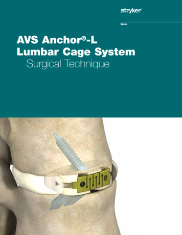
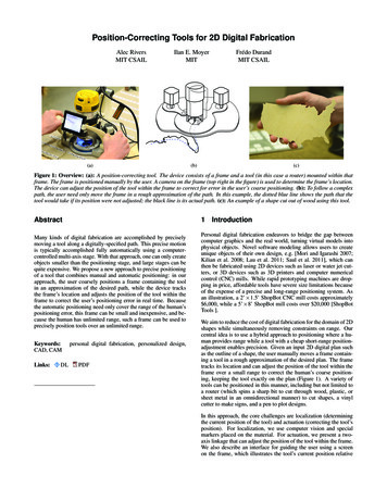
distillation and condensation fortitanium, as compared to other metals.The high resistance of titanium tocorrosion prevents buildup of corrosionproducts which rob other metals of heattransfer efficiency. Titanium’s hard,smooth surface also minimizes buildupof external fouling films and makescleaning and maintenance easier.Figure 4 shows the high rates ofThe excellent resistance of titanium toturbulence and erosion-corrosionpermits use of relatively high flow ratesof 18-22 ft./sec. in silt-laden seawateror even up to 100 ft./sec. in cleanseawater without damage to the passiveoxide film. Tests in 80 F (27 C) seawater for 60 days at 25 ft./sec. haveshown titanium’s corrosion-erosionresistance to be 80 times better thanthat of the next-best material, acopper-nickel alloy. Other tests in85 F (29 C) sea water for 60 days at27 ft./sec. proved titanium to be almost100 times better than stainless steel,the next-best material.FIGURE 4C o m p a r at i v e r at e s o f d i s t i l l at i o n a n d c o n d e n s at i o n1210T I TA N I U MTYPE 3161.6T I TA N I U M1.4HASTELLOY C1.2TYPE 3161.0TYPE 3040.80.60.4T I TA N I U M C O N D E N S E S :2 0 . 9 % M O R E T H A N T Y P E 3 0 4 S TA I N L E S S S T E E L1 6 % M O R E T H A N T Y P E 3 1 6 S TA I N L E S S S T E E L4.3% MORE THAN TYPE HASTELLOY CHASTELLOY C0.2TYPE 3040COPPER050100150200250MINUTESGLASS6R E L AT I V E R AT E S O F N I T R I C A C I D D I S T I L L AT I O NFROM A 70% NITRIC ACID SOLUTION1.81.6L I T E R S O F W AT E R D I S T I L L E DL I T E R S O F W AT E R D I S T I L L E D8LITERS OF NITRIC ACID DISTILLED1.8T I TA N I U M C O N D E N S E S :43.8% MORE THAN GLASS31.4% MORE THAN COPPER2 2 . 7 % M O R E T H A N T Y P E 3 0 4 S TA I N L E S S S T E E L15.0% MORE THAN HASTELLOY C1 0 . 8 % M O R E T H A N T Y P E 3 1 6 S TA I N L E S S S T E E L42TYPE 316T I TA N I U M1.4COPPERTYPE 3041.21.00.80.60.4T I TA N I U M C O N D E N S E S :3 3 % M O R E T H A N T Y P E 3 0 4 S TA I N L E S S S T E E L29.3% MORE THAN COPPER2 0 % M O R E T H A N T Y P E 3 1 6 S TA I N L E S S S T E E L0.200024681012141618HOURSR E L AT I V E R AT E S O F W AT E R D I S T I L L AT I O NU S I N G D E I O N I Z E D W AT E R200123456HOURSR E L AT I V E R AT E S O F W AT E R D I S T I L L AT I O NFROM A 3.5% SODIUM CHLORIDE SOLUTIONRates of distillation and condensation are high for titanium compared to other metal heat exchanger surfaces.9
inside 3/4” x 18 gauge tubes and steamwas condensing on the outside. Hadthin-walled titanium tubing been usedas is present practice, the heat transf
aspects of the design, fabrication and maintenance of titanium equipment. Design of titanium equipment has followed traditional standards established for other materials of construction. ASTM mill product specifications, TEMA and ASME Code standards are followed in fabrication. Standard