Transcription
OM Book.book Page 1 Wednesday, April 3, 2013 1:39 PMXPS 27Owner’s ManualComputer model: XPS 2720Regulatory model: W06CRegulatory type: W06C002
OM Book.book Page 2 Wednesday, April 3, 2013 1:39 PMNotes, Cautions, and WarningsNOTE: A NOTE indicates important information that helps you make betteruse of your computer.CAUTION: A CAUTION indicates potential damage to hardware or loss ofdata if instructions are not followed.WARNING: A WARNING indicates a potential for property damage,personal injury, or death. 2013 Dell Inc.Trademarks used in this text: Dell , the DELL logo, and XPS are trademarks of Dell Inc.;Microsoft and Windows are either trademarks or registered trademarks of MicrosoftCorporation in the United States and/or other countries; Blu-ray Disc is a trademark ownedby the Blu-ray Disc Association (BDA) and licensed for use on discs and players;Bluetooth is a registered trademark owned by Bluetooth SIG, Inc. and is used by Dell underlicense; Intel and Intel SpeedStep are registered trademarks of Intel Corporation in the U.S.and/or other countries.2013 - 04Rev. A00
OM Book.book Page 3 Wednesday, April 3, 2013 1:39 PMContents1Before You Begin . . . . . . . . . . . . . . . . . . . . . .Turn Off Your Computer and Connected Devices .Safety Instructions . . . . . . . . . . . . . . . . . . . . . .Recommended Tools . . . . . . . . . . . . . . . . . . . .111112. . . . . .13. . . . . . . . . . . . . . . . . . . .142After Working Inside Your Computer .3Technical Overview .Inside View of Your Computer .System-Board Components . .4561415. . . . . . . . . . . . . . .17. . . . . . . . . . . . . . . . . . . . . . . . . . . .17Replacing the Back Cover .Procedure18. . . . . . . . . . . . . . . . . . . . . . . . . . . .18Removing the Trim Cover . . . . . . . . . . . . . . .19. . . . . . . . . . . . . . . . . . . . . . . . . .1919. . . . . . . . . . . . . . . . . . . . . . . . . .Replacing the Trim CoverProcedure . . .Postrequisites .8. . . . . . . . . . . . . . . .20. . . . . . . . . . . . . . . . . . . . . . . . .2020. . . . . . . . . . . . . . . . . . . . . . . . .Removing the StandPrerequisites .Procedure . .9. . . . . . . . . . . . . . . . . . . . . . . . . . . .Prerequisites .Procedure . .7. . . . . . . . . . . . . .Removing the Back Cover .Procedure11. . . . . . . . . . . . . . . . . . . .21. . . . . . . . . . . . . . . . . . . . . . . . . .2121. . . . . . . . . . . . . . . . . . . . . . . . . .Replacing the Stand .Procedure . . .Postrequisites . . . . . . . . . . . . . . . . . . . .22. . . . . . . . . . . . . . . . . . . . . . . . . . . . . . . . . . . . . . . . . . . . . . . . .2222Contents 3
OM Book.book Page 4 Wednesday, April 3, 2013 1:39 PM10 Removing the Converter BoardPrerequisites .Procedure . . . . . . . . . . . .23. . . . . . . . . . . . . . . . . . . . . . . . . .2323. . . . . . . . . . . . . . . . . . . . . . . . . .11 Replacing the Converter BoardProcedure . . .Postrequisites . . . . . . . . . . .24. . . . . . . . . . . . . . . . . . . . . . . . .2424. . . . . . . . . . . . . . . . . . . . . . . . .12 Removing the Optical DrivePrerequisites .Procedure . . . . . . . . . . . . . . .25. . . . . . . . . . . . . . . . . . . . . . . . . .2525. . . . . . . . . . . . . . . . . . . . . . . . . .13 Replacing the Optical DriveProcedure . . .Postrequisites . . . . . . . . . . . . . .27. . . . . . . . . . . . . . . . . . . . . . . . .2727. . . . . . . . . . . . . . . . . . . . . . . . .14 Removing the Memory Module(s)Prerequisites .Procedure . . . . . . . . . .28. . . . . . . . . . . . . . . . . . . . . . . . . .2828. . . . . . . . . . . . . . . . . . . . . . . . . .15 Replacing the Memory Module(s).Procedure . . .Postrequisites . . . . . . . . .30. . . . . . . . . . . . . . . . . . . . . . . . .3030. . . . . . . . . . . . . . . . . . . . . . . . .16 Removing the System-Board Shield .Prerequisites .Procedure . . . . . . . .31. . . . . . . . . . . . . . . . . . . . . . . . . .3131. . . . . . . . . . . . . . . . . . . . . . . . . .17 Replacing the System-Board Shield .Procedure . . .Postrequisites . . . . . . .32. . . . . . . . . . . . . . . . . . . . . . . . .3232. . . . . . . . . . . . . . . . . . . . . . . . .18 Removing the Power-Supply Fan .Prerequisites .Procedure . . . . . . . . . .33. . . . . . . . . . . . . . . . . . . . . . . . . .3333. . . . . . . . . . . . . . . . . . . . . . . . . .19 Replacing the Power-Supply Fan .Procedure . . .Postrequisites .4 Contents. . . . . . . . .34. . . . . . . . . . . . . . . . . . . . . . . . .3434. . . . . . . . . . . . . . . . . . . . . . . . .
OM Book.book Page 5 Wednesday, April 3, 2013 1:39 PM20 Removing the Hard DrivePrerequisites .Procedure . . . . . . . . . . . . . . . . .35. . . . . . . . . . . . . . . . . . . . . . . . . .3535. . . . . . . . . . . . . . . . . . . . . . . . . .21 Replacing the Hard DriveProcedure . . .Postrequisites . . . . . . . . . . . . . . . .37. . . . . . . . . . . . . . . . . . . . . . . . .3737. . . . . . . . . . . . . . . . . . . . . . . . .22 Removing the Hard-Drive Cage .Prerequisites .Procedure . . . . . . . . . . .38. . . . . . . . . . . . . . . . . . . . . . . . . .3838. . . . . . . . . . . . . . . . . . . . . . . . . .23 Replacing the Hard-Drive CageProcedure . . .Postrequisites . . . . . . . . . . .39. . . . . . . . . . . . . . . . . . . . . . . . .3939. . . . . . . . . . . . . . . . . . . . . . . . .24 Removing the I/O PanelPrerequisites .Procedure . . . . . . . . . . . . . . . . . .40. . . . . . . . . . . . . . . . . . . . . . . . . .4040. . . . . . . . . . . . . . . . . . . . . . . . . .25 Replacing the I/O Panel.Procedure . . .Postrequisites . . . . . . . . . . . . . . . . .41. . . . . . . . . . . . . . . . . . . . . . . . .4141. . . . . . . . . . . . . . . . . . . . . . . . .26 Removing the Coin-Cell BatteryPrerequisites .Procedure . . . . . . . . . . .42. . . . . . . . . . . . . . . . . . . . . . . . . .4242. . . . . . . . . . . . . . . . . . . . . . . . . .27 Replacing the Coin-Cell Battery .Procedure . . .Postrequisites . . . . . . . . . .43. . . . . . . . . . . . . . . . . . . . . . . . .4343. . . . . . . . . . . . . . . . . . . . . . . . .28 Removing the Wireless Mini-CardPrerequisites .Procedure . . . . . . . . . .44. . . . . . . . . . . . . . . . . . . . . . . . . .4444. . . . . . . . . . . . . . . . . . . . . . . . . .29 Replacing the Wireless Mini-CardProcedure . . .Postrequisites . . . . . . . . .46. . . . . . . . . . . . . . . . . . . . . . . . . . . . . . . . . . . . . . . . . . . . . . . . .4646Contents 5
OM Book.book Page 6 Wednesday, April 3, 2013 1:39 PM30 Removing the mSATA Mini-CardPrerequisites .Procedure . . . . . . . . . . .47. . . . . . . . . . . . . . . . . . . . . . . . . .4747. . . . . . . . . . . . . . . . . . . . . . . . . .31 Replacing the mSATA Mini-CardProcedure . . .Postrequisites . . . . . . . . . .48. . . . . . . . . . . . . . . . . . . . . . . . .4848. . . . . . . . . . . . . . . . . . . . . . . . .32 Removing the Inner FramePrerequisites .Procedure . . . . . . . . . . . . . . . .49. . . . . . . . . . . . . . . . . . . . . . . . . .4949. . . . . . . . . . . . . . . . . . . . . . . . . .33 Replacing the Inner FrameProcedure . . .Postrequisites . . . . . . . . . . . . . . .50. . . . . . . . . . . . . . . . . . . . . . . . .5050. . . . . . . . . . . . . . . . . . . . . . . . .34 Removing the Processor Heat-Sink FanPrerequisites .Procedure . . . . .51. . . . . . . . . . . . . . . . . . . . . . . . . .5151. . . . . . . . . . . . . . . . . . . . . . . . . .35 Replacing the Processor Heat-Sink Fan .Procedure . . .Postrequisites . . . .52. . . . . . . . . . . . . . . . . . . . . . . . .5252. . . . . . . . . . . . . . . . . . . . . . . . .36 Removing the Processor Heat-Sink .Prerequisites .Procedure . . . . . . . .53. . . . . . . . . . . . . . . . . . . . . . . . . .5353. . . . . . . . . . . . . . . . . . . . . . . . . .37 Replacing the Processor Heat-SinkProcedure . . .Postrequisites . . . . . . . .54. . . . . . . . . . . . . . . . . . . . . . . . .5454. . . . . . . . . . . . . . . . . . . . . . . . .38 Removing the Processor .Prerequisites .Procedure . . . . . . . . . . . . . . . . .55. . . . . . . . . . . . . . . . . . . . . . . . . .5555. . . . . . . . . . . . . . . . . . . . . . . . . .39 Replacing the Processor .Procedure . . .Postrequisites .6 Contents. . . . . . . . . . . . . . . .56. . . . . . . . . . . . . . . . . . . . . . . . .5657. . . . . . . . . . . . . . . . . . . . . . . . .
OM Book.book Page 7 Wednesday, April 3, 2013 1:39 PM40 Removing the Power-Supply UnitPrerequisites .Procedure . . . . . . . . . .58. . . . . . . . . . . . . . . . . . . . . . . . . .5859. . . . . . . . . . . . . . . . . . . . . . . . . .41 Replacing the Power-Supply UnitProcedure . . .Postrequisites . . . . . . . . .60. . . . . . . . . . . . . . . . . . . . . . . . .6060. . . . . . . . . . . . . . . . . . . . . . . . .42 Removing the Wireless Keyboard/MouseReceiver . . . . . . . . . . . . . . . . . . . . . . . . . . .Prerequisites .Procedure . . . .61. . . . . . . . . . . . . . . . . . . . . . . . . .6162. . . . . . . . . . . . . . . . . . . . . . . . . .43 Replacing the Wireless Keyboard/MouseReceiver . . . . . . . . . . . . . . . . . . . . . . . . . . .Procedure . . .Postrequisites . . .63. . . . . . . . . . . . . . . . . . . . . . . . .6363. . . . . . . . . . . . . . . . . . . . . . . . .44 Removing the Speakers .Prerequisites .Procedure . . . . . . . . . . . . . . . . . .64. . . . . . . . . . . . . . . . . . . . . . . . . .6465. . . . . . . . . . . . . . . . . . . . . . . . . .45 Replacing the Speakers .Procedure . . .Postrequisites . . . . . . . . . . . . . . . . .66. . . . . . . . . . . . . . . . . . . . . . . . .6666. . . . . . . . . . . . . . . . . . . . . . . . .46 Removing the I/O-Board .Prerequisites .Procedure . . . . . . . . . . . . . . . . .67. . . . . . . . . . . . . . . . . . . . . . . . . .6768. . . . . . . . . . . . . . . . . . . . . . . . . .47 Replacing the I/O BoardProcedure . . .Postrequisites . . . . . . . . . . . . . . . . .70. . . . . . . . . . . . . . . . . . . . . . . . .7070. . . . . . . . . . . . . . . . . . . . . . . . .48 Removing the Antenna ModulesPrerequisites .Procedure . . . . . . . . . . .71. . . . . . . . . . . . . . . . . . . . . . . . . . . . . . . . . . . . . . . . . . . . . . . . . . .7172Contents 7
OM Book.book Page 8 Wednesday, April 3, 2013 1:39 PM49 Replacing the Antenna Modules .Procedure . . .Postrequisites . . . . . . . . . .73. . . . . . . . . . . . . . . . . . . . . . . . .7373. . . . . . . . . . . . . . . . . . . . . . . . .50 Removing the Power-Button Assembly .Prerequisites .Procedure . . . . .74. . . . . . . . . . . . . . . . . . . . . . . . . .7475. . . . . . . . . . . . . . . . . . . . . . . . . .51 Replacing the Power-Button Assembly .Procedure . . .Postrequisites . . . .76. . . . . . . . . . . . . . . . . . . . . . . . .7676. . . . . . . . . . . . . . . . . . . . . . . . .52 Removing the System Board .Prerequisites .Procedure . . . . . . . . . . . . . .77. . . . . . . . . . . . . . . . . . . . . . . . . .7778. . . . . . . . . . . . . . . . . . . . . . . . . .53 Replacing the System Board . . . . . . . . . . . . .Procedure . . . . . . . . . . . . . . . . . . . . .Postrequisites . . . . . . . . . . . . . . . . . . .Entering the Service Tag in system setup . . . . . . .797980. . . . . . . . . . . .81. . . . . . . . . . . . . . . . . . . . . . . . . .818254 Removing the Side I/O-Board.Prerequisites .Procedure . .Procedure . . .Postrequisites .83. . . . . . . . . . . . . . . . . . . . . . . . .8383. . . . . . . . . . . . . . . . . . . . . . . . . . . . . . . . . . . . .84. . . . . . . . . . . . . . . . . . . . . . . . . .8485. . . . . . . . . . . . . . . . . . . . . . . . . .57 Replacing the Middle CoverProcedure . . .Postrequisites . Contents. . . . . . . . . . . . . . . . . .56 Removing the Middle Cover .8. . . . . . . . . . . . . . . . . . . . . . . . . . . . . . . .55 Replacing the Side-I/O Board .Prerequisites .Procedure . .79. . . . . . . . . . . . . .87. . . . . . . . . . . . . . . . . . . . . . . . .8788. . . . . . . . . . . . . . . . . . . . . . . . .
OM Book.book Page 9 Wednesday, April 3, 2013 1:39 PM58 Removing the Display Panel .Prerequisites .Procedure . . . . . . . . . . . . . .89. . . . . . . . . . . . . . . . . . . . . . . . . .8990. . . . . . . . . . . . . . . . . . . . . . . . . .59 Replacing the Display PanelProcedure . . .Postrequisites . . . . . . . . . . . . . .96. . . . . . . . . . . . . . . . . . . . . . . . .9697. . . . . . . . . . . . . . . . . . . . . . . . .60 Removing the Camera Module .Prerequisites .Procedure . . . . . . . . . . . .98. . . . . . . . . . . . . . . . . . . . . . . . . .9899. . . . . . . . . . . . . . . . . . . . . . . . . .61 Replacing the Camera Module .Procedure . . .Postrequisites . . . . . . . . . .100. . . . . . . . . . . . . . . . . . . . . . . .100100. . . . . . . . . . . . . . . . . . . . . . . .62 Removing the Microphone ModulesPrerequisites .Procedure . . . . . . . . . . . . . . . . . . . . . . . . . . . . . . . . . . . . . . . . . . . . . . . . . . .63 Replacing the Microphone Modules101101102. . . . . .103. . . . . . . . . . . . . . . . . . . . . . . . . . . . . . . . . . . . . . . . . . . . . . .103103. . . . . . . . . . . . . . . . . . . . . . . . .104Procedure . . .Postrequisites .64 System Setup. . . . . .Overview . . . . . . . . . . . . . . .Entering System Setup . . . . . .Changing Boot Sequence . . . .Clearing Forgotten Passwords .Clearing CMOS Settings . . . . .65 Flashing the BIOS . . . . . . . . . . . . . . . . . . . . . . . . . . . . . . . . . . . . . . . . . . . . . . . . . . . . . . . . . . . . . . . . . . . . . . . . . . . . . . . . . . . .Contents104104110111112113 9
OM Book.book Page 10 Wednesday, April 3, 2013 1:39 PM66 Display-Settings Controls .67 Before You Call. . . . . . . . . . . . . .114. . . . . . . . . . . . . . . . . . . . . . .116Locating your Service Tag or ExpressService Code . . . . . . . . . . . . . . . .68 More Information.10 Contents. . . . . . . . . . . . . . . . . . . . . . . . . . . . . .116117
OM Book.book Page 11 Wednesday, April 3, 2013 1:39 PMBefore You BeginTurn Off Your Computer and Connected DevicesCAUTION: To avoid losing data, save and close all open files and exit all openprograms before you turn off your computer.1Save and close all open files and exit all open programs.2Move your mouse pointer to the upper/lower-right corner of the screen to openthe Charms sidebar, and then click Settings Power Shut down.NOTE: If you are using a different operating system, see the documentationof your operating system for shut-down instructions.3Disconnect your computer and all attached devices from their electrical outlets.4Disconnect all telephone cables, network cables, and attached devices fromyour computer.5Press and hold the power button for 5 seconds after the computer is unplugged toground the system board.Safety InstructionsUse the following safety guidelines to protect your computer from potential damage andensure your personal safety.WARNING: Before working inside your computer, read the safety informationthat shipped with your computer. For additional safety best practicesinformation, see the Regulatory Compliance Homepage atdell.com/regulatory compliance.WARNING: Disconnect all power sources before opening the computer cover orpanels. After you finish working inside the computer, replace all covers, panels,and screws before connecting to the power source.CAUTION: To avoid damaging the computer, ensure that the work surface is flatand clean.CAUTION: To avoid damaging the components and cards, handle them by theiredges and avoid touching pins and contacts.CAUTION: Only a certified service technician is authorized to remove thecomputer cover and access any of the components inside the computer.See the safety instructions for complete information about safety precautions,working inside your computer, and protecting against electrostatic discharge.CAUTION: Before touching anything inside your computer, ground yourself bytouching an unpainted metal surface, such as the metal at the back of thecomputer. While you work, periodically touch an unpainted metal surface todissipate static electricity, which could harm internal components.Before You Begin 11
OM Book.book Page 12 Wednesday, April 3, 2013 1:39 PMCAUTION: When you disconnect a cable, pull on its connector or on its pull-tab,not on the cable itself. Some cables have connectors with locking tabs orthumb-screws that you must disengage before disconnecting the cable.When disconnecting cables, keep them evenly aligned to avoid bending anyconnector pins. When connecting cables, ensure that the connectors and portsare correctly oriented and aligned.CAUTION: To disconnect a network cable, first unplug the cable from yourcomputer and then unplug the cable from the network device.CAUTION: Press and eject any installed card from the media-card reader.Recommended ToolsThe procedures in this document may require the following tools: 12Phillips screwdriverPlastic scribe Before You Begin
OM Book.book Page 13 Wednesday, April 3, 2013 1:39 PMAfter Working Inside Your ComputerAfter you complete the replacement procedures, ensure the following: Replace all screws and ensure that no stray screws remain inside your computer. Connect your computer and all attached devices to their electrical outlets.Connect any external devices, cables, cards, and any other part(s) you removedbefore working on your computer.CAUTION: Before turning on your computer, replace all screws and ensurethat no stray screws remain inside the computer. Failure to do so may damageyour computer.After Working Inside Your Computer 13
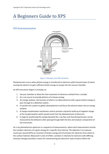
OM Book.book Page 14 Wednesday, April 3, 2013 1:39 PMTechnical OverviewWARNING: Before working inside your computer, read the safety informationthat shipped with your computer and follow the steps in "Before You Begin" onpage 11. After working inside your computer, follow the instructions in "AfterWorking Inside Your Computer" on page 13. For additional safety best practicesinformation, see the Regulatory Compliance Homepage atdell.com/regulatory compliance.Inside View of Your Computer45367829110161115141213141power-button assembly2converter board3optical-drive assembly4power-supply unit5hard-drive assembly6cooling vents7processor heat-sink fan8processor heat-sink9wireless mini-card10memory module(s)11system board12mSATA mini-card13coin-cell battery14trim cover15I/O panel16power-supply fan Technical Overview
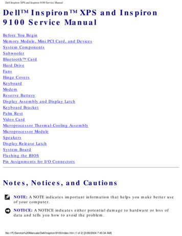
OM Book.book Page 15 Wednesday, April 3, 2013 1:39 PMSystem-Board 87 61wireless mini-card connector2camera-cable connector3memory-module connector(CHANNEL A-DIMM)4memory-module connector(CHANNEL B-DIMM)5mSATA mini-card connector6speaker-cable connector7coin-cell battery socket8power-button cable connector9converter-board cable connector10input source/display-settings controlscable connector11wireless keyboard/mouse receivercable connector12CMOS jumperTechnical Overview 15
OM Book.book Page 16 Wednesday, April 3, 2013 1:39 PM1316I/O-board connector (REAR IO1)14I/O-board connector (REAR IO2)15password jumper16hard-drive data-cable connector17optical-drive data-cable connector18optical-drive power-cable connector19hard-drive power-cable connector20 main (8-pin) power-cable connector21LVDS-cable connector (LVDS1)2223processor socket24touchscreen-cable connector25processor (4-pin) power-cableconnector26processor heat-sink fan-cable connector Technical OverviewLVDS-cable connector (LVDS2)
OM Book.book Page 17 Wednesday, April 3, 2013 1:39 PMRemoving the Back CoverWARNING: Before working inside your computer, read the safety informationthat shipped with your computer and follow the steps in "Before You Begin" onpage 11. After working inside your computer, follow the instructions in "AfterWorking Inside Your Computer" on page 13. For additional safety best practicesinformation, see the Regulatory Compliance Homepage atdell.com/regulatory compliance.Procedure1Place the computer face-down on a clean and flat surface.2Loosen the captive screws that secure the back cover to the inner frame.3Slide the back cover toward the top of the computer and lift the back cover offthe inner frame.321captive screws (2)3inner frame21back coverRemoving the Back Cover 17
OM Book.book Page 18 Wednesday, April 3, 2013 1:39 PMReplacing the Back CoverWARNING: Before working inside your computer, read the safety informationthat shipped with your computer and follow the steps in "Before You Begin" onpage 11. After working inside your computer, follow the instructions in "AfterWorking Inside Your Computer" on page 13. For additional safety best practicesinformation, see the Regulatory Compliance Homepage atdell.com/regulatory compliance.Procedure1Place the back cover over the inner frame and slide the back cover toward thebottom of the computer.2Tighten the captive screws that secure the back cover to the inner frame.3Follow the instructions in "After Working Inside Your Computer" on page 13.18 Replacing the Back Cover
OM Book.book Page 19 Wednesday, April 3, 2013 1:39 PMRemoving the Trim CoverWARNING: Before working inside your computer, read the safety informationthat shipped with your computer and follow the steps in "Before You Begin" onpage 11. After working inside your computer, follow the instructions in "AfterWorking Inside Your Computer" on page 13. For additional safety best practicesinformation, see the Regulatory Compliance Homepage atdell.com/regulatory compliance.PrerequisitesRemove the back cover. See "Removing the Back Cover" on page 17.Procedure1Using a plastic scribe, press-in on the tabs to release the trim cover from theinner frame.2Slide the trim cover toward the top of the computer and then lift the trim coveroff the chassis.1231tabs (2)3trim cover2plastic scribeRemoving the Trim Cover 19
OM Book.book Page 20 Wednesday, April 3, 2013 1:39 PMReplacing the Trim CoverWARNING: Before working inside your computer, read the safety informationthat shipped with your computer and follow the steps in "Before You Begin" onpage 11. After working inside your computer, follow the instructions in "AfterWorking Inside Your Computer" on page 13. For additional safety best practicesinformation, see the Regulatory Compliance Homepage atdell.com/regulatory compliance.Procedure1Insert the tabs at the bottom of the trim cover into the slots on the inner frame.2Press down on the trim cover until the tabs on the inner frame are secured in theslots on either side of the trim cover.Postrequisites1Replace the back cover. See "Replacing the Back Cover" on page 18.2Follow the instructions in "After Working Inside Your Computer" on page 13.20 Replacing the Trim Cover
OM Book.book Page 21 Wednesday, April 3, 2013 1:39 PMRemoving the StandWARNING: Before working inside your computer, read the safety informationthat shipped with your computer and follow the steps in "Before You Begin" onpage 11. After working inside your computer, follow the instructions in "AfterWorking Inside Your Computer" on page 13. For additional safety best practicesinformation, see the Regulatory Compliance Homepage atdell.com/regulatory compliance.PrerequisitesRemove the Back Cover. See "Removing the Back Cover" on page 17.Procedure1Remove the screws that secure the stand to the hard-drive cage.2Lift and slide the stand off the hard-drive cage.121screws (6)2standRemoving the Stand 21
OM Book.book Page 22 Wednesday, April 3, 2013 1:39 PMReplacing the StandWARNING: Before working inside your computer, read the safety informationthat shipped with your computer and follow the steps in "Before You Begin" onpage 11. After working inside your computer, follow the instructions in "AfterWorking Inside Your Computer" on page 13. For additional safety best practicesinformation, see the Regulatory Compliance Homepage atdell.com/regulatory compliance.Procedure1Insert the tab at the top of the stand into the slot on the hard-drive cage.2Align the screw holes on the stand with the screw holes on the hard-drive cage.3Replace the screws that secure the stand to the hard-drive cage.Postrequisites1Replace the back cover. See "Replacing the Back Cover" on page 18.2Follow the instructions in "After Working Inside Your Computer" on page 13.22 Replacing the Stand
OM Book.book Page 23 Wednesday, April 3, 2013 1:39 PMRemoving the Converter BoardWARNING: Before working inside your computer, read the safety informationthat shipped with your computer and follow the steps in "Before You Begin" onpage 11. After working inside your computer, follow the instructions in "AfterWorking Inside Your Computer" on page 13. For additional safety best practicesinformation, see the Regulatory Compliance Homepage atdell.com/regulatory compliance.PrerequisitesRemove the back cover. See "Removing the Back Cover" on page 17.Procedure1Lift the securing tab on the display-backlight cable connector and then disconnectthe display-backlight cable from the convertor board.2Disconnect the converter cable from the converter board.3Remove the screws that secure the converter board to the middle cover.4Lift the converter board off the middle cover.123451screws (2)2converter cable3converter board4securing tab5display-backlight cableRemoving the Converter Board 23
OM Book.book Page 24 Wednesday, April 3, 2013 1:39 PMReplacing the Converter BoardWARNING: Before working inside your computer, read the safety informationthat shipped with your computer and follow the steps in "Before You Begin" onpage 11. After working inside your computer, follow the instructions in "AfterWorking Inside Your Computer" on page 13. For additional safety best practicesinformation, see the Regulatory Compliance Homepage atdell.com/regulatory compliance.Procedure1Align the screw holes on the converter board with the screw holes on themiddle cover.2Replace the screws that secure the converter board to the middle cover.3Connect the converter cable to the converter board.4Connect the display-backlight cable to the convertor board and secure the tab.Postrequisites1Replace the back cover. See "Replacing the Back Cover" on page 18.2Follow the instructions in "After Working Inside Your Computer" on page 13.24 Replacing the Converter Board
OM Book.book Page 25 Wednesday, April 3, 2013 1:39 PMRemoving the Optical DriveWARNING: Before working inside your computer, read the safety informationthat shipped with your computer and follow the steps in "Before You Begin" onpage 11. After working inside your computer, follow the instructions in "AfterWorking Inside Your Computer" on page 13. For additional safety best practicesinformation, see the Regulatory Compliance Homepage atdell.com/regulatory compliance.PrerequisitesRemove the back cover. See "Removing the Back Cover" on page 17.Procedure1Remove the screws that secure the optical-drive assembly to the middle cover.2Gently lift the optical-drive assembly from the middle cover and disconnect thepower and data-cable connector from the optical-drive assembly.34211optical-drive assembly2screws (4)3power and data-cable connector4power and data cableRemoving the Optical Drive 25
OM Book.book Page 26 Wednesday, April 3, 2013 1:39 PM3Remove the screws that secure the optical-drive brackets to the optical drive.4Remove the optical-drive brackets from the optical drive.32261screws (4)3optical drive Removing the Optical Drive21optical-drive brackets (2)
OM Book.book Page 27 Wednesday, April 3, 2013 1:39 PMReplacing the Optical DriveWARNING: Before working inside your computer, read the safety informationthat shipped with your computer and follow the steps in "Before You Begin" onpage 11. After working inside your computer, follow the instructions in "AfterWorking Inside Your Computer" on page 13. For additional safety best practicesinformation, see the Regulatory Compliance Homepage atdell.com/regulatory compliance.Procedure1Align the screw holes on the optical-drive brackets with the screw holes on theoptical drive and replace the screws that secure the optical-drive brackets to theoptical drive.2Connect the power and data-cable connector to the optical-drive assembly.3Align the screw holes on the optical-drive assembly with the screw holes on thechassis.4Replace the screws that secure the optical-drive assembly to the chassis.Postrequisites1Replace the back cover. See "Replacing the Back Cover" on page 18.2Follow the instructions in "After Working Inside Your Computer" on page 13.Replacing the Optical Drive 27
OM Book.book Page 28 Wednesday, April 3, 2013 1:39 PMRemoving the Memory Module(s)WARNING: Before working inside your computer, read the safety informationthat shipped with your computer and follow the steps in "Before You Begin" onpage 11. After working inside your computer, follow the instructions in "AfterWorking Inside Your Computer" on page 13. For additional safety best practicesinformation, see the Regulatory Compliance Homepage atdell.com/regulatory compliance.PrerequisitesRemove the Back Cover. See "Removing the Back Cover" on page 17.Procedure1Remove the screw that secures the memory-module shield to the system-boardshield.2Slide the memory-module shield toward the bottom of the computer and lift it offthe system-board shield.123281memory-module shield3system-board shield Removing the Memory Module(s)2screw
OM Book.book Page 29 Wednesday, April 3, 2013 1:39 PM3Use your fingertips to spread apart the securing clips on each end of the memorymodule connector until the memory module pops up.4Remove the memory module from the memory-module connector.311securing-clips (2)3memory-module connector22memory moduleRemoving the Memory Module(s) 29
OM Book.book Page 30 Wednesday, April 3,
XPS 27 Owner's Manual. Computer model: XPS 2720 Regulatory model: W06C Regulatory type: W06C002. OM_Book.book Page 1 Wednesday, April 3, 2013 1:39 PM