Transcription
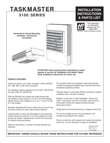
TASKMASTER5100 SERIESINSTALLATIONINSTRUCTIONS& PARTS LISTHorizontal or Vertical MountingIndustrial / CommercialUnit HeaterATTENTION: Read carefully before attempting to install,operate or service the TaskMaster Unit Heater. Retainthese installation instructions for future use.PRODUCT FEATURESForced air electric unit heater available in 208, 240/208,227, 480, 550 or 600 volt as standard.Ten standard heating capacities of 3.3 KW/11,260 BTUHthru 50.0 KW/170, 600 BTUH.208 and 240/208 volt models are single phase fieldconvertible to three phase on 3.3 thru 10.0 KW Models.(Single phase only available on 3.3, 5.0, 7.5 and 10 KW277 volt models.Specially designed inlet louver allows the fan to pull coolair evenly across the high mass all-steel element.Outward drawn venturi and adjustable louver assemblyfurther directs the outlet air in a uniform pattern to meetspecific air pattern requirements in either the horizontalor vertical mounting position.Optional wall/ceiling or vertical mounting brackets (asrequired).Four position weld nuts supplied in case top and backfor field mounting by threaded rods or eye bolt with chain.(Hardware supplied by others).Optional radial or anemostat diffusers lending air patternversatility when mounted vertically.Modular control kits for field installation. Disconnectswitch, thermostat, summer fan switch, heat recoverythermostat. All kits with spade terminals (Exceptdisconnect switch).Single point terminal board wiring of integral control kits.24 volt low voltage control circuit standard on allcontactor and transformer models.Roomy control box with access door locked into positionby two (2) 1/4 turn fasteners for ease of installation.Revised 10/09ECO 1-6174Form 9632IMPORTANT: OWNER SHOULD RETAIN THESE INSTRUCTIONS FOR FUTURE REFERENCE
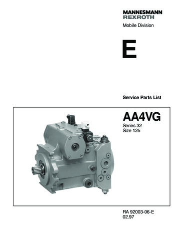
PROPER LOCATION INSTRUCTIONSGENERAL SAFETY INFORMATION / CAUTION:Once the total heating load is calculated, the quantity andcapacity of the unit heaters must be determined. because alarge number of low-capacity heaters provides more uniformheat distribution. This approach is recommended when thearea will be occupied by a relatively large number of sedentary personnel, (i.e. working on production lines and atbenches.)Follow all local electrical and safety codes, as well as theNational Electrical Code (NEC) and the OccupationalSafety and Health Act (OSHA).A large number of smaller capacity unit heaters tends toprevent hot drafts, reduces noise levels, and increasesdiversity of load to help reduce electrical demand andoperating costs.If the power disconnect is not integral and is out-of-sight,lock it in the open position and tag to prevent unexpectedapplication of power prior to performing any service ormaintenance of the unit.In warehouses where even heat distribution and constanttemperatures are less important, a smaller number of highcapacity units can be used -- in many cases reducinginstallation cost. To maintain reasonable heat distributionand reduce severe stratification even in lower bay areas, thetotal air volume of the space should pass through the unitheaters about three times per hour. (Take total cubic feetand divide by 20 in order to determine proper total heaterCFM rating.)The unit when installed must be electrically grounded inaccordance with the National Electrical Code and standard industry practice.It is important that the rated voltage of the heating equipment match the supply voltage. Supply voltage in excess ofthe heater rated voltage can damage equipment. Supplyvoltage lower than the rated heater voltage will decreaseheater output as well as run the risk of damaging somecomponents.Horizontal unit heaters are recommended in low bay areaswith maximum 15 to 18 foot ceilings. These should beconcentrated along outside wall or other areas of greatestheat loss; spaced to set up a generally circular air movement, each heater supporting the air stream of the other.Additional vertical down below unit heaters with appropriateaccessory diffusers can be located to counteract ceilingheat losses (see Figure 1 Location charts).To avoid possible electrical shock, be sure the electricalcurrent is turned off at the main switch prior to wiring orservicing of unit.Make certain that the power source conforms to therequirements of your equipment. See Table 2 on page 6for wire and circuit sizeCheck heater voltage and phase on rating label to confirmthat it matches the electric service supply.Wiring diagrams of the heater and supply connections arepermanently attached to the inside of the heater accessdoor. All terminals are coded in accordance with thewiring diagram. Accessory wiring are shown on the unitwiring diagram and supporting literature.The heater must be mounted at least 7’ above the floor toprevent accidental contact with the fan blade which couldcause injury. Install unit so there are no obstructions to theintake or discharge. Maintain clearances as shown onTable 1, 2, Fig. 1 & 2.The wall/ceiling mounting structure and anchoring provisions must be on sufficient strength to support the combined weight of the heater and mounting bracket.Figure 1 Location InstructionsHHHVVHHHHHHHHEXPOSEDHH2HH
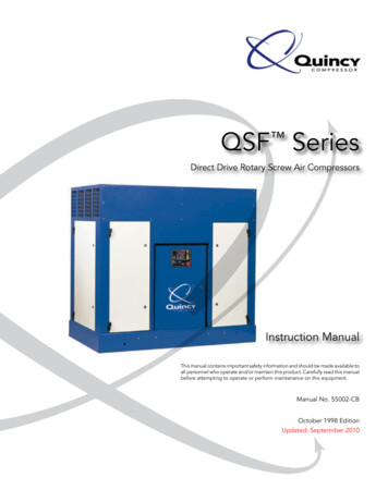
PRINCIPLES OF OPERATIONUpon a call for heat from the floor level or unit mountedoptional accessory thermostat, the unit fan motor andheating elements shall be energized and remain ON untiltemperature reaches setting of thermostat; at which timethe heating elements shall be deenergized.When the unit mounted stratification thermostat closes ona temperature rise and at the same time the floor thermostat calls for heat, the motor shall be energized immediately and the heating element shall be energized, aspreviously described.The fan motor shall continue to run and purge heatercasing of residual heat until setting of fan override isreached, then the fan motor shall be deenergized.The automatic reset safety high limit shall deenergize theheating elements and control circuits should the temperature exceed the setting of this device. The fan safetyoverride shall energize fan motor any time the setting ofthis device is exceeded so as to purge heater casing ofexcess residual heat.For those units with a factory installed two speed fanswitch (25-50KW), the unit as shipped from the factory isset to “low” speed. Customer option to set to “high” speed.For those units available with subdivided circuits, theaccessory two stage thermostat (optional) will, upon a callfor heat, energize fan motor and the first stage heatingelement. Should temperature continue to fall, the thermostat shall energize the second stage heating element.Upon a rise in space conditions towards setting of thethermostat, the two stages of heating elements shall bedeenergized in reverse sequence.The fan motor shall continue to run and purge heatercasing of residual heat until setting of fan override isreached, then the fan motor shall be deenergized.The accessory unit mounted stratification thermostat willenergize the unit heater fan motor upon a rise intemperature above its setting.When the accessory fan switch is placed in the ON position(for summer air circulation), the unit heater fan motor shallbe energized.NOTE: The wall thermostat is to be set to the OFF positionduring this mode of operation (units with contactors).For those accessory thermostats equipped with an integralfan switch, place the switch in the HEAT, or AUTO positionfor operation of the fan and elements which shall then beunder control of the thermostat as described above.When switch is placed in the OFF position, the unit shall bedeenergized. When switch is placed in the FAN position,elements shall be deenergized and fan shall be immediately energized.VERTICAL DISCHARGE UNITS - AIR PATTERNSGeneral Distribution(No Diffuser)Louver Diffuser (Standard)Anemostat Diffuser(Optional)Radial Diffuser (Optional)TABLE 1USEDON3.3 & 5.0 KW7.5 & 10.0 KW15.0 & 20.0 KW25.0 & 30.0 KW40.0 & 50.0 KWSTD X MTG 454N/A Not ApplicableOptional diffusers lend added air pattern versatility toindividual vertical down blow installations as shown inabove illustations.3
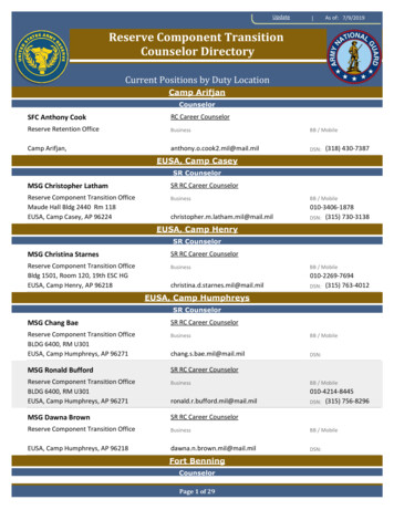
INSTALLATION INSTRUCTIONSTASKMASTER -- 5100 SERIES UNIT HEATERATTENTION: READ INSTRUCTION CAREFULLYAll electric unit heaters are shipped fully assembled.Installation includes hanging the unit, mounting the built-inand remote accessories, wiring of optional control devices,and electrical wiring to the unit.Heaters may be mounted in the horizontal or vertical airdischarge configuration using factory optional suppliedaccessory mounting equipment or using special hardwarefacilities supplied by others.To insure proper delivery of the heated air to desired areas,follow the mounting height and air projection tables includein these instructions. Follow Fig. 1 & 2 for minimum walland ceiling clearances.After the installation is complete, replace the access panel.Set the controls (thermostat, switch) at their desiredcontrol point and apply power to the unit.Check correct operation.DIMENSIONSFIG. 1HORIZONTAL DISCHARGEFIG. 2VERTICAL DISCHARGEDIMENSIONS (INCHES)The wall and/or ceiling structure must be sufficient tosupport the combined weight of the heater and any mounting bracket and accessories.KW3.3 - 5.07.5 - 10.015.0 - 20.025.0 - 50.0Be sure power source is deenergized before installingheater. Check heater voltage and phase listed on heaterdate tape on back of unit to make sure they are the sameas the electrical service -1/229-1/43.3 - 5.0 KWD6-1/26-1/26-1/210-1/167.5 - 20 KWCertain units are convertable from single to three phaseservice. Follow instructions noted on the unit wiring diagram for this conversion. Units that carry a dual voltagerating (HF) require specific wiring changes when convertingfrom 240 to 208 volt service supplied.(4) 5/16" K.O.Open the access panel (2 1/4 turn fasteners).9/16" K.O.9/16" K.O.Remove the desired knock-out(s) on back of the heater.(4) 5/16" K.O.9/16" K.O.1/2" K.O.3/4" - 1" K.O.3/4" K.O.1/2" K.O.1/2" - 3/4" K.O.9/16" K.O.Install any optional accessories following their installationinstructions before mounting unit. Following the correctunit/accessory wiring diagram, connect the power supply,electrical ground and accessories to the correct terminalsor termination points using accepted practices.vertical discharge* Formounting bracketDiagrams not to scaleNET JUNCTION BOX VOLUMEKW43.3 - 57.5 - 1015.0 - 2025.0 - 50CUBIC INCHES74.4198198341CC12193245324555929/16" K.O.
INSTALLATION INSTRUCTIONSTASKMASTER -- 5100 SERIES UNIT HEATER (part 2)HORIZONTAL -- AIR DISCHARGE MOUNTINGSHOWN IN: FIGURE 5 & 6VERTICAL -- AIR DISCHARGE MOUNTINGSHOWN IN: FIGURE 7Swivel hanger brackets may be used to suspend unitheaters from either the wall (figure 5) or the ceiling(figure 6). Attach hanger base “A” to top of heater withthe four 5/16 X 18 caps screws and lockwashers (provided in envelope).Attach short angle brackets “A” to back of heater withfour 5/16 X 18 capscrews “B”, lockwashers “F”. Be surevertical leg of angle brackets face top and bottom ofheater.Attach main hanger frame “B” to wall or ceiling indesired location using lag screws “C” or other suitableattachments (supplied by others).Lift heater into position inserting stud “D” through holein main hanger frame and attach lock nut “provided inenvelope) “E” tightening to within two turns of beingtight.Swivel heater to desired position, tighten lock nut.Figure 5WALL MOUNTHORIZONTAL DISCHARGEAttach inverted U frames “D” to short angle bracketswith four 5/16 X 18 capscrews “K”, washers “L”,lockwashers “M” and nuts “N”.Attach long angle brackets “J” to inverted frames “D”with four 5/16 X 18 capscrews “K”, washers “L”,lockwashers “M” and nuts “N”.Attach heater and bracket assembly to ceiling indesired location using customer supplied equipmentsufficient to support the assembly.Figure 7CEILING MOUNTVERTICAL DISCHARGEFigure 6CEILING MOUNTHORIZONTAL DISCHARGENOTE: When mounting heater using 5/16” all threadrod (by others) do not screw the rod more than 1/2”beyond the inside of the case.5
5100 SERIES UNIT HEATERELECTRICAL DATA (Table 2)CATALOGNUMBERKWRATINGBTU/HR(000)HEATER BRANCH CIRCUITPROTECTIONSIZE(A)SUPPLY WIRESIZE 60o CAWG 6/8104/6823/482*2/361/0*1*/2*42/0*2/0* 5HF1B5105HF2B5105G1G5105P3P5105CA1F2F5107CA1* Use 75 degree C Wire6**Use Copper Conductors on all heaters***This unit (only) built in 7.5 & 110KW case size.
5100 SERIES UNIT HEATERAIR DELIVERY DATACFM /2650FPM 01290/11501870/11601870/1160FAN MOTOR 51/501/501/201/201/121/121/41/4 /1251550/1251550/1311550/131MAX. 91214201822202522AIRTHROWWEIGHTLBS.12 Ft.12 Ft.12 Ft.12 Ft.12 Ft.12 Ft.12 Ft.12 Ft.12 Ft.12 Ft.12 Ft.12 Ft.22 Ft.22 Ft.22 Ft.22 Ft.22 Ft.22 Ft.22 Ft.22 Ft.22 Ft.32 Ft.32 Ft.32 Ft.32 Ft.32 Ft.45 Ft.45 Ft.45 Ft.40 Ft.40 Ft.40 Ft.55 Ft.55 Ft.55 Ft.50 Ft.50 Ft.50 Ft.12 Ft.22 Ft.22 Ft.32 Ft.32 Ft.45 Ft.40 Ft.55 Ft.50 Ft.12 Ft.22 Ft.22 Ft.32 Ft.37 Ft.45 Ft.40 Ft.55 56512012012012050505065651201201201207
5100 SERIES UNIT HEATERTROUBLE SHOOTING GUIDESYMPTOMPOSSIBLE CAUSE(S)CORRECTIVE ACTIONThermostat calls forheat, but heater doesnot function.1. Open (blown) fuse1. Replace fuses, check for cause.(see Replacement Parts List for fuse size)2. INCORRECT WIRING2. CHECK WIRING CONNECTIONS3. Thermal cut-out open,deenergizing heaterelement and controlcircuit.Fan motor runs“HOT”Fan motor runs,but no heat.3. Check for the following:--- Correct supply volts and phase--- Correct control wiring (heater controlmust be thru thermostat control wiringsection only).--- Power interruption to heater duringheater operation.--- Restriction of air around heater 1-5minute fan purge after thermostat off.1. Dust accumulation orexcessive dirt on motor1. Clean fan motor and casing of greaseand oil accumulation.2. Dirt accumulation2. Clean louvers and between heatingelements.3. Motor needs lubrication.3. See Maintenance.1. Element contactor notoperating correctly.1. Check wiring for open circuit. Replacecontactor if defective2. Element fuse blown.2. Replace fuses, check for cause. (seeReplacement Parts List for fuse size)MAINTENANCECAUTION: Make certain that the power source is disconnected before attempting to service or disassemble anycomponet. If the power disconnect is out of the line of sight, lock it in the OPEN position and tag to prevent theapplication of power.ELECTRICALOnce a year inspect the control panel wiring to make certain insulation is intact and all connections are tight. Inspectall heater and relay contacts. If the contacts appear badly pitted or burned, replace the contactor / relay.CLEANINGClean the unit casing, fan and motor once a year. A dirty motor will tend to run hot and eventually will be damagedinternally. Any rust spots on the casing should be cleaned and repainted.LUBRICATIONAll units up to 20KW have fan motors that are permanently lubricated so that only occasional cleaning is required.Units above 20KW have fan motors lubricated for 5 years of continuous duty of 10 years of intermittent operations.When required, remove the oil access plug on back of heater at motor intake grill, open oil cap, fill with S.A.E. No.10 electric motor oil, replace plugs and access plug.8
5100 SERIES UNIT HEATERWIRING DIAGRAM SCHEDULEDIAGRAMNO.MODEL CODEPREFIXMODEL CODESIZE AND CONTROL 3PF3FHF3BF3FF3FHF3BHF3BP3P, T3TP3PP3PU3H, A4N5140CA4N5150CAIN9
5100 SERIES UNIT HEATERPARTS LIST - CATALOG MOTORELEMENTASSY.AUTO.RESETFANOVERRIDEXFMRS.D. FUSE6 RQDS.D. FUSE2 OR3.3 - 57.5 - 1015 - 2025 - 3040 - 150CA1LP3P5150CA1N10LOUVER(5) 56986-001(7) 56986-003(7) 56986-003(9) 56987-001(9) 56987-001Revised 15-001CONTACTOR POWER2 112-00157090-00157112-00157112-00157090-001
5100 SERIES UNIT HEATERPARTS LIST - CATALOG NUMBERS - 600 VOLT MODELSMOTORELEMENT ASSY.AUTO RESET LIMITFAN OVERRIDEXFMRCONTACTORPOWER TRML. BLOCKFAN BLADETERMINAL BLOCKGROUND 6811-00157641-003 86-003 57641-001 86-003 6986-003 57641-002 86-003 (7)MOTORELEMENT ASSY.AUTO. RESET LIMITFAN OVERRIDEXFMRCONTACTORPOWER TRML. BLOCKFAN BLADETERMINAL BOARDGROUND CONN.LOUVERXFMR PRI FUSE BLOCKXFMR PRI FUSE (2)FAN SPEED SWMOTOR 11-00257641-00158027-043 3-00157644-001 57640-00556811-00257641-00158027-043 3-00157644-001 57640-00556811-00257641-004(350VA)58027-043 3-00157644-001 57640-00556811-00357641-00458027-043 3-00157644-001 (2)57112-00157100-001MOTORELEMENT ASSY.FAN OVERRIDEXFMRCONTACTORPOWER TRML. BLOCKFAN BLADETERMINAL BOARDGROUND -003(7)MOTORELEMENT ASSY.AUTO RESET LIMITFAN OVERRIDEXFMRCONTACTORPOWER TRML. BLOCKFAN BLADETERMINAL BOARDGROUND CONN.LOUVERFAN SPEED SWITCHMOTOR 11-00260719-01858027-043 (2)57098-00157114-00156809-001398156986-004 57640-00556811-00260719-01858027-043 (2)57098-00157114-00156809-001398156986-004 57640-00556811-00260719-01858027-043 (2)57098-00157114-00156809-001398156986-004 57640-00556811-00260719-01858027-043 (2)57098-00157114-00156809-001398156986-004 -00156809-001145856986-003 7)11
LIMITED WARRANTYProducts manufactured by TPI Corporation are warranted to the original consumer to be free from defects inmaterial and workmanship for twelve (12) months from the original purchase date.The TPI limited warranty does not cover products that have been modified outside of our factory, damage orfailure caused by acts of God, abuse, misuse, connected to or placed on other than rated voltage, abnormalusage, fault, installation, failure to follow suggested maintenance procedures enclosed with the product,improper maintenance or any repairs other than those provided by an authorized TPI service center.There are no obligations or liabilities on the part of the Corporation for consequential damagesarising out of or in connection with the use or performance of the product or other indirect damageswith respect to loss of property, revenues, profit, costs of removal installation, or reinstallation.All implied warranties with respect to TPI products, including implied warranties for mechantabilityand implied warranties for fitness, are limited in duration to twelve (12) months from original date ofpurchase, except those products or parts of products which are warranted for long periods. On suchproducts or parts of products all implied warranties for merchantability and fitness are limited to theduration of the extended warranty period thereon.Some states do not allow the exclusions or limitation of incidental or consequential damages and somestates do not allow limitations on how long an implied warranty lasts. The above exclusions or limitationsmay not apply to you.During the warranty period, TPI Corporation will, at its sole option, repair or replace any defective parts orproducts returned, freight prepaid, to the TPI Corporation factory or such other locations as TPI Corporationmay designate. Returned products must be packaged carefully and TPI Corporation shall not be responsiblefor damage in transit.When returning parts, the owner must provide the model number of the product and nature of difficulty beingexperienced. This warranty does not obligate TPI Corporation to bear the cost of labor in replacing anyassembly, unit or componet part thereof, nor does the company assume any liability for secondary charges,expenses for installing or removal, freight or damages. There will be charges rendered for product repairsmade after the warranty period has expired. Proof of purchase, including date, must accompany request forin-warranty service. In any event, TPI Corporation’s maximum liability shall not in any case exceed the listprice for the product claimed to be defective. This warranty gives to you specific legal rights and you mayhave other rights, which may vary from state to state. For the name of your nearest authorized TPI Corporation service center, please write to TPI Corporation, P.O. Box 4973, Johnson City, TN 37602.Heating Products Warranty CoverageElements in 198 Series PortableElements in BaseboardsAll Other Heating ProductsThermostats and ControlsLife of heater10 Years1 Year2 YearsVentilation Products Warranty CoverageSeries HD or HDH FansSeries UHP of IHP FansAll other Ventilation Products5 Years3 Years1 Year
TASKMASTER5100 IONS&&PARTSPARTS LISTLISTMontage horizontal ou verticalradiateur industriel et commercialATTENTION: Lisez les instructions soigneusement avant de commencerl’installation, la mise en marche ou l’entretien du radiateur taskmaster.Gardez ces instructions pour utilisation ulterieure.CARACTERISTIQUESRadiateur electrique ventilateur, disponible suivant lestensions standards de 208, 240/208, 277, 480 ou de 600volts.Dix puissances de chauffage standard de 3.3 KW/11,260BTUH jusqu’ a 50.0 KW/170, 600 BTUH.Les modeles unipolaires de 3.3 jusqu a 10.0 Kw de 240/208 volts peuvent se transformer sur le chantier en modeletripolaire. (Les modeles uipolaires de 3.3, 5.0, 7.5 et 1
Forced air electric unit heater available in 208, 240/208, 227, 480, 550 or 600 volt as standard. thru 50.0 KW/170, 600 BTUH. 208 and 240/208 volt models are single phase field convertible to three phase on 3.3 thru 10.0 KW Models. (Single phase only available on 3.3, 5.0, 7.5 and 10 KW