Transcription
Revised January 2007Guide to Insulating Sheathing
Table of ContentsIntroduction . 3Background . 4Material Properties. 6Types of Foam. 6Thermoplastics. 6Thermosets . 6R-value . 7Permeance . 7Durability. 8Technical Concepts . 9Additional Thermal Resistance. 9Rain Water Management. 12Vapor Management . 14Condensation Resistance. 15Design and Construction . 20General Installation. 20Cladding Attachment . 21Roof Connection. 21Foundations Connection. 22Window installation. 24Related Concepts. 28Advanced Framing . 28Cross Bracing and Inset Shear Panels . 29
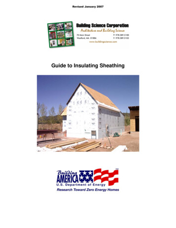
IntroductionResidential housing design continues to move towards the development of high performance sustainablebuilding systems. To be sustainable, a building must not only be efficient and durable but alsoeconomically viable. From this, new methods of enclosure design have been examined that provide highthermal performance and long-term durability but also take opportunities to reduce material use (includingwaste), simplify or integrate systems and details, and potentially reduce overall initial costs ofconstruction.One concept relating to enclosure design is to incorporate the use exterior foam insulating sheathing intothe construction of the wall assembly. As with any building enclosure system, appropriate detailing forthe management of water, vapor, and energy transfer are necessary.Guide to Insulating SheathingBuilding Science CorporationPage 3 of 30
BackgroundAs the desire to provide more thermally efficient enclosure assemblies increased so did the problems withmoisture accumulation within building enclosure assemblies. Often the problems occurred due to newmaterials being introduced into the designs for specific purposes, without adequate understanding of all oftheir properties and the potential impacts on the assembly as a whole. Many enclosure failures occurreddue to the lack of appreciation that products and materials have other properties than the ones that theyare initially designed for.moc.eThough these lessons were hard learned, we can now use this knowledge for our benefit. Throughexamining and understanding materials based on all of their properties (not just what they were initiallycreated for), we can eliminate redundancies in enclosure design, making the systems simpler and morecost effective.cneicsIn cold climates the use of exterior rigid insulation sheathing boards has been a method of increasingthermal performance of the enclosure, as well as a means of reducing the condensation potential withinexterior wall assemblies. This concept, while not new, has become more accepted in recent years and isbeing used in residential construction. While this method has proven to be effective, it was introduced asan addition to standard residential construction for a specific purpose. The base wall assembly generallyremained unchanged, with other materials used for air sealing and water management.gnildiumoc.ecneThe opportunity that presented itself was the integration of the exterior rigid insulation board into theenclosure assembly to act not only as insulation but also as the primary sheathing and, in certain areas,as the drainage plane and vapor control layer for the wall assembly. This system combined withadvanced framing concepts can provide cost savings from the reduction of building materials used (fewerstuds, the elimination of plywood or OSB sheathing, and housewraps), and the reduction of constructionwaste (incorporating standard construction product dimensions in the design of the building to minimizecutting). b icsgnildiu.ecb mocbGuide to Insulating SheathingsgnidliuneciBuilding Science CorporationPage 4 of 30
icsb While the use of exterior insulation was initiallyused in cold climates, the benefits of theintegrated system from increased thermalperformance and reduced costs make it viable inother climates zones as well.cnegnildiumoc.ec.ecneicsgnildiumoStill, proper understanding of the type ofenclosure assemblies suitable for the overallclimate zone in which the house is beingconstructed is critical. The choice of materialsused will vary from climate zone to climate zoneand the details for the water resistant barrierbecome more critical in areas of increasedrainfall.moc.ecbThis guide examines the application of insulatingsheathing to exterior wall assemblies, from thetechnical conceptual design and benefits to theinstallation and interaction with other buildingsystems. bGuide to Insulating SheathingsgnidliuneciBuilding Science CorporationPage 5 of 30
Material PropertiesThere are three main types of insulating sheathing currently being used in the industry: ExpandedPolystyrene (EPS), Extruded Polystyrene (XPS), and Polyisocyanurate (Polyiso). Each of these productsall has a different set of physical properties that will affect the dynamic of the wall assemblies in regardsto the transmission and management of heat and moisture.Types of FoamInsulating foam sheathings are split into two basic categories: 1) thermoplastics, 2) thermosets. BothEPS and XPS foams are thermoplastic foams, while Polyisocyanurate is a thermoset foam.ThermoplasticsThermoplastics are based on linear or slightly branched (non-cross linked) polymers. These foams havea definite melting range and will soften and melt at elevated temperatures. They are also more prone toreact and degrade when in contact with some organic solvents as found in some paints, adhesives, andfuels. Therefore it is important to only use manufacturer approved compatible materials when usingthermoplastic foams.Of the thermoplastic foams, EPS and XPS are the most common used in the industry. Both products are1based on polystyrene resin and are considered to be closed cell rigid foams.The manufacturing of EPS involves the expanding of polystyrene beads to fill a mold. The densities ofEPS foam can be varied if desired. Increased density results in increased thermal resistance andcompressive strength. The density of the product also affects the vapor transmission. While EPS is aclosed cell foam (slow water vapor and air transmission through the cell walls), the gaps between thecells will still allow for moisture to pass through the matrix. With increased density, these spaces arereduced and the ability of the foam to allow water transmission is reduced.XPS foams are formed by mixing molten polystyrene with a blowing agent at the correct time, at anelevated temperature, and at an elevated pressure and then extruding the foam through a die to theatmosphere. This creates a more regular cell structure providing for better strength properties and higherwater resistance that EPS foams. The density of XPS foams can also be varied, allowing for increasedcompressive strength, however due to the more regular cell structure, this has little to no effect on thevapor transmission properties.ThermosetsThermoset plastics are based on cross linked polymers. This will allow thermoset plastics to be used forhigher temperature applications as they do not usually exhibit a melting range and will instead char andburn. Thermoset foams are also generally more resistant to solvents and chemicals.The most common thermoset foam on the market is polyisocyanurate. While traditional polyurethanefoams were created by reacting isocyanate with polyol (and other blowing agents, catalysts, andsurfactants) polyisocyanurate foams can theoretically be created with no polyol, using only isocyanatereacting with itself (and other blowing agents, catalysts, and surfactants). In general though, commercialpolyisocyanurate foam used in the market is really polyurethane foam modified with polyisocyanurate or a“blend” of the two foams. The use of the blend increases the fire resistance while maintaining the thermalresistance and strength of the material.1Closed cell foams, as apposed to open cell foams, have a higher resistance to air and vapor flow due tothe cell walls being continuous.Guide to Insulating SheathingBuilding Science CorporationPage 6 of 30
R-valueThe thermal resistance of each of the products will vary. In general, EPS foam has the lowest R-valueper inch, with XPS being slightly more efficient, and with Polyisocyanurate having the best R-value perinch. The R-value of EPS foams can be increased by increasing the density of the product, however, themore dense expanded foams are less common in the market. Typically EPS foam has a rated value ofapproximately R-4 per inch. XPS foams are pretty consistent with an R-value of approximately R-5 perinch.While the thermal resistance of these thermoplastic foams is generally stable over the long term andtherefore the initial R-value at the time of manufacturing will not change over time, polyisocyanuratefoams are rated with a Long Term Thermal Resistance (LTTR) R-value representing a 15 year weightedR-value. This is in response to issues of thermal drift of the polyisocyanurate products. Thermal driftoccurs due to the gasses produced during the forming of the foam. These gasses slowly diffuse out ofthe product over time and are replaced by air. Since these gasses also have more thermal resistancethan air, the R-value of polyisocyanurate diminishes over time as the gasses diffuse out of the product.Facings on the insulation board, such as aluminum foil, will slow this process down as the diffusion canonly occur out the edges of the product and not through the front and back faces. Most polyisocyanurateproducts have an LTTR R-value of R-6.5 per inch.PermeanceThe permeance of the materials is important when examining the vapor control strategy of the wallassembly. Materials can be separated into four general classes based on their permeance:Vapor impermeable0.1 perms or less(Class I vapor retarder – considered a vapor barrier)Vapor semi-impermeable1.0 perms or less and greater than 0.1 perm(Class II vapor retarder)Vapor semi-permeable 10 perms or less and greater than 1.0 perm(Class III vapor retarder)Vapor permeablegreater than 10 perms(Not considered a vapor retarder)For unfaced insulation, the permeability is a function of the material thickness. In general most productmanufacturers list the permeance of the material based on a thickness of 1 inch. Increasing ordecreasing the thickness of the material will affect the permeance. This can become an issue when usingXPS foam insulation. 1 inch of XPS has a permeance of 1.1 perms (borderline Class II and Class IIIvapor retarder), increasing the thickness to 2 inches decreases the permeance to 0.55 perms (middle ofthe Class II vapor retarder). Therefore, 1 inch of XPS is considered to be vapor semi-permeable, while 2inches is considered to be vapor semi-impermeable.For faced rigid insulation boards (such as foil faced or glass fiber faced polyisocyanurate), the permeanceof the facing is often much lower than the permeance of the polyisocyanurate and will govern the overallpermeability of the sheathing board. For these products, the permeance will not change with increasingthickness.Guide to Insulating SheathingBuilding Science CorporationPage 7 of 30
Table 1: Material PropertiesExpanded Polystyrene (EPS)R-value/inch @ 502.00Permeance(perms)5.005.003.502.00Water Absorption(% by volume)4.04.03.02.0Compressive 2.002.77 - 4.490.03 1.01.01.02525Extruded Polystyrene (XPS)Polyisocyanurateunfaced*foil facedglass fiber facedDurabilityInsulating sheathings are generally fairly durable materials, however, they are not completely resistant todegradation. Polystyrene boards will degrade if left exposed to UV radiation for prolonged periods oftime. The boards will discolor and a thin dusty film will form on the boards. Faced Polyisocyanurate ismore resistant to UV degradation, however the unfaced polyisocyanurate boards are also susceptible toUV degradation.EPS boards are less durable for excessive handling. The edges of the boards can break off as the bondbetween the expanded beads is not as strong as the matrix formed with XPS and polyisocyanurate. Thiscan leave the boards with more rounded edges and decrease the thermal value at the joints between theboards. Careful cutting and handling is recommended when using EPS boards.Most insulating sheathing boards are resistant to moisture, however problems with warping and cuppingof the foil faced polyisocyanurate have occurred in the past when the boards have been left exposed tothe weather for extended periods of time.As a general rule, it is considered good practice to store the boards in a protected, covered, and drylocation on site and to limit the amount of time the boards are left exposed before being covered over bythe cladding material.Guide to Insulating SheathingBuilding Science CorporationPage 8 of 30
Technical ConceptsAdditional Thermal ResistanceWith rising utility cost, designing homes to be more energy efficient is increasing in importance. Part ofthe overall efficiency of a house is the thermal resistance of the various enclosure assemblies. Commonresidential construction use wall framing based on either 2x4 or 2x6 dimensional lumber with insulationinstalled in the stud cavities created by the framing members. With cavity insulation the overall thermalresistance can be varied somewhat, by using different types of insulation, varying the installationmethods, and varying the stud spacing, but there is still a limit because of the depth of the stud cavity.Adding insulating sheathing to the exterior of the assembly is a simple method of increasing the overallthermal resistance of the wall assembly beyond that possible with cavity insulations and therebyincreasing the overall efficiency of the house.When examining the overall thermal resistance of the wall assembly, the effective R-value must beconsidered. A simple method than can be used to estimate the effective R-value of the cavity space isthrough using the isothermal planes method set out in Chapter 25 of the ASHRAE Fundamentals 2005.While this method is not as accurate as some other more sophisticated computer simulation models, it isa means to get a rough idea of the effective insulating value of an assembly. With the isothermal method,the effective R-value of the cavity assembly is a proportional sum of the various U-values of the differentcomponents based on material fractions.U(cavity) U(studs)·F(studs) )U(insulation)F(studs)F(insulation) average U value of the insulation and studs U value of wood framing U value of cavity insulation fraction of area of studs, headers, and sill plates fraction of area of insulationTherefore the effective R-value of the cavity can be expressed as:R(cavity) 1/U(cavity)The overall R-value of the assembly is a sum of the thermal resistance of all of the components.R(total) R(comp 1) R(comp 2) R(comp n)Where:R(total)R(comp) total R-value of the assembly individual effective R-value of each material layerAs an example the effective cavity insulation value and the total effective R-value for various assemblieswere calculated. The fiberglass batt or blown cellulose may be rated as R-19, however due to the woodstuds and other framing members the effective thermal resistance may be as much as 35% less than therated cavity insulation, leaving an effective value of only R-12.5 for the cavity as seen in the calculationsbelow.Guide to Insulating SheathingBuilding Science CorporationPage 9 of 30
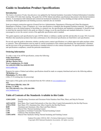
tside Air Film1/2" Plywood2x6 Wood Stud5.5" Fiberglass Batt1/2" InteriorGypsumInterior Air FilmTotalThe effective R-value of the following assembly with a 23%framing fraction is:R(cavity) 1/[(0.77/19) (0.23/5.83)]R(cavity) 12.5R(total) 0.17 0.62 12.5 0.45 0.68R(total) 14.42Insulating sheathing provides additional insulation to the house that is run continuous past the exteriorface of the wood studs. Because of this the rated R-value for the insulating sheathing is very close to theeffective R-value of the insulating sheathing in the assembly. With the lack of framing penetratingthrough the layer insulating sheathing, the whole R-value can be generally be used. This allows for largeincreases in the effective R-value of the assembly without substantially increasing the thickness of 0.6812.75Outside Air Film1" Rigid Insulation1/2" Plywood2x6 Wood Stud5.5" Fiberglass Batt1/2" InteriorGypsumInterior Air FilmTotalIncorporating 1 inch of rigid insulation into the design of theprevious example wall assembly yields the followingeffective R-value for the assembly:R(cavity) 1/[(0.77/19) (0.23/5.83)]R(cavity) 12.5R(total) 0.17 5 0.62 12.5 0.45 0.68R(total) 19.42Adding one inch of insulating sheathing (R-5 for this example) will increase a 2x6 stud wall from aneffective R-14.4 to an effective R-19.4. This represents an increase of 35% effective thermal resistancewith only 15% increase in the overall wall thickness.Guide to Insulating SheathingBuilding Science CorporationPage 10 of 30
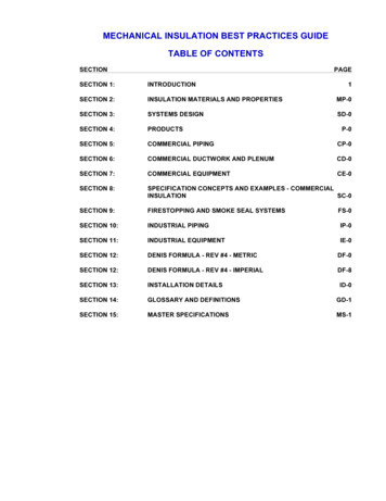
ElementOutside Air Film1" Rigid Insulation2x6 Wood Stud5.5" Fiberglass Batt1/2" InteriorGypsumInterior Air 5.30.450.6812.13If the insulating sheathing is used as the primary sheathing(eliminating the plywood or OSB from the exterior)R(cavity) 1/[(0.77/19) (0.23/5.83)]R(cavity) 12.5R(total) 0.17 5 12.5 0.45 0.68R(total) 18.80With this configuration the wall thickness is only increased by 8% while the effective thermal resistanceincreases from R-14.4 to R-18.8, a 31% .13Outside Air Film2" Rigid Insulation2x6 Wood Stud5.5" Fiberglass Batt1/2" InteriorGypsumInterior Air FilmTotalIncorporating 2 inches of rigid insulation into the design ofthe example wall assembly yields the following effective Rvalue for the assembly:R(cavity) 1/[(0.77/19) (0.23/5.83)]R(cavity) 12.5R(total) 0.17 10 12.5 0.45 0.68R(total) 23.80Adding two inches of rigid insulation to the exterior (R-10) will increase the effective R-value from R-14.4to R-23.8. This represents an increase of 65% over the original effective R-value. buildingscience.comGuide to Insulating SheathingBuilding Science CorporationPage 11 of 30
Rain Water ManagementFor most climate zones the management of exterior rain water is the most critical aspect of the moisturemanagement system of the building enclosure. The fundamental principle of water management is todrain the water downwards and outwards out of the building and away from the building. In order for thebuilding and building assemblies to drain properly, detailing of the drainage plane must be carefullydesigned.There are several options for creating a drainage plane in the wall assembly. The choice of whichmethod to use is based on weighing the risks involved.Water ResistanceAs the water penetration resistance of the assembly increases, the risk of moisture problemsdecreases.Moisture Tolerance of AssemblyAs the moisture tolerance of the materials that comprise the assembly increases (masonry andconcrete vs. wood and steel) the risk of moisture related problems decreases.ExposureAs the exposure to rainfall increases, the risk of moisture related problems increases.RainfallAs the amount of rainfall increases, the risk of moisture related problems increases.Drying PotentialAs the ability of an assembly to dry increases due to the climate, design, or both, the risk ofmoisture related problems decreases.WorkmanshipAs the craftsmanship of the construction of the assemblies and their connection details increases,the risk of moisture related problems decreases.Guide to Insulating SheathingBuilding Science CorporationPage 12 of 30
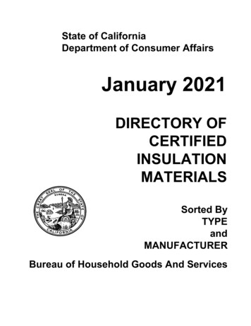
There are four strategies proposed for maintaining the continuity of the drainage plane with theincorporation of insulating sheathing to the exterior.moc.ecneicsgni buildWall Section 1 - Insulating Sheathing and Housewrap overPlywood or OSB: The first strategy involves installing theinsulating sheathing over top of a layer of building paper orhousewrap and wood sheathing. This is the most durableassembly proposed in this guide as the drainage plane material(building paper or house wrap) is supported by the plywoodsheathing, and protected against wind loading and otherenvironmental factors by the insulating sheathing. This type ofassembly would be recommended in areas or high exposure andrainfall.moc.ecneicsgni buildWall Section 2 - Insulation Sheathing and Housewrap overWood Studs: The next proposed strategy is to install theinsulating sheathing overtop of a housewrap that is stretchedover wood studs. In this configuration, the housewrap drainageplane is protected from exterior elements (excessive windloading, and rain exposure). The type of assembly would workeffectively in most rainfall zones, though potentially not in highexposure locations. With the lack of wood sheathing support onthe exterior of the framing more care is required during theinstallation of the housewrap and insulating sheathing.Wall Section 3 - Housewrap installed over InsulatingSheathing and Wood Studs: The third strategy would be toinstall the housewrap to the exterior of the insulating sheathing,essentially replacing the plywood or OSB in a traditional wallassembly with insulating sheathing. The housewrap is moreexposed to exterior elements such as wind loading and moistureand may not be as durable as the other approaches. In additionthe fasteners used to install the housewrap must be able topenetrate all the way through the insulating sheathing and intothe wood studs beyond. This wall approach would functionadequately in most rainfall zones.moc.ecneicsgni buildWall Section 4 - Insulating Sheathing as the Drainage Plane:The final approach would be to use the insulating sheathing asthe primary sheathing and drainage plane of the assembly. Inorder to achieve this all the vertical joints must be taped orsealed and special flashing details must be used. With somequestion as to the long term dimensional stability of insulatingsheathing products, this approach is considered to be in thehigher risk category and should only be used in areas withlimited rainfall and exposure, where rain water management isnot as critical.moc.ecneicsgnidl buiGuide to Insulating SheathingBuilding Science CorporationPage 13 of 30
Vapor ManagementThe design of the vapor management system should attempt to allow maximum drying of the wallassembly from diffusion, while limiting the amount of moisture able to be driven into the assembly. Wherepossible, drying to both sides of the construction assembly is encourage, however in some circumstancesmore stringent vapor control is required. As a general rule for standard framed construction, the vaporretarding layer should be placed to the interior of the assembly in cold climates (reducing the water vaporfrom the higher humidity interior air from diffusing into the assembly), while in hot humid climates, thevapor retarding layer should be placed to the exterior of the assembly (reducing the water vapor from thehot humid outside air from diffusing into the assembly).moc.ecneicsgni buildTherefore, in a general sense, for cold climates it is preferable to use a more vapor permeable insulatingsheathing (such as EPS and unfaced XPS) on the exterior and in hot humid climates, it is preferable touse a more vapor impermeable sheathing on the exterior of the assembly (such as foil facedpolyisocyanurate and plastic film faced XPS).For mixed humid climates, the system choices become more difficult as the assembly needs to beprotected from wetting from both the interior as well as the exterior. The drying can be predominantly tothe exterior, the interior, or in both directions in a flow through type assembly. Often these strategiesneed to be combined with other vapor management strategies such as building pressurization (ordepressurization) and supplemental dehumidification. There is also a strategy to place the vapor controllayer towards the middle of the assembly. This approach will be discussed in the next section onCondensation Resistance.moc.ecneicsgni buildmoc.ecneicsgni buildmoc.ecneicsgnidl buiThere are also some exceptions. With absorptive claddings such as brick veneer and stucco, a highinward vapor drive can occur due to solar radiation heating up the wet cladding and creating a high vaporpressure difference between the brick (or stucco) and the exterior and the brick (or stucco) and theinterior. This vapor pressure differential will cause moisture to be driven into the assembly if there is notadequate vapor control on the exterior. For this reason, insulating sheathing that is installed behind amasonry veneer or stucco should be vapor semi-impermeable or it can be semi-permeable if combinedwith an impermeable or semi-impermeable membrane.Guide to Insulating SheathingBuilding Science CorporationPage 14 of 30
moc.ecneicsgni buildmoc.ecneicsgni buildCondensation ResistanceCondensation can occur when moisture laden air comes in contact with a material with a surfacetemperature below the dewpoint temperature of the air. In a cold climate wall assembly, this usuallyoccurs at the interior face (or back side) of the exterior sheathing when moisture from the conditionedspace penetrates into the wall assembly through vapor diffusion or air movement. The addition ofinsulating sheathing to the exterior of an assembly in colder climates can provide for some condensationresistance within the wall assembly as it will change the thermal gradient through the assembly.The thermal gradient across an assembly describes how the temperature varies from one side of anassembly through to the other. The thermal gradient can be predicted by examining the individualproportion of thermal resistance provided by each component. Each different component will provide apercentage of the total thermal resistance of the assembly. Therefore, the change in temperature of anycomponent is based on the percentage of thermal resistance provided by that component multiplied bythe overall temperature difference across the assembly.moc.ecneicsgni build T(comp) R(comp) / R(total) x (T(in) – T(out))Where: T(comp)R(comp)R(total)T(in)T(out) temperature change across a component thermal resistance of the component total thermal resistance of the assembly interior temperature exterior temperatureTo determine the temperature at any given surface in the assembly, the individual temperature changesacross each component in the assembly up to the desired surface is added to the exterior temperature.moc.ecneicsgnidl buiT(surface) T(out) T(comp 1) T(comp 2) T(comp n)The example below examines the te
XPS foam insulation. 1 inch of XPS has a permeance of 1.1 perms (borderline Class II and Class III vapor retarder), increasing the thickness to 2 inches decreases the permeance to 0.55 perms (middle of the Class II vapor retarder). Therefore, 1 inch of XPS is considered to be vapor semi-permeable, while 2