Transcription
Project No. LDA-1506DESIGN OF A TIEBACK ANCHOR SYSTEMA Major Qualifying Project ReportSubmitted to the Facultyof theWorcester Polytechnic InstituteIn partial fulfillment of the requirements for theDegree of Bachelor of Science in Civil EngineeringSubmitted By:Kelsie LazaroDate Submitted:July 24, 2015Approved By:Professor Leonard D. AlbanoThis report represents the work of a WPI undergraduate student. Submitted to the faculty asevidence of completion of a degree requirement. WPI routinely publishes these reports on itswebsite without editorial or peer review.
AbstractDesign analysis of multiple options for a through-bolt tieback anchor was proposed. The mainobjective of the project was to design an anchor with high constructability while also costeffective for production and sale by MIW Corporation. This objective was met throughengineering drawings and structural analyses of multiple designs, and a multi-attribute analysisidentified the most effective option. The project also included a detailed final design that metstandards imposed by the Occupational Safety and Health Administration.2
Capstone DesignThe project focuses on developing a roof tieback anchor for MIW Corporation to produceand sell. Very few fabricators in the United States produce these items, and they are morecommonly purchased and shipped from countries such as Canada. Recently MIW considered thepossibility of selling their own within the Greater Boston area, which would be at lower cost thanthe Canadian systems due to the proximity of the company to its market.Through-bolt tieback anchors are a safe and practical anchorage solution that is used forfall protection. They have an overall simple design which results in increased productivity for themanufacturer. Prior to producing these systems, the president of the company, George Malatos,wants to ensure he has a cost-effective design that complies with all related specifications. Theproject focuses on fulfilling these needs.This project consisted of four phases: investigation of a benchmark design, creation ofpreliminary designs, analysis and evaluation of alternatives and selection of the best alternative,and preparation of a detailed design. The investigation of the benchmark involved backcalculating the capacity of an existing design, creating a template that simplified the design ofalternatives later in the project. Research was found through investigation of related engineeringstandards.The first step in the creating the preliminary designs was to take into account the requestsand design ideas of the client, MIW Corporation. Research was also completed to identifypossible alternatives that could improve the design’s sustainability and efficiency. Once all theinformation was compiled, five preliminary designs were generated. Different approaches werefollowed to determine the best design for the needs of the company, as well as the requirementsfor fall protection systems.After the preliminary designs were defined, each alternative was analyzed and evaluatedto identify the most efficient design. The designs were analyzed for constructability,sustainability, use flexibility, and cost efficiency. The best design was selected based on thesefour attributes.The completion of this capstone design experience included the following realisticconstraints: economic, health and safety, manufacturability, sustainability, and ethical. The cost3
efficiency was analyzed using material take offs for each of the designs as well as consideringproduction time. Cost factors include the building materials, complexity of fabrication (i.e. manhours for welding), and complexity of erecting.Health and Safety is one the many engineering standards that were upheld throughout theduration of the project. Many of these standards are reflected by OSHA requirements. The maingoal of the project was to design the anchor within Occupational Safety and Health Association’sminimum design requirements for fall back systems in order to ensure safety of workers. Eachdesign alternative was checked to confirm that it complies with all safety regulations.The manufacturability of each design was considered for ease of construction, given theclient’s resources. The client’s shop manager was consulted to review each of the designs to ratethe difficulty of each of the connections as well as the bend in the ¾” bent bar of each design.Sustainability in construction has increased its importance recently. The sustainability ofthe different materials used in the anchor designs were analyzed. Some factors analyzed includedthe protection against corrosion, resistance to fire and overall durability. Better sustainability alsoleads to lower maintenance costs.The ASCE (American Society of Civil Engineers) Code of Ethics was also considered.The Code of Ethics was first adopted in 1914, and is the model for professional conduct forASCE members. The four main principles of the Code of the Ethics assist engineers to upholdand advance the integrity, honor, and dignity of their engineering. While designing the roofanchor, the health, safety, and welfare of the possible users of the product were held in highregard.4
Professional Licensure StatementProfessional Engineering (PE) licensure enforces standards that restrict practice toqualified individuals who have met specific qualifications through their education, workexperience, and passing exams. This ensures a high quality of engineering work. Having a PElicense shows the competence of an individual engineer. These standards are regulated by state inthe United States.Completing the requirements to become a licensed engineer is an extensive process.Obtaining a license is a high distinction that sets some engineers above the rest. It is not arequirement to become a licensed engineer; a non-certified engineer can work under supervisionof one with a license. However, licensed engineers have access to more favorable employmentopportunities, including business ownership. The licensing requirements begin with a completionof a bachelor’s degree at an ABET-accredited engineering program. The next step is passing theFundamentals of Engineering (FE) Exam to become an Engineer-in-Training (EIT). After aminimum of four years of acceptable work experience as an EIT under the supervision of a PE,the more specific Professional Engineering Exam can be taken. Passing the PE Exam along withthe submission of an experience portfolio are the final steps to obtain the PE License.Receiving PE licensure is a symbol of high qualification in the engineering industry. Theachievement of becoming a PE means competence and safety to clients and the public, ability totake on greater responsibilities to an employer, and respect among co-workers and colleagues.Along with the ability to stamp and seal drawings, move up in their career, and performconsulting service, there are many responsibilities that licensed engineers have to follow, such asawareness of legal requirements, ethical conduct, continued education, and participation inprofessional organizations. Licensed engineers combine their skills to create high quality projectswhile upholding the health and safety of the public as one of their main responsibilities.This project involves the analysis of roof anchor design alternatives. Once the design ischosen and completed, it will need to be approved by a professional engineer (PE). AchievingPE approval ensures the design is in compliance with all regulations. This maintains safety andfulfills the Massachusetts General Law that engineering work may be performed only by aProfessional Engineer or under the direct supervision of a PE.5
AcknowledgementsI would like to acknowledge a number of people. Without their contributions, I would not havebeen able to accomplish the goals of this project. These people include: First of all, my advisor, Professor Leonard Albano for his advice, patience and constantsupport throughout the project. George Malatos, owner of MIW Corporation, for allowing me the opportunity tocomplete my MQP with his company and gain valuable professional experience. Mike Walker, shop supervisor at MIW Corporation, for educating me about thefabrication process in steel construction. Jake Hughes, civil engineering teaching assistant at WPI, for his patience and assistancewith the design checks.6
Table of ContentsDESIGN OF A TIEBACK ANCHOR SYSTEM . 1Abstract . 2Capstone Design . 3Professional Licensure Statement . 5Acknowledgements . 6List of Figures . 9List of Tables . 10Chapter One: Introduction . 11Chapter Two: Background . 13Fall Back Protection Systems . 13Governing Standards . 14Structural Design . 14Chapter Three: Methodology . 21Preparation of Benchmark Calculations . 21Creation of Design Alternatives . 22Analysis of Design Alternatives . 24Development of Detailed Design . 25Chapter Four: Preparation of Benchmark Calculations . 27Chapter Five: Creation of Alternative Designs . 35Chapter Six: Analysis of Alternatives . 44Evaluation Criteria . 44Weighted Evaluation . 45Evaluation of Alternatives . 46Chapter Seven: Conclusions and Recommendations . 487
Summary. 48Conclusion . 52References . 53Appendices . 55Appendices A: Project Proposal . 55Appendix B: AutoCAD Drawing of Benchmark Design . 66Appendix C: Hand Calculations of Benchmark Design . 67Appendix D: RISA 3D Results of Forces in Bent Bar in Benchmark Design . 71Appendix E: Preliminary Sketches . 72Appendix F: Hand Calculations of Design #2 . 73Appendix G: Hand Calculations of Design #3 . 77Appendix H: Hand Calculations of Design #4 . 83Appendix I: Hand Calculations of Design #5 . 86Appendix J: Stress Values in Bent Bar for Design #2 . 91Appendix K: Stress Values in Bent Bar for Design #3 . 91Appendix L: Stress Values in Bent Bar for Design #4 . 92Appendix M: Stress Values in Bent Bar for Design #5 . 92Appendix N: AutoCAD Drawing of Design #2 . 93Appendix O: AutoCAD Drawing of Design #3 . 93Appendix P: AutoCAD Drawing of Design #4 . 94Appendix Q: AutoCAD Drawing of Design #5 . 94Appendix R: Atlantic Stainless Steel Estimate. 95Appendix S: AutoCAD Drawings of Recommended Design . 96Appendix T: Hand Calculations of Recommended Design. 97Appendix U: Stress Values in Bent Bar for Recommended Design . 1038
List of FiguresFigure 1: Roof tie-back anchor . 13Figure 2: Tie-down Anchor designed by Olsen Engineers . 15Figure 3: Three radii used in the bending stress calculation of a curved beam . 17Figure 4: RISA3D drawing of top bent bar . 18Figure 5: Benchmark Design Roof Tie-Down Anchor . 27Figure 6: Force Diagrams of Virtual Work of a Half structure with Anti-Symmetric BoundaryCondition. 30Figure 7: Final Results of Shear and Reaction Forces . 30Figure 8: Joint reaction results from computer analysis . 31Figure 9: Bent Bar Connection with a Cap Plate . 35Figure 10: Bent Bar Connection without a Cap Plate . 35Figure 11: Drawing of the typical baseplate design and bolt placement . 37Figure 12: Recommended Design of Roof Tie-Down Anchor . 48Figure 13: Recommended Design of Roof Tie-Down Anchor . 499
List of TablesTable 1: Ultimate and Yield Strength of Carbon vs. Stainless Steel , values based on AISC Table2-4 . 16Table 2: Table of Resistance Factors Used in LRFD Calculations . 20Table 3: Brief explanation of the four phases of the project. 21Table 4: Brief design summary of alternatives . 24Table 5: Stresses Acting on Round Bent Bar in Benchmark Design, based on applied 5000 lbforce . 29Table 6: Table of stress values and the corresponding limits calculated for the benchmark design. 33Table 7: Design drawings and summaries of the five preliminary designs . 39Table 8: The design summary and stress values of the five preliminary designs . 41Table 9: Cost of materials used in anchor designs . 45Table 10: Scores of the three attributes from comparison and resulting weight factors. 46Table 11: The results of the five designs efficiency in sustainability, constructability, useflexibility and cost. 47Table 12: The final scores of the five preliminary designs . 47Table 13: Table of stress values and the corresponding limits calculated for the final design. 50Table 14: Final scores including the recommended design . 5110
Chapter One: IntroductionMIW Corporation has been fabricating and installing miscellaneous and ornamentalmetal since 1972. Originally concentrating on ornamental fences, gates, and rails, the companybegan to flourish with a number of projects in the Back Bay and Greater Boston Area in the1970’s.In 1980, MIW began fabricating and installing more complex miscellaneous andornamental steel after purchasing a small fabricating shop in Roslindale, MA. The company alsostarted producing small to mid-size structural steel projects in 1990. This allowed MIW toexpand their connections within the Boston Market and work on more complex projects.In 2005, MIW became a member of the National Ornamental & Miscellaneous MetalsAssociation (NOMMA) and the American Welding Society (AWS). These two membershipshave allowed MIW to strengthen their networks, and gain numerous resources within theirindustry.After purchasing a larger fabrication shop in Fall River, MA in 2007, the company hasincreased the number and types of equipment for the production of both miscellaneous andstructural steel. Due to this expansion, the company also fabricates both stainless steel andaluminum products.MIW became certified in steel fabrication by the American Institute of Steel Construction(AISC) in 2014. Participating in AISC’s certification program shows the respect and safety MIWholds for its products and employees. Companies achieve a higher quality and value whencertified by AISC.MIW Corporation continues to look for ways to extend its market. One product theywould like to begin producing is tieback anchors. Through-bolt tieback anchors are a permanentanchorage solution that is both safe and practical. They are used for fall protection and a widerange of suspended access uses. Some of these applications include window cleaning andexterior building maintenance.11
The purpose of this project is to design an effective roof tieback system that meets therequirements of the Occupational Safety and Health Administration (OSHA) and The AmericanNational Standards Institute (ANSI) while still cost effective.This report consists of seven chapters. Following this introduction, Chapter Two includesa background about fall back protection systems, the governing factors and design approachestaken in the design process. The third chapter provides a brief overview about the methodologyof the project. Chapter Four explains the calculations and design process of the first, benchmarkdesign. The fifth chapter includes each of the variations used in the alternatives and presentseach of the designs. Chapter Six discusses the analysis of the alternative designs and explains thescoring processes used to give a value to the designs. The last chapter presents the final designand the future recommendations for the MIW Corporation.12
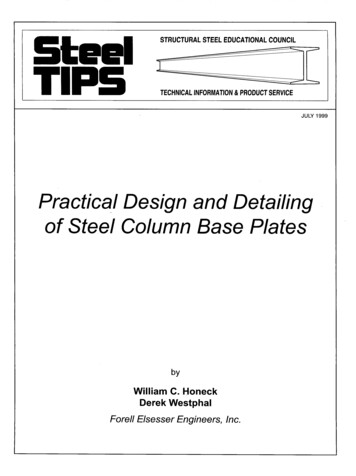
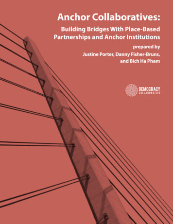
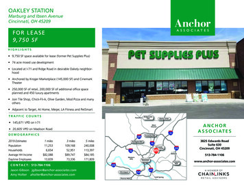
Chapter Two: BackgroundThe main goal of this project is to design a roof tieback system for MIW to fabricate, sell,and install. The goal was accomplished using methods to create an efficient alternative. Thissection addresses background information used to complete the project.Fall Back Protection SystemsThrough-bolt tieback anchors are a permanent anchorage solution that is both safe andpractical. They are used for fall protection and a wide range of suspended access uses (FlexibleLifeline Systems, n.d.). Some of these applications include window cleaning and exteriorbuilding maintenance.Figure 1: Roof tie-back anchorThe figure above is an example of a tie back anchor. It consists of a base plate, which isbolted to a beam on the roof; a metal pipe which has a tall enough height that it extends past roofdecking, keeping the attachment point accessible after the roof is complete; and a top bent roundbar, which a worker’s lifeline is clipped to. OSHA requires the use of fall back protection whenworkers are doing specific tasks or suspended from minimum heights. Some of these tasksinclude exterior maintenance of buildings or window cleaning. The roof anchor provides safetyprotection from falls by clipping a rope descent system to the bent bar on the top of thepermanent roof anchor (Selected OSHA Fall, 2015).13
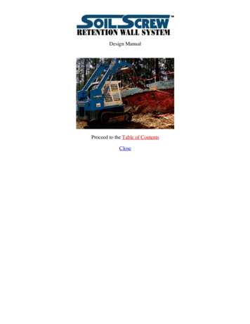
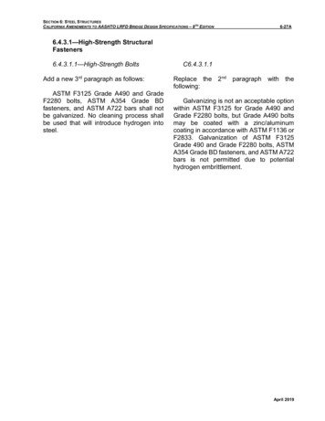
Governing StandardsOSHA is part of the United States Department of Labor, and it was created to assure safeand healthy working conditions for workers by setting and enforcing standards. OSHA works toprovide training, outreach, education and assistance to improve safety in the workplace (AboutOSHA, n. d.).OSHA regulates fall protection systems through certain criteria and practices. Accordingto OSHA’s Regulations (Standards-29 CFR), specifically OSHA 1926.502, anchors must be ableto support at least 5000 pounds per person attached, or have a safety factor of two and usedunder the supervision of a qualified person. OSHA also limits the arresting force to a maximumof 1800 pounds or less, which is not governed by the anchor design but the user’s weight andlifeline length. OSHA has specified a maximum arresting force, versus a minimum, to set largestforce the lifeline and worker would experience in the case of a fall (Selected OSHA Fall, 2015).The American National Standards Institute (ANSI) focuses on strengthening the United Statesmarketplace compared to the global economy while assuring the safety and health of consumers(About ANSI). ANSI has the same roof anchor standards as OSHA according to ANSI/ASSEZ359.0 of the American Society of Safety Engineer’s ANSI/ASSE Z359 Fall Protection Code(Version 3.0)Structural DesignA major part of this project is the structural analysis. The structural components thatdefine the design affect the strength and efficiency of the anchor. Some of these componentsinclude the chosen materials, which affect strength and sustainability.Benchmarked DesignThe designs presented in this project are based off a roof anchor previously produced byMIW Corporation. The design was prepared by Olsen Engineers Inc. in October 2014.14
Figure 2: Tie-down Anchor designed by Olsen EngineersThis design, shown in Figure 2, consisted of a 1.75’ tall 3” diameter schedule 80 pipedirectly welded to a supporting beam. A 0.75” diameter stainless steel bent round bar waswelded to a cap plate which was welded to the top of the pipe. Although none of the designspresented are identical to the original design, the design approach used by Olsen Engineerscreated the framework for the design process in this project.MaterialsCarbon steel is the lowest cost option but offers the least value for sustainability due to itssusceptibility to rust. There are other metal options that do not have this problem. Stainless steelis protected against rust and corrosion, providing better sustainability. Stainless steel has a higheroverall durability with resistance to fire damage, decreasing maintenance cost. Stainless steelalso has a higher ultimate strength than carbon steel, shown in Table 1; however, it is much moreexpensive (Wenzel Metal Spinning, n.d.).15
Table 1: Ultimate and Yield Strength of Carbon vs. Stainless Steel , values based on AISC Table2-4MaterialYield StrengthUltimate StrengthASTM A53 Grade B Carbon Steel35 ksi60 ksiASTM A240: 316 Stainless Steel30 ksi75 ksiAnother option is galvanized steel. Hot dipped galvanizing carbon steel has a smalladditional cost but gives the steel the protection it needs from corrosion with a layer of zinccovering all surfaces. However, welding materials that have already been galvanized can create apoisonous gas due to the reaction between the zinc and the copper (Wenzel Metal Spinning). Thesafety concerns to the welders and expense of safety precautions have to been taken into accountwhen choosing or not choosing a design with galvanized members.SustainabilityLeadership in Energy & Environmental Design (LEED) provides a framework for creatingand maintaining green building designs through the design, construction and operation processes(About LEED, 2015). LEED applies to all building types such as residential, educational, retail,hospitality, healthcare, and existing buildings. Many construction projects strive to becomeLEED certified by fulfilling a list of criteria which involve achieving high performance in areasof human and environmental health.One of the main goals of LEED is to reduce material waste. The addition of permanent roofanchors to a building is applying the idea of reusing materials for multiple purposes, versus usingtemporary supports each time a lifeline is needed.Another way to keep material waste low is ordering the pipes and bent bars in readilyavailable dimensions. The materials should be ordered in dimensions that can be cut down intothe needed size with the least amount of waste.GeometryThe geometry of the anchor design can greatly affect the strength. For a given appliedload, a reduction in the height of the pipe cause lower moments and therefore stresses on thepipe. Although the reduction is beneficial, the pipe height has to be tall enough that it extends16
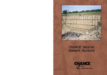
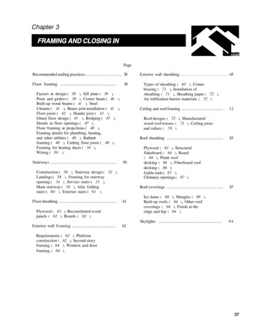
past roof decking; keeping the attachment point accessible after the roof is complete. This isrecommended to be a minimum of one foot.A change in diameter or schedule of the pipe causes changes in the moment of inertia andarea of the cross section, therefore also changing the stresses within the pipe. A change in theradius of the top curved beam affects the bending stresses throughout the curved member. Thesechanges in the geometry also cause changes in the weight which affect the cost of the anchor.Bending Stress of Curved BeamThe bending stress of a beam is equal to My/I when the beam is straight. When a memberis curved, the neutral axis no longer passes through the centroid of the member. The figure belowshows the dimensions of the values used in the calculation.Figure 3: Three radii used in the bending stress calculation of a curved beamThe three radii from the center of curvature, O, are identified as 𝑟, R, and r. The radius 𝑟,is the distance from the center of curvature to the centroid of the member. R is the distance fromO to the neutral axis of the bent member. Due to bending, different strains are caused at the topand bottom of the member, shifting the neutral axis from the centroid of the cross section. The17
neutral axis is the axis in the member where no stress or strain is acting. The third radius, r, is thedistance from the center of curvature to any arbitrary point the stress is being calculated at.The equation used to calculate the location of the neutral axis is the area of the crosssection over the integral of the area in respect to the radius, 𝑅 𝐴𝑑𝐴 ( 𝑟 ). (Hibbeler, 2010).Theintegral can either be calculated by hand or looked up in a table of various geometries.Once R has been found, the bending stress is simple to calculate. The equation of thebending stress in a curved member is 𝜎 𝑀(𝑅 𝑟)𝐴𝑟(𝑟 𝑅). The stress should be found at both the insideand outside of the beam to find which point is critical.RISA3DRISA3D is an engineering computer program used to analyze three-dimensional modelsand to draw designs (Risa3D, 2015). The program allows the user to design with many materialssuch as hot rolled steel, cold rolled steel, masonry, timber, concrete, etc., as well as many shapeslike wide flange beams, hollow structural section columns, pipes, and so many more. Users alsohave the option of placing nodes in specific coordinates and creating their members to extendfrom one node to another. Figure 4 shows the top bent bar of the roof anchor drawn in RISA3D.Figure 4: RISA3D drawing of top bent bar18
Many load types can be applied to designs in the programs. These include nodal, point,moving, surface and distributed loads. Multiple load cases can be programmed to solve thedesign multiple times. The easy-to-use
Originally concentrating on ornamental fences, gates, and rails, the company began to flourish with a number of projects in the Back Bay and Greater Boston Area in the 1970's. In 1980, MIW began fabricating and installing more complex miscellaneous and ornamental steel after purchasing a small fabricating shop in Roslindale, MA. .