Transcription
00032000:9990938: 19990302Model 32000 Series Crane& Model 4490 (Metric Version)Volume 2 - PARTS AND 1A.234SPECIFICATIONS-32000 SERIESSPECIFICATIONS-4490 CRANECRANE REFERENCEREPLACEMENT PARTSGENERAL REFERENCEIOWA MOLD TOOLING CO., INC.BOX 189, GARNER, IA 50438-0189TEL: 515-923-3711TECHNICAL SUPPORT FAX: 515-923-2424MANUAL PART NUMBER 99900938
00032000:9990938: 19980826INTRODUCTIONThis volume deals with information applicable to yourparticular crane. For operating, maintenance andrepair instructions, refer to Volume 1, OPERATION,MAINTENANCE AND REPAIR.We recommend that this volume be kept in a safeplace in the office.This manual is provided to assist you with orderingparts for your IMT crane. It also contains additionalinstructions regarding your particular installation.It is the user s responsibility to maintain and operatethis unit in a manner that will result in the safestworking conditions possible.Warranty of this unit will be void on any part of theunit subjected to misuse due to overloading, abuse,lack of maintenance and unauthorized modifications.No warranty - verbal, written or implied - other thanthe official, published IMT new machinery andequipment warranty will be valid with this unit.In addition, it is also the user s responsibility to beaware of existing Federal, State and Local codes andregulations governing the safe use and maintenanceof this unit. Listed below is a publication that theuser should thoroughly read and understand.ANSI/ASME B30.22ARTICULATING BOOM CRANESThe American Society of Mechanical EngineersUnited Engineering Center345 East 47th StreetNew York, NY 10017Three means are used throughout this manual to gainthe attention of personnel. They are NOTE s,CAUTION s and WARNING s and are defined asfollows:NOTEA NOTE is used to either convey additionalinformation or to provide further emphasis for aprevious point.CAUTIONA CAUTION is used when there is the very strongpossibility of damage to the equipment or prematureequipment failure.WARNINGA WARNING is used when there is the potential forpersonal injury or death.Treat this equipment with respect and service itregularly. These two things can add up to a saferworking environment.Read and familiarize yourself with theIMT OPERATOR’S CRANE SAFETY MANUALbefore operating or performing any maintenanceon your crane.
00032000: 99900938: 199612201-1SECTION 1. 32000 SERIES CRANE SPECIFICATIONSGENERAL SPECIFICATIONS .3PERFORMANCE CHARACTERISTICS . 4POWER SOURCE. 4CYLINDER HOLDING VALVES . 4ROTATION SYSTEM . 4HYDRAULIC SYSTEM .4SELECTED WEIGHTS OF ANCILLARY EQUIPMENT . 4GEOMETRIC CONFIGURATION . 5CAPACITY CHART . 6MINIMUM CHASSIS SPECIFICATIONS . 7
00032000: 99900938: 199612201-2NOTES
00032000: 99900938: 199612201-3SPECIFICATIONS-MODEL 32027 CRANEGENERAL SPECIFICATIONS3H*CRANE RATING (ANSI B30.22)323,750 ft lbs*MAXIMUM CRANE RATING323,750 ft lbsHORIZONTAL REACHfrom centerline of rotation30'-0'’HYDRAULIC EXTENSION55'’/60'’/60'’VERTICAL REACHfrom mounting surface37'-3'’VERTICAL REACHfrom ground / 43'’ frame ht.40'-10'’CRANE WEIGHTOUTRIGGER SPAN - base mounted15,160 lbsOUTRIGGER SPAN - AUXILIARY(required)18'-0'’14'-0'’OUTRIGGER PADS16'’ x 16'’OUTRIGGER PADS-AUXILIARY14'’ x 14'’CRANE STORAGE HEIGHTfrom mounting surface9'-11'’CRANE STORAGE HEIGHTfrom ground/43'’ frame ht.13'-6'’**MOUNTING SPACE REQUIRED70'’ROTATIONAL TORQUE38320 ft-lbsOPTIMUM PUMP CAPACITY20 GPMSYSTEM OPERATING PRESSURE2500 PSIOIL RESERVOIR CAPACITY60 U.S. GallonsHOOK APPROACH - HORIZONTALfrom centerline of rotation2'-11'’HOOK APPROACH - VERTICALfrom mounting surface9'-1'’***HORIZONTAL CTR OF GRAVITYfrom centerline of rotation towards outriggers6'’***VERTICAL CTR OF GRAVITYfrom mounting surface3'-6'’* Maximum Crane Rating (ft-lbs) is defined as that rated load (lbs) which when multiplied by its respectivedistance (ft) from centerline of rotation gives the greatest ft-lb value.ANSI B30.22 Crane Rating (ft-lbs) With all extensions retracted and inner plus outer boom in a horizontalposition, rated load (lbs) X respective distance (ft) from centerline of rotation nominal ft-lb value.** Mast will swing within the confines of the crane base requiring no addition space behind the cab.*** Crane in stowed position.
00032000: 99900938: 199612201-4PERFORMANCE CHARACTERISTICSROTATION:INNER BOOM ELEVATION:OUTER BOOM ARTICULATION:TELESCOPIC EXTENSIONS:1st Stage2nd Stage3rd StagePOWER-OUT OUTRIGGER:POWER-DOWN OUTRIGGER:400 -48 to 74 140 60 seconds46 seconds45 seconds55'’60'’60'’60'’26'’54 seconds32 seconds14 seconds9 seconds14 secondsPOWER SOURCEHydraulic piston pump and PTO application. Other standard power sources of the closed-center, variable displacement and load sensing type may be utilized. Minimum horsepower required is 35 H.P.CYLINDER HOLDING VALVESThe holding sides of all standard cylinders are equipped with integral-mounted holding or counter-balance valves toprevent sudden cylinder collapse in case of hose or other hydraulic failure. The power-out and power-downoutrigger cylinders have positive, pilot operated holding valves that open only upon command.The counter-balancevalve serves several functions. First, it is a holding valve. Secondly, it is so constructed that it will control thelowering function and allow that motion to be feathered while under load. Finally, if a hose breaks, the only oil losswill be that in the hose.ROTATION SYSTEMRotation of the crane is accomplished through a turntable bearing, powered by two high torque hydraulic disc-valvemotors through two planetary gear boxes. A fail-safe, spring-loaded brake is an integral part of each planetarygear box which provides rotational and parking brake action. Total gear reduction is 99:1.HYDRAULIC SYSTEMThe hydraulic system is a closed center, load sensing, standby-pressure system providing 20 GPM optimum oil flowat 2500 PSI. Stack type control valve with dual operational control handles located at both sides of the crane forall lift, telescope and swing functions is standard. Single control lever for each outrigger function, located on thesame side as the outrigger, is standard. System includes hydraulic oil reservoir, suction and return line filters,closed center, load sensing control valve and a variable displacement radial piston pump.SELECTED WEIGHTS OF ANCILLARY EQUIPMENTAUXILIARY OUTRIGGERS18' SUB-FRAMEPUMP & PTOMOUNTING HARDWAREOIL RESERVOIROIL (60 gallons)IMT reserves the rightto change specificationsand design without notice.1770 lbs1800 lbs140 lbs520 lbs190 lbs420 lbs
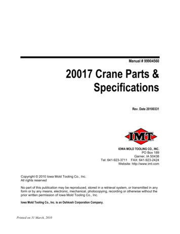
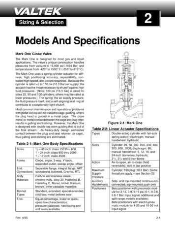
00032000: 99900938: 199612201-5GEOMETRIC CONFIGURATION
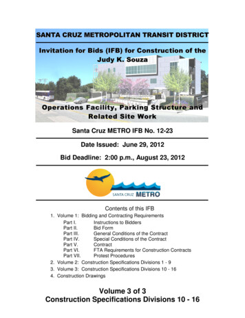
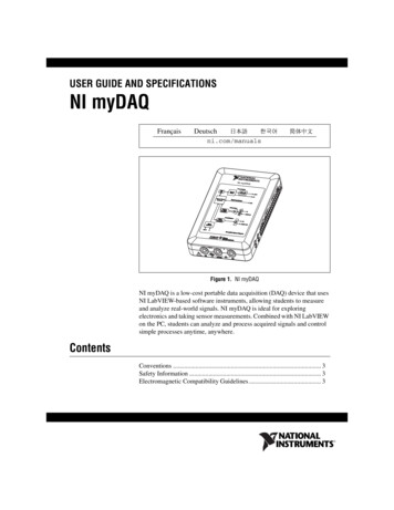
00032000: 99900938: 199701211-6CAPACITY CHART
00032000: 99900938: 199612201-7MINIMUM CHASSIS SPECIFICATIONSFor Standard 32000 Series CraneCRANE MOUNTCRANE WORKING AREACHASSIS STYLEFRONT AXLE RATING (GAWR)REAR AXLE RATING (GAWR)WHEELBASECAB-TO-AXLEFRAME HEIGHT FROM GROUNDRBMFRAME SECTION MODULUSFRAME YIELD STRENGTHBehind Cab360 Conventional Cab20000 lbs40000 lbs Tandem Axle236'’156'’43'’ Maximum5,060,000 in-lbs46in3110,000 PSITo maintain vehicle stability, it will be necessary to provide auxiliary outriggers which have, at a minimum, 14'-0' span. A subframe/torsion box must be used to tie the auxiliary outriggers to the crane. For each applicationcontact IMT for a weight distribution and stability analysis.NOTES:1. GAWR means Gross Axle Weight Rating and is dependent on all components of the vehicle such as axles,tires, wheels, springs, brakes, steering and frame strength meeting the manufacturer s recommendations.Always specify GAWR when purchasing a truck.2. Minimum axle requirements may increase with use of diesel engines, longer wheelbase or service bodies.Contact the factory for further information.3. Weight distribution calculations are required to determine final axle loading.4. All chassis and crane combinations must be stability tested to ensure stability per ANSI B30.22
00032000: 99900938: 199612201-8IOWA MOLD TOOLING CO., INC.BOX 189, GARNER, IA 50438-0189TEL: 515-923-3711FAX: 515-923-2424
00032000: 99900938: 199612201-1SECTION 1A. MODEL 4490 CRANE SPECIFICATIONSGENERAL SPECIFICATIONS . 3PERFORMANCE CHARACTERISTICS . 4POWER SOURCE. 4CYLINDER HOLDING VALVES . 4ROTATION SYSTEM . 4HYDRAULIC SYSTEM . 4SELECTED WEIGHTS OF ANCILLARY EQUIPMENT . 4GEOMETRIC CONFIGURATION . 5CAPACITY CHART . 6
00032000: 99900938: 199612201-2NOTES
00032000: 99900938: 199612201-3SPECIFICATIONS-MODEL 4490 CRANEGENERAL SPECIFICATIONSCRANE RATING44 ton-metersHORIZONTAL REACHfrom centerline of rotation9.14mHYDRAULIC EXTENSION140/152/152cmVERTICAL REACHfrom mounting surface11.36mVERTICAL REACHfrom ground / 1.09m frame ht.12.45m*BASE CRANE WEIGHT5875 kgOUTRIGGER SPAN - base mounted5.49mOUTRIGGER SPAN - AUXILIARY(required)4.27mOUTRIGGER PADS40 x 40cmOUTRIGGER PADS-AUXILIARY35 x 35cmCRANE STORAGE HEIGHTfrom mounting surface3.02mCRANE STORAGE HEIGHTfrom ground/1.09m frame ht.4.11m**MOUNTING SPACE REQUIRED1.78mROTATIONAL TORQUE5300 kg-mOPTIMUM PUMP CAPACITY76 liters/minSYSTEM OPERATING PRESSURE172 barOIL RESERVOIR CAPACITY228 litersHOOK APPROACH - HORIZONTALfrom centerline of rotation89cmHOOK APPROACH - VERTICALfrom mounting surface2.77m***HORIZONTAL CTR OF GRAVITYfrom centerline of rotation towards outriggers15cm***VERTICAL CTR OF GRAVITYfrom mounting surface107cm* Without outriggers, hydraulic oil reservoir and mounting accessories.** Mast will swing within the confines of the crane base requiring no addition space behind the cab.*** Crane in stowed position.
00032000: 99900938: 199612201-4PERFORMANCE CHARACTERISTICSROTATION:INNER BOOM ELEVATION:OUTER BOOM ARTICULATION:TELESCOPIC EXTENSIONS:1st Stage2nd Stage3rd StagePOWER-OUT OUTRIGGER:POWER-DOWN OUTRIGGER:400 /6.98 rad-0.84 to 1.29 rad2.44 rad60 seconds46 seconds45 seconds140cm152cm152cm152cm66cm54 seconds32 seconds14 seconds9 seconds14 secondsPOWER SOURCEHydraulic piston pump and PTO application. Other standard power sources of the closed-center, variable displacement and load sensing type may be utilized. Minimum horsepower required is 35 H.P.CYLINDER HOLDING VALVESThe holding sides of all standard cylinders are equipped with integral-mounted holding or counter-balance valves toprevent sudden cylinder collapse in case of hose or other hydraulic failure. The power-out and power-downoutrigger cylinders have positive, pilot operated holding valves that open only upon command.The counter-balancevalve serves several functions. First, it is a holding valve. Secondly, it is so constructed that it will control thelowering function and allow that motion to be feathered while under load. Finally, if a hose breaks, the only oil losswill be that in the hose.ROTATION SYSTEMRotation of the crane is accomplished through a turntable bearing, powered by two high torque hydraulic discvalvemotors through two planetary gear boxes. A fail-safe, spring-loaded brake is an integral part of each planetary gear box which provides rotational and parking brake action. Total gear reduction is 99:1.HYDRAULIC SYSTEMThe hydraulic system is a closed center, load sensing, standby-pressure system providing 76 liters/minute optimumoil flow at 172 bar. Stack type control valve with dual operational control handles located at both sides of thecrane for all lift, telescope and swing functions is standard. Single control lever for each outrigger function, locatedon the same side as the outrigger, is standard. System includes hydraulic oil reservoir, suction and return linefilters, closed center, load sensing control valve and a variable displacement radial piston pump.SELECTED WEIGHTS OF ANCILLARY EQUIPMENTCRANE OUTRIGGERSAUXILIARY OUTRIGGERS5.5m SUBFRAMEPUMP & PTOMOUNTING HARDWAREHYDRAULIC OIL RESERVOIR230 LITERS OF HYDRAULIC OILIMT reserves the rightto change specificationsand design without notice.1000 kg803 kg816 kg64 kg238 kg85 kg193 kg
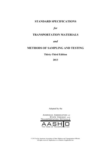
00032000: 99900938: 199612201-5GEOMETRIC CONFIGURATION
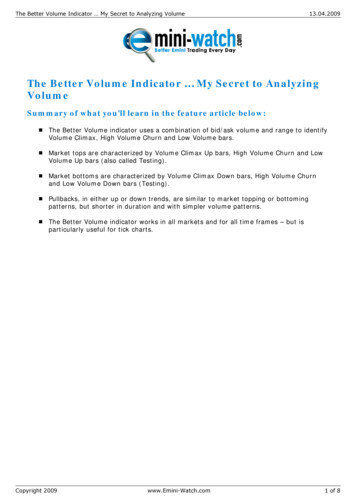
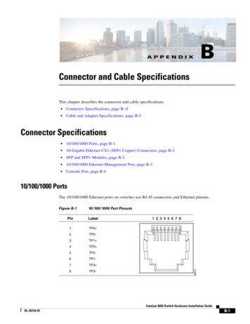
00032000: 99900938: 199701211-6CAPACITY CHART
00032000:99900938: 199612202-1SECTION 2. 32000/4490 CRANE REFERENCEMAJOR CRANE ASSEMBLIES . 3WELDMENT PART NUMBER LOCATIONS . 4GREASE ZERK LOCATIONS & LUBRICANT REQUIREMENTS .
OUTRIGGER PADS 16'’ x 16'’ OUTRIGGER PADS-AUXILIARY 14'’ x 14'’ CRANE STORAGE HEIGHT 9'-11'’ from mounting surface CRANE STORAGE HEIGHT 13'-6'’ from ground/43'’ frame ht. **MOUNTING SPACE REQUIRED 70'’ ROTATIONAL TORQUE 38320 ft-lbs OPTIMUM PUMP CAPACITY 20 GPM SYSTEM OPERATING PRESSURE 2500 PSI OIL RESERVOIR CAPACITY 60 U.S. Gallons HOOK