Transcription
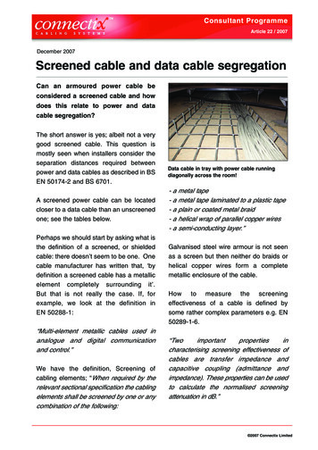
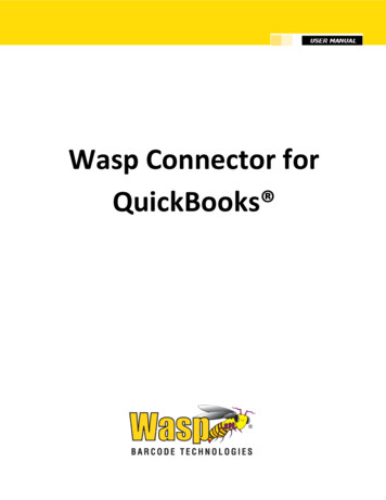
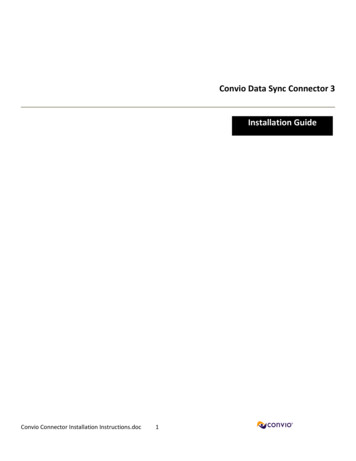
BA P P E N D I XConnector and Cable SpecificationsThis chapter describes the connector and cable specifications. Connector Specifications, page B-1l Cable and Adapter Specifications, page B-5Connector Specifications 10/100/1000 Ports, page B-1 10-Gigabit Ethernet CX1 (SFP Copper) Connectors, page B-2 SFP and SFP Modules, page B-2 10/100/1000 Ethernet Management Port, page B-3 Console Port, page B-410/100/1000 PortsThe 10/100/1000 Ethernet ports on switches use RJ-45 connectors and Ethernet pinouts.10/100/1000 Port PinoutsPinLabel1TP0 2TP0-3TP1 4TP2 5TP2-6TP1-7TP3 8TP3-1 2 3 4 5 6 7 860915Figure B-1Catalyst 3650 Switch Hardware Installation GuideOL-29734-01B-1
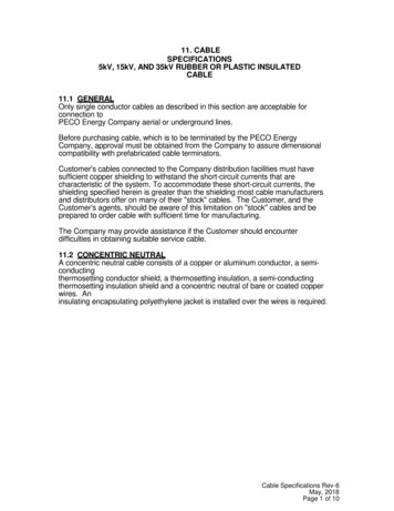
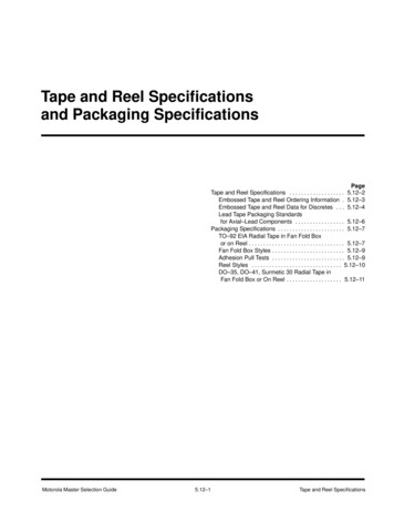
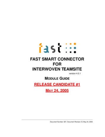
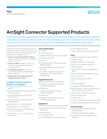
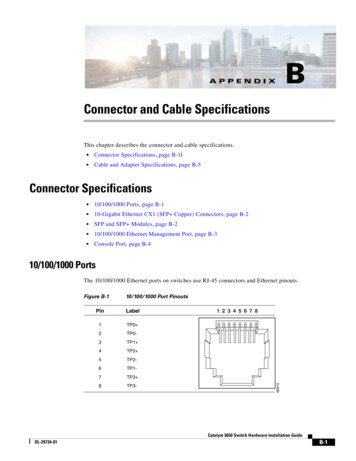
Appendix BConnector and Cable SpecificationsConnector Specifications10-Gigabit Ethernet CX1 (SFP Copper) ConnectorsThe 10-Gigabit Ethernet electrical modules use CX1 copper connectors similar to the one shown inFigure B-2.NoteWhen ordering or using CX1 cables, ensure that the version identifier is 2 or higher.The 10-Gigabit Ethernet optical modules use the connectors shown in Figure B-3 and Figure B-4.10-Gigabit Ethernet CX1 Copper Connector (example)278541Figure B-2SFP and SFP ModulesFigure B-3, Figure B-4, and Figure B-5 show the SFP module connectors.The switch supports the SFP module patch cable, a 0.5-meter, copper, passive cable with SFP moduleconnectors at each end (Figure B-6). This cable can be used (only with 1-Gigabit Ethernet SFP ports) toconnect two Catalyst 3650 switches in a cascaded configuration.Duplex LC Cable Connector58476Figure B-3Catalyst 3650 Switch Hardware Installation GuideB-2OL-29734-01
Appendix BConnector and Cable SpecificationsConnector SpecificationsSimplex LC Cable ConnectorFigure B-5Copper SFP Module RJ-45 Connector57834Figure B-4Label1TP0 2TP0-3TP1 4TP2 5TP2-6TP1-7TP3 8TP3-SFP Module Patch Cable126809Figure B-61 2 3 4 5 6 7 860915Pin10/100/1000 Ethernet Management PortThe 10/100/1000 Ethernet management port uses RJ-45 connectors with Ethernet pinouts. Figure B-7shows the pinouts.Catalyst 3650 Switch Hardware Installation GuideOL-29734-01B-3
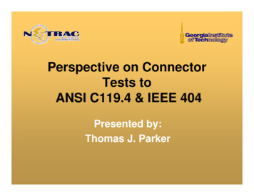
Appendix BConnector and Cable SpecificationsConnector Specifications10/100 Port PinoutsPinLabel1RD 2RD-3TD 4NC5NC6TD-7NC8NC1 2 3 4 5 6 7 8H5318Figure B-7Console PortThe switch has two console ports: a USB 5-pin mini-Type B port on the front panel (see Figure B-8) andan RJ-45 console port on the rear panel.USB Mini-Type B Port345492Figure B-8The USB console port uses a USB Type A to 5-pin mini-Type B cable, shown in Figure B-9. The USBType A-to-USB mini-Type B cable is not supplied. You can order an accessory kit (partnumber 800-33434) that contains this cable.USB Type A-to-USB 5-Pin Mini-Type B Cable345493Figure B-9The RJ-45 console port uses an 8-pin RJ-45 connector (See Table B-2 and Table B-3.) The suppliedRJ-45-to-DB-9 adapter cable is used to connect the console port of the switch to a console PC. You needto provide a RJ-45-to-DB-25 female DTE adapter if you want to connect the switch console port to aCatalyst 3650 Switch Hardware Installation GuideB-4OL-29734-01
Appendix BConnector and Cable SpecificationsCable and Adapter Specificationsterminal. You can order a kit (part number ACS-DSBUASYN ) containing that adapter. For console portand adapter pinout information, see Table B-2 and Table B-3.Cable and Adapter Specifications StackWise Cables, page B-5 StackWise Adapters, page B-6 StackWise Adapter Blanks, page B-7 SFP and SFP Module Cable Specifications, page B-7 Four Twisted-Pair Cable Pinouts, page B-8 Two Twisted-Pair Cable Pinouts, page B-8 Identifying a Crossover Cable, page B-9 Console Port Adapter Pinouts, page B-9StackWise CablesFigure B-10 shows a StackWise stacking cable.StackWise Stacking Cable347676Figure B-10You can order these StackWise cables (nonhalogen) from your Cisco sales representative: STACK-T2-50CM (0.5-meter cable) STACK-T2-1M (1-meter cable) STACK-T2-3M (3-meter cable)Catalyst 3650 Switch Hardware Installation GuideOL-29734-01B-5
Appendix BConnector and Cable SpecificationsCable and Adapter SpecificationsStackWise Cables Minimum Bend Radius and Coiled DiameterTable B-1 specifies the minimum bend radius and coiled diameter for each StackWise cable.Table B-1StackWise Cables Minimum Bend Radius and Coiled DiameterCable Part NumberCable LengthMinimum Bend RadiusMinimum Coiled DiameterSTACK-T2-50CM1.64 ft (0.5 m)2.60 in. (66 mm)5.20 in. (132 mm)STACK-T2-1M3.28 ft (1.0 m)2.60 in. (66 mm)5.20 in. (132 mm)STACK-T2-3M9.84 ft (3.0 m)3.58 in. (91 mm)7.17 in. (182 mm)StackWise AdaptersA StackWise adapter must be installed in the stacking port to enable stacking. The StackWise cableconnects to the StackWise adapter in the stacking port. For switches ordered with stacking, theStackWise adapters are preinstalled.If the switches are not ordered with stacking, the adapters must be ordered separately and installed. Youcan order a StackWise adapter as part of a StackWise stacking upgrade kit (part numberC3650-STACK-KIT ), that contains two adapters and a 0.5 m StackWise cable.Locating the StackWise Adapter Serial NumberIf you contact Cisco Technical Assistance regarding a StackWise adapter, you need to know the serialnumber. See Figure B-11 to find the serial number.Location of the Serial Number on the StackWise Adapter347806, 781-00796-01Figure B-11SN: AAANNNNXXXXCatalyst 3650 Switch Hardware Installation GuideB-6OL-29734-01
Appendix BConnector and Cable SpecificationsCable and Adapter SpecificationsStackWise Adapter BlanksA StackWise adapter blank is installed in the stacking port if stacking is not specified at the time ofordering the switch. The StackWise adapter blank is screwed into the stacking port and must be removedand replaced by a StackWise adapter if the port is to be used for stacking. Figure B-12 shows aStackWise adapter blank.Figure B-12StackWise Adapter Blank1347816231StackWise adapter blank2Assembly screw3Cisco labelSFP and SFP Module Cable SpecificationsEach port must match the wave-length specifications on each end of the cable, and the cable must notexceed the stipulated cable length. Copper 1000BASE-T SFP module transceivers use standard fourtwisted-pair, Category 5 cable at lengths up to 328 feet (100 meters).For cabling specifications, refer to the Cisco Transceiver Modules data sheet ps5455/products data sheets list.htmlCatalyst 3650 Switch Hardware Installation GuideOL-29734-01B-7
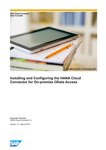
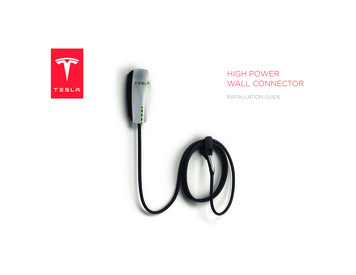
Appendix BConnector and Cable SpecificationsCable and Adapter SpecificationsFour Twisted-Pair Cable PinoutsRouter or PC1 TPO 1 TP1 2 TPO-2 TP1-3 TP1 3 TPO 6 TP1-6 TPO-4 TP2 4 TP3 5 TP2-5 TP3-7 TP3 7 TP2 8 TP3-8 TP2-Figure B-1465272SwitchFour Twisted-Pair Straight-Through Cable SchematicFour Twisted-Pair Crossover Cable SchematicSwitchSwitch1 TP0 1 TP0 2 TP0-2 TP0-3 TP1 3 TP1 6 TP1-6 TP1-4 TP2 4 TP2 5 TP2-5 TP2-7 TP3 7 TP3 8 TP3-8 TP3-65274Figure B-13Two Twisted-Pair Cable PinoutsTwo Twisted-Pair Straight-Through Cable SchematicSwitchRouter or PC3 TD 6 TD–3 RD 6 RD–1 RD 2 RD–1 TD 2 TD–H5578Figure B-15Catalyst 3650 Switch Hardware Installation GuideB-8OL-29734-01
Appendix BConnector and Cable SpecificationsCable and Adapter SpecificationsTwo Twisted-Pair Crossover Cable SchematicSwitchSwitch3 TD 6 TD–3 TD 6 TD–1 RD 2 RD–1 RD 2 RD–H5579Figure B-16Identifying a Crossover CableTo identify a crossover cable, hold the cable ends side-by-side, with the tab at the back. The wireconnected to the pin on the outside of the left plug should be the same color as the wire connected to thepin on the outside of the right plug. (See Figure B-17.)Figure B-17Identifying a Crossover CablePin 1 on one connector andpin 8 on the other connectorshould be the same color.Pin 1H10632Pin 8Console Port Adapter PinoutsThe console port uses an 8-pin RJ-45 connector, which is described in Table B-2 and Table B-3. If youdid not order a console cable, you need to provide an RJ-45-to-DB-9 adapter cable to connect the switchconsole port to a PC console port. You need to provide an RF-45-to-DB-25 female DTE adapter if youwant to connect the switch console port to a terminal. You can order a kit with an adapter (partnumber ACS-DSBUASYN ). For console port and adapter pinout information, see Table B-2 andTable B-3.Table B-2 lists the pinouts for the console port, the RF-45-to-DB-9 adapter cable, and the console device.Table B-2Console Port Signaling Using a DB-9 AdapterSwitch ConsolePort (DTE)RJ-45-to-DB-9Terminal AdapterConsoleDeviceSignalDB-9 PinSignalRTS8CTSDTR6DSRTxD2RxDCatalyst 3650 Switch Hardware Installation GuideOL-29734-01B-9
Appendix BConnector and Cable SpecificationsCable and Adapter SpecificationsTable B-2Console Port Signaling Using a DB-9 Adapter (continued)Switch ConsolePort (DTE)RJ-45-to-DB-9Terminal AdapterConsoleDeviceSignalDB-9 PinSignalGND5GNDGND5GNDRxD3TxDDSR4DTRCTS7RTSTable B-3 lists the pinouts for the console port, RJ-45-to-DB-25 female DTE adapter, and theconsole device.NoteThe RJ-45-to-DB-25 female DTE adapter is not supplied with the switch. You can order a kit with theadapter (part number ACS-DSBUASYN ) from Cisco.Table B-3Console Port Signaling Using a DB-25 AdapterSwitch ConsolePort (DTE)RJ-45-to-DB-25Terminal AdapterConsoleDeviceSignalDB-25 DDSR20DTRCTS4RTSCatalyst 3650 Switch Hardware Installation GuideB-10OL-29734-01
Catalyst 3650 Switch Hardware Installation Guide OL-29734-01 Appendix B Connector and Cable Specifications Connector Specifications Figure B-7 10/100 Port Pinouts Console Port The switch has two console ports: a USB 5-pin mini-Type B port on the front panel (see Figure B-8) and an RJ-45 console port on the rear panel. Figure B-8 USB Mini-Type B Port