Transcription
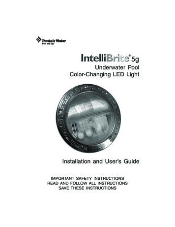
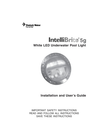
INTELLIBRITE 5GWHITE AND COLOR POOL AND SPA LIGHTSINSTALLATION ANDUSER’S GUIDEIMPORTANT SAFET Y INSTRUCTIONSREAD AND FOLLOW ALL INSTRUCTIONSSAVE THESE INSTRUCTIONSINTELLIBRITE 5G White Pool and Spa LED Light Installation and User’s Guide
IITechnical Support: Phone: (800) 831-7133 - Fax: (800) 284-4151Web site: www.pentair.comContentsIMPORTANT WARNING AND SAFETY INSTRUCTIONS. iii-ivIntelliBrite 5G Pool and Spa Lights Overview . 1Operating IntelliBrite Pool and Spa lights using a wall switch (12 VAC) . 1Using an External Transformer for Multiple IntelliBrite 12 VAC Lights .1Powering on IntelliBrite 5G Lights . 2Selecting a light show mode or fixed color (Color Lights) . 2Using an IntelliBrite Color Light Controller . 2Replacing the IntelliBrite 5G Pool and Spa Light Fixture(in an existing pool/after electrical requirements are met) . 3/5IntelliBrite 5G Pool and Spa Light Fixture Installation(new pool construction - GFCI Installation Requirements (USA) . 6/7IntelliBrite 5G Pool and Spa Light Fixture Installation(new pool construction (Canada) . 7Junction Box/GFCI Installation Requirements (Canada) . 8Installing the IntelliBrite 5G Pool and Spa Light Fixture(after electrical requirements are met) . 9IntelliBrite 5G Pool Light (12 V) Fuse Harness Replacement Overview . 11Replacing the IntelliBrite 5G Pool Light Circuit Board Assy (existing pool).12Installing the IntelliBrite Light Assembly, new gasket/Uni-tension Wire Clamp .15Wide and Narrow Angle Lens Adjustment/Part Numbers .19/20Replacing the IntelliBrite Spa Light Fixture (existing pool) . 21IntelliBrite 5G Spa Light Replacement Kit Part Numbers . 25Before Installing luminaries read the following:Always install a new Uni-Tension Wire Clamp assemblyand Lens Gasket (see page 19), when reassembling the lightassembly. Failure to do so may permit water to leak into the assembly whichcould cause; (a) an electrical hazard resulting in death or serious injury to poolusers, installer, or others due to electrical shock, or (b) breakage of the lampor lens, which likewise could result in serious injury to pool user, installers, orbystanders, or in damage to property.FOR 12 VAC LUMINARIES: ALWAYS USE A SEPARATE STEP DOWNTRANSFORMER TO POWER LUMINARIES. SEE DIAGRAM ON PAGE 7. Note:Connect all three wires to the corresponding circuit wires in the JunctionBox (black wire to power, white wire to common, and green wire to ground).12 VAC LUMINARIES SPECIFICATION: 50/60 Hz. REPLACE ANY CRACKEDPROTECTIVE SHIELD (CRACKED LENS) WITH NEW LENS AND GASKET.THE INTELLIBRITE 5G LED POOL LIGHT AND SPALIGHT CANNOT BE USED ON A DIMMER CIRCUIT.USING A DIMMER SWITCH WILL RESULT IN PERMANENTDAMAGE TO THE LIGHT.P/N 620278 Rev C - 2/2019INTELLIBRITE 5G Pool and Spa Lights Installation and User’s Guide
IIIIMPORTANT WARNING AND SAFETY INSTRUCTIONSSERIOUS BODILY INJURY OR DEATH CAN RESULT IF THIS LIGHTIS NOT INSTALLED AND USED CORRECTLY.INSTALLERS, POOL OPERATORS AND POOL OWNERS MUSTREAD THESE WARNINGS AND ALL INSTRUCTIONS BEFOREUSING THE POOL AND/OR SPA LIGHT.Most states and local codes regulate the construction, installation,and operation of public pools and spas, and the construction ofresidential pools and spas. It is important to comply with these codes, many of whichdirectly regulate the installation and use of this product. Consult your local building andhealth codes for more information.IMPORTANT NOTICE - Attention Installer: This Installation and User’sGuide (“Guide”) contains important information about the installation, operationand safe use of this underwater pool and spa light. This Guide should be givento the owner and/or operator of this equipment.Before installing this product, read and follow all warning noticesand instructions in this Guide. Failure to follow warnings andinstructions can result in severe injury, death, or property damage.Call (800) 831-7133 for additional free copies of these instructions. Please refer to www.pentairpool.com for more information related to this products.RISK OF ELECTRICAL SHOCK OR ELECTROCUTION:THE INTELLIBRITE POOL AND SPA LIGHT REQUIRE HIGHVOLTAGE WHICH CAN SHOCK, BURN, OR CAUSE DEATH.BEFORE WORKING ON POOL AND SPA LIGHTS alwaysdisconnect power to the pool and/or spa lights at the circuitbreaker from the light before servicing the light. Failure to do socould result in death or serious injury to service person, poolusers or others due to electric shock.This underwater light must be installed by a licensed or certified electrician or aqualified pool professional in accordance with the current National Electrical Code(NEC), NFPA 70 or the Canadian Electrical Code (CEC), CSA C22.1. All applicablelocal installation codes and ordinances must also be adhered to. Improper installationwill create an electrical hazard which could result in death or serious injury to poolusers, installers or others due to electrical shock, and may also cause damageto property. Always disconnect the power to the pool light at the circuit breakerbefore servicing the light. Failure to do so could result in death or serious injury toserviceman, pool users or others due to electrical shock.Important Safety Information for Pentair Water Pool and Spa Nicheand Light Installation All Niche and Light installations must conform with all codes. If local codesmandate a cord seal, use Pentair Water Pool and Spa plastic niches(P/N 79206600 and P/N 79206700) and Cord Seal Kit (P/N 670044). Under no circumstances replace lights by splicing wire under water or behindniche.READ AND FOLLOW ALL INSTRUCTIONS IN THIS MANUAL.INTELLIBRITE 5G Pool and Spa Lights Installation and User’s Guide
IVIMPORTANT WARNING AND SAFETY INSTRUCTIONSRISK OF ELECTRIC SHOCK AND INJURY. USE ONLY THEINSTALLATION METHOD SPECIFIED BELOW.Location ofLuminaire UseSwimming Pooland SpaPentair Water Pool and Spa FountainFixture* (P/N 560001 and P/N 560000)Wet-Niche Swimming Pool(or Spa) Luminaire (Light)Required Installation MethodFountainWet-Niche Submersible Luminaire (Light) Fixture Housing (Forming Shell) orswimming Pool (or Spa) Luminair (Light) Fountain Fixture StandFixture Housing (Forming Shell) ONLY.DO NOT USE Fountain Fixture Stand.(*) Note: Wet-niche luminaires complying with requirements for both uses may bareboth the Listed Wet-Niche Submersible Luminaires UL Mark. A luminaire not bearing thecorresponding UL Listing Mark is not considered by UL to have been produced under UL’sListing and Follow-Up Service for the associated usage location.CAUTION - The IntelliBrite 5G Light fixture must only be used with Pentair Water Pooland Spa fixture housings (niches). If the IntelliBrite light fixture is installed into otherniches, the installation will not carry U.L. approval and will void all warranties.NOTICE: The external flexible cable or cord of this luminaire cannot be replaced; ifthe cord is damaged, the luminaire shall be destroyed.For countries in compliance with International ElectromechnicalCommission (IEC) regulatory standards: The light fixture mustbe installed by a licensed or certified electrician or a qualified pool service person, inaccordance with IEC 364-7-702 and all applicable local codes and ordinance. Improperinstallation will create an electrical hazard, which could result in death or serious injuryto pool user, installer or other due to electrical shock and may also cause damage to theproperty.Salt is an inherently corrosive material. While the levels of salt requiredfor proper operation of an electronic chlorine generator are relatively lowwhen compared to sea water and other salt solutions, placing any amount of salt in yourpool increases the likelihood of corrosion or other deterioration of pool equipment and anysurfaces used in and around your pool. Metal parts and certain natural and man-madesurfaces are particularly susceptible to corrosion and deterioration when used in andaround salt water pools. Pentair does not represent or otherwise guarantee that the properuse of an electronic chlorine generator will prevent corrosion or other deterioration of poolequipment and any surfaces used in and around your pool. Consult your experiencedpool professional, who should be able to advise you on the proper material selection,installation techniques for those materials, and the proper use, care and maintenance ofthose materials for your specific pool type and location in order to minimize the corrosionand deterioration that is inherent in and around salt water pools.POOL AND SPA FIXED LUMINARIES: Follow these guidelines when installing,replacing or repairing Pentair Aquatic Systems Pool and Spa fixed luminaries:REPLACE ANY CRACKED PROTECTIVE SHIELD (CRACKED LENS) WITH NEWLENS AND GASKET. FOR MORE INFORMATION SEE PAGE 11.FOR LIGHT OPERATION, ONLY USE A SAFETY ISOLATION TRANSFORMER.CAUTION! Luminaires not suitable for direct mountingon normally flammable surfaces (suitable ONLY formounting on non-combustible surfaces.Fixed pool and spa luminaries specification:12 VAC 50/60 Hz - 120VAC,50/60 Hz.Surface Mount
1IntelliBrite 5G Pool and Spa Lights OverviewThis manual describes how to install the IntelliBrite 5G white and color pool light and theIntelliBrite 5G white and color spa light.The IntelliBrite 5G white light provides a brilliant white light for a spectacular effect inyour pool and spa. The IntelliBrite 5G white light lens geometry (pool light only) providesa choice between two light beam shapes; wider coverage with less intensity, or narrowercoverage with more intensity.The IntelliBrite 5G color light provides brilliant vivid multi-colors with spectacular effectsfor your pool and spa. Choose one of the seven pre-programmed color light shows orselect one of the five fixed colors to create virtually endless range of dramatic underwaterlighting effects for a spectacular effect in your pool and spa.Operating Pool and Spa Lights Using a Wall Switch (12 VAC)IntelliBrite 5G pool and spa lights can be manually controlled using a standard wall-mountlight switch. Multiple IntelliBrite lights can be connected via a junction box to a singleswitch so that all lights can be switched on and off together. IntelliBrite lights can also beautomatically controlled via Pentair IntelliTouch , EasyTouch and SunTouch ControlSystems. Note: Multiple IntelliBrite 5G pool/spa lights can also be controlled usingthe IntelliBrite Controller, for more information see page 2.Using an External Transformer for Multiple IntelliBrite 12 VAC LightsWhen using multiple IntelliBrite 12 VAC lights on a 300 Watt transformer, it isrecommended that no more than three IntelliBrite pool lights and one IntelliBrite Spa lightbe used. It is also recommended not to exceed 100 ft (30.5 m) of total cable run betweenthe transformer and light. Note: For long cable lengths, set the transformer to 14 VAC(see diagrams below).300 WattTransformer12 Gauge(Minimum)J Box100 ft. (30.5 m)150 ft. (45.8 m) max. for spa300 WattTransformer12 Gauge(minimum)J Box200 ft. (61 m) max. for pool lightINTELLIBRITE 5G Pool and Spa Lights Installation and User’s Guide
2Powering on IntelliBrite 5G Color LightsWhen the IntelliBrite light is powered on, a momentarily white light will illuminate,followed by the previously selected color. Note: If power to the light is off for more thanfive seconds, the last color show mode or fixed color that was saved will be displayed.Selecting a light show mode or fixed color1SAm Mode: Cycles throughwhite, magenta, blue andgreen colors (emulatesthe Pentair SAm colorchanging light).2Party Mode: Rapid colorchanging building energyand excitement.345Romance Mode: Slowcolor transitions creating amesmerizing and calmingeffect.Caribbean Mode: Transitionsbetween a variety of bluesand greens.American Mode: Patrioticred, white and bluetransition.Number of times to cycle power (6-14)Number of times to cycle power (1-5)Switch power on to the light. A white light will momentarily illuminate, followed by the previously selected color. To select a color show mode (1-7) or fixed color (8-12), turn the wallswitch off/on a specific number of times. Each number (1-12) shown below corresponds tothe number of times to power-cycle the switch to activate a color light show or fixed color.For details about saving color effects while in “show” modes, see “Hold” and “Recall” feature on page 3. Example: To select California Sunset Mode; turn the light on, then turn offand on six times. During the off/on switching process, no illumination will occur,6California Sunset Mode:Dramatic transitions oforange, red and magentatones.7Royal Mode: Richer, deepercolor tones.8Blue: Fixed color.9Green: Fixed color.10 Red: Fixed color.11 White: Fixed color.12 Magenta: Fixed color.13 Hold: Save the current coloreffect during a color lightshow.14 Recall: Activate the lastsaved color effect.Saving a Color Mode or Fixed Color: When power is switched off to the IntelliBritecolor lights, the last color show mode or fixed color will be saved. The next time the lightis powered on, the previously saved color show mode or fixed color will be displayed.For example, while in “Party Mode” switch the light off. Wait more than 10 seconds,switch the light back on to resume “Party Mode.”During the off/on switching process, before the selected color is displayed,no illumination will occur for a brief second. This operatingmode is normal during the switching process. During this period the pool and spa will bedark and precautions should be taken to avoid unforeseen accidents. Failure to observethis warning may result in serious injury or death to pool and spa users.Using an IntelliBrite Color Light ControllerUsing the IntelliBrite Controller (sold separately, P/N 600054), IntelliBrite 5G color pool/spalights can all be synchronized so that individual or multiple IntelliBrite lights all lights can beswitched on and off together.
3To select a color light show mode or fixed color mode, rotate the dial so that it pointsto the desired selection.Hold and Recall Feature: When IntelliBrite color lights are powered on, thepreviously selected color will be displayed, unless the HOLD or RECALL feature waspreviously enabled.Hold button/LED: Press this button (LED on) to capture and save a color effect whiledisplaying one of the light show modes. When the button is pressed, the LED will beon, indicating that the color effect is captured.Recall Button/LED: Use this button (LED on) to activate the last saved color effect.When the button is pressed, the LED will be on, indicating that the color effect is beingdisplayed.Replacing the IntelliBrite 5G Pool and SpaLight Fixture (in an existing pool or spa)Risk of Electrical Shock or Electrocution!This underwater light must be installed by a licensed or certified electrician ora qualified pool professional in accordance with the National Electrical Codeand all applicable local codes and ordinances. Improper installation will createan electrical hazard which could result in death or serious injury to pool users,installers or others due to electrical shock, and may also cause damage toproperty. Always disconnect the power to the pool light at the circuit breakerbefore servicing the light. Failure to do so could result in death or serious injuryto service person, pool users or others due to electrical shock.Verify that the pool and spa meets the requirements of the current National ElectricalCode and all local codes and ordinances. A licensed or certified electrician must installthe electrical system to meet or exceed those requirements before the underwater lightis installed. Some of the requirements of the National Electrical Code which the pool’selectrical system must meet are as follows: 120 VAC pool/spa lights must have a Ground Fault Circuit Interrupter (GFCI), with anappropriately rated circuit breaker. 12 VAC pool/spa/lights do not require a GFCI. SeeFigure 1, page 7 for details. The Junction Box: For 12 volt models only, the low voltage step-down transformershall be located at least 8 in (20.3 cm) above the maximum water line and at least4 in (10.2 cm) above the ground level or pool deck whichever provides the greaterelevation. The junction box shall be no less than 4 ft (1.22 m) from the inside wall ofthe pool, unless separated from the pool by a solid fence, wall or other permanentbarrier. See Figure 3 on page 9. Bond the niche-fixture housing to all other metallic items within 5 ft (1.53 m) of thepool, using a No. 8 AWG bond wire. The Bond connection is located at the rear of theniche, see Figure 3 on page 9. The wet niche is properly installed so the top edge of the underwater light’s lens is atleast 18 inches (45.7 cm) below the surface of the water in the pool, see Figure 3 onpage 9. Also, the face ring PILOT SCREW must be at the 12 o’clock position. If non-metallic conduit is used, a No. 8 AWG bonding/grounding wire must beinstalled through the conduit from the Junction Box to the bonding/grounding luginside the niche. Seal the wire/lug connection with a listed sealant to protect theconnection from possible pool water corrosion. See Figure 3 on page 9. To be certain that the pool’s electrical system meets all applicable requirements, theelectrician should also consult the local building department. Note: Use only Pentairwet niches to insure proper bonding and grounding connections.INTELLIBRITE 5G Pool and Spa Lights Installation and User’s Guide
4Replacing the IntelliBrite 5G Pool and Spa Light Fixture(After Electrical Requirements Are Met)The following removal and installation instructions describe how to remove andinstall the IntelliBrite pool and spa light assembly. Also use these instructionsafter completing the following light replacement procedure:Note: For IntelliBrite Spa Light, Face Ring, Uni-Tension Wire Clamp, Gasket andLens Removal and Installation instructions, see page 21.Failure to bring the pool or spa’s electrical system up to code requirementsbefore installing the underwater light will create an electrical hazard whichcould result in death or serious injury to pool users, installers, or others dueto electrical shock, and may also cause damage to property.1. Switch off main electrical switch or circuit breaker, and theswitch which operates the IntelliBrite underwater light. Do not service the light while in the pool water. Service thelight on the deck.2.To remove light fixture assembly from the pool. Remove the specialbronze (or stainless steel) pilot screw at top of face ring. Remove theIntelliBrite light assembly from the niche and place it on the deck.3. Cut the cord about 12 in (30.5 cm) from the back of the lightassembly.4. Remove Junction Box cover, disconnect the light fixture wires, andpull the cord through the conduit. Tip: Before pulling the cord, tapethe new cord to the existing cord, This might make it easier tofeed the new cord through the conduit (see the following step).5. Feed the new light fixture cord through the conduit from the nicheto the Junction Box. Note: Depending on the length of the conduit,special tools may be required to pull the cord through the conduit.6. Leave at least 4 ft (1.2 m) of cord to coil around the light fixture; seeFigure 3 on page 9. This allows the light to be serviced on the deckafter the pool is filled with water.7. Cut the cord at the Junction Box, leaving at least 6 in (1.27 cm) ofcord to make the connections.8. Strip 6 in (15.2 cm) of the outer cord jacket from the cord to exposethe three insulated conductors. Be careful not to damage the insulationon the three inner conductors). Strip a 1/2 in (1.27 cm) of insulationoff the three conductors. Be careful not to damage the copperconductor.
59. Connect the three light wires to the corresponding light circuit wiresin the Junction Box. Connect the black wire to power, white wire tocommon, and the green wire to ground.10. Secure the Junction Box cover.11. Install the IntelliBrite light assembly into the pool niche. Be sure toinsert the TAB on the lower part of the face ring into the niche SLOT(located on the lower part of the niche). This is important to securethe lower part of the light assembly onto the niche before tighteningthe pilot screw.12. Carefully tighten the special bronze (or stainless steel) pilot screw tosecure the upper part of the light assembly onto the niche.Use only the special pilot screw provided with thisunderwater light. This screw mounts and electrically grounds the housingsecurely to the mounting ring and wet niche. Failure to use the screwprovided could create an electrical hazard which could result in death orserious injury to pool users, installers or others due to electrical shock.Pilot screw (bronzeor stainless steel)Pilot screw (bronzeor stainless steel)Face ring TAB(insert intoniche slot)IntelliBrite 5G Pool LightIntelliBrite 5G Spa Light13. Final check for proper IntelliBrite light operation: Switch onthe main switch or circuit breaker to the system, and the switchthat operates the IntelliBrite underwater light itself. The light shouldilluminate when power is applied. If not recheck the installationsteps starting with Step 1 (page 4).INTELLIBRITE 5G Pool and Spa Lights Installation and User’s Guide
6INTELLIBRITE 5G POOL AND SPA LIGHT FIXTURE INSTALLATION(NEW POOL CONSTRUCTION - USA)The following describes how to install the IntelliBrite Pool Light fixture andthe IntelliBrite Spa Light fixture. Read page 4 before starting the installationprocedure.BEFORE STARTING: The following steps 1-13 (page 4-5) describe the tasksthat must be completed by the electrician before the IntelliBrite light fixtureis installed. See Figure 1 diagram on page 7.Be sure that the pool or spa meets the requirements ofthe current National Electrical Code (N.E.C.) Article 680and all local codes and ordinances. A licensed or certified electrician mustinstall the electrical system to meet or exceed those requirements beforethe underwater light is installed. Some of the requirements of the NationalElectrical Code which the pool’s electrical system must meet are as follows: 120 VAC pool/spa lights must be connected to a Ground Fault Circuit Interrupter(GFCI), with an appropriately rated circuit breaker. See Figure 1, page 7 fordetails.The Junction Box (or, for 12 volt models, the low voltage transformer) shall belocated at least 8 in (20.3 cm) above the maximum water line and at least four 4in (10.2 cm) above the ground level or pool deck whichever provides the greaterelevation. The junction box shall be no less than 4 ft (1.22 m) from the insidewall of the pool, unless separated from the pool by a solid fence, wall or otherpermanent barrier. See Figure 3 on page 9.Bond the niche-fixture housing to all other metallic items within 5 ft (1.53 m) of thepool, using a No. 8 AWG bond wire. The Bond connection is located at the rear ofthe niche, see Figure 3 on page 9.The wet niche is properly installed so the top edge of the underwater light’s lensis at least 18 in (45.7 cm) below the surface of the water in the pool, see Figure 3on page 9. Also, the face ring PILOT SCREW must be at the 12 o’clock position.If non-metallic conduit is used, a No. 8 AWG bonding/grounding wire must beinstalled through the conduit from the Junction Box to the bonding/grounding luginside the niche. Seal the wire/lug connection with a listed sealant to protect theconnection from possible pool water corrosion. See Figure 3 on page 9.Note: To be certain that the pool or spa electrical system meets all applicablerequirements, the electrician should also consult the local building department.Note: Use only Pentair wet niches to insure proper bonding and grounding connections.
7GFCI 12 VAC LIGHT INSTALLATION REQUIREMENTS (USA)12 VAC LUMINARIES (NO GFCI REQUIRED)12 VACSAFETY ISOLATINGTRANSFORMER120 V to 12 VSTEP DOWNTRANSFORMER(100 W or 300 W)120 VAC LUMINARIES (GFCI REQUIRED)Figure 1, USA120 VACFOR LIGHT OPERATION,ONLY USE A SAFETYISOLATION TRANSFORMER.Note: Connect three wiresto the correspondingcircuit wires in the JunctionBox. Connect: Black wireto power, white wire tocommon, and green wire toground. IMPORTANT!120 VAC POOL/SPA LIGHTSMUST HAVE A GFCICONNECTION.INTELLIBRITE 5G POOL AND SPA LIGHT FIXTURE INSTALLATION(NEW POOL CONSTRUCTION - CANADA)Be sure the electrical system of your pool conforms with the following requirements of theCanadian Electrical Code (CE), and all local codes and ordinances. A licensed or certifiedelectrician must install the electrical system to meet or exceed those requirements beforethe light and (fixture-housing) is installed. Some of the CE requirements are listed below. 120 VAC and 12 VAC lights must have a Ground Fault Circuit Interrupter (GFCI),and have an appropriately rated circuit breaker. Figure 2 on page 8.The GFCI or a transformer must be located at least 3 m (10 ft) or more from theedge of the pool, see *NOTE and Figure 2 on page 8.The junction/deck box must be sealed to the conduit to prevent water from gettinginto the box, see Figure 2 on page 8.The light fixture and all metal items within 3 m (10 ft) of the pool must be properlyelectrically bonded.The niche must be properly installed so the pilot screw hole is at the 12 o’clockposition and that the center line of the Underwater Light’s lens is at a maximumdepth of 600 mm below the surface of the water in the pool, see Figure 4 onpage 9.Be sure the niche is properly electrically bonded via the No. 6 AWG groundconnector located at the rear of the niche.Use only Pentair lighting fixtures in this niche to ensure proper bonding andgrounding connections.If non-metallic conduit is used, a No. 8 AWG bonding/grounding wire must beinstalled through the conduit from the Junction Box to the bonding/grounding luginside the niche. Seal the wire/lug connection with a listed sealant to protect theconnection from possible pool water corrosion. See Figure 4 on page 9.INTELLIBRITE 5G Pool and Spa Lights Installation and User’s Guide
8JUNCTION BOX/GFCI INSTALLATION REQUIREMENTS (CANADA)The following information is for the Junction Box and pool deck location for Canada only.Junction/Deck boxes shall be installed:(a) above the normal water level of the pool;(b) so that the top of the box is located at or above the finished level of the pool deck;(c) in such a manner or location that the box will not be an obstacle; and(d) in such a manner that any water on the deck will drain away from the box(See diagram below).FOR LIGHT OPERATION, ONLY USE A SAFETY ISOLATION TRANSFORMER.Note: Connect three wires to the corresponding circuit wires in the Junction Box.Connect: Black wire to power, white wire to common, and green wire to ground.IMPORTANT! 120 VAC AND 12 VAC POOL/SPA LIGHTS MUST HAVE A GFCICONNECTION. SEE FIGURE 2 BELOW.Deck water drainsaway from Junction/Deck BoxApproved Junction/Deck Boxelevated and protectedApproved Junction/Deck BoxDiving Board orother equipmentto protectJunction/Deck BoxWater levelbelow Junction/Deck BoxTop of Junction Box Flush with DeckJunction/Desk Box elevated aboveDeck and Protected12 VAC LUMINARIES (GFCI REQUIRED FOR CANADA)12 VACSAFETY ISOLATINGTRANSFORMER120 V to 12 VSTEP DOWNTRANSFORMER(100 W or 300 W)120 VAC LUMINARIES (GFCI REQUIRED FOR CANADA)Figure 2, Canada.120 VAC
9INSTALLING THE INTELLIBRITE 5G POOL AND SPA LIGHTFIXTURE (AFTER ELECTRICAL REQUIREMENTS ARE MET)To install the IntelliBrite Pool Light and Spa Light fixture:1. Switch off main electrical switch or circuit breaker, and the switch whichoperates the IntelliBrite underwater light.Route light cable through conduit to Junction Box, leaving at least 4 ft (1.22 m) ofcable at the light fixture to coil around the light (this allows the light to be servicedon the deck after the pool is filled with water). See Figure 3 (USA), and Figure 4,(Canada) below.48 in (121.92 cm) minimum8 in (20.32 cm)4 in (10.2 cm) minimum18 in (42.72 cm) minimumto top of lens#8 AWG Bonding Connector(located on outside of niche)11.50 in (29.21 cm) min.Pilot screw at12 O’ClockWrap around 48 in (122 cm)of light cable around fixture16 in40.64 cmFigure 3, USA.Junction/Deck Box must have a water tight bushing.3mTo GFCI, CircuitBreaker andPower Source.Water surface level600 mm max. to thecenterline of the Lens.RigidConduitPilot Screw at 12 o'clock position#6 AWG Bonding Connector(located on outside of niche)204 mmGFCI and/or Transformer must belocated 3 m or more from pool wall.(See *NOTE above.)Concrete must be cutback around Niche toallow for a compactedplaster seal.292 mm406 mmCoil 1.22 m of lightcable around fixturefor deck light removal .Figure 4, Canada.INTELLIBRITE 5G Pool and Spa Lights Installation and User’s Guide
10INSTALLING THE INTELLIBRITE 5G POOL AND SPA LIGHTFIXTURE (AFTER ELECTRICAL REQUIREMENTS ARE MET)2.3.4.5.Cut the cable at the Junction Box, leaving at least 6 in (15.3 cm) of cord tomake connections.Strip back 6 in (15.3 cm) of the outer cord jacket to expose the threeinsulated conductors (be careful not to damage the insulation on thethree inner conductors). Strip a 1/2 in (1.27 cm) of insulation off the threeconductors. Be careful not to damage the copper conductor.Connect all three conductors to the corresponding circuit wires in theJunction Box and secure the Junction Box cover in place.Install the IntelliBrite Light assembly into the niche and tighten the specialbronze (or stainless steel) pilot screw.Use only the special pilot screw provided with thisunderwater light. This screw mounts
This manual describes how to install the IntelliBrite 5G white and color pool light and the IntelliBrite 5G white and color spa light. The IntelliBrite 5G white light provides a brilliant white light for a spectacular effect in your pool and spa. The IntelliBrite 5G