Transcription
Refrigerant Piping HandbookbyGarth DenisonRefrigerant Piping Handbook.ppt
Suva refrigerantsAcknowledgementsThe author wishes to acknowledge the contribution of variousfriends, co-workers and former colleagues. Gino DiFebo,Nick Reggi, Wesley Taylor and Laurence White enriched thepages of this work with their perspectives and knowledge. Itwas their participation, discussions, review and comments thatmade this publication possible.DedicationTo the advancement of the profession and its members.
Suva refrigerantsTable of ContentsEngineering Data .Section OnePiping Losses .Section TwoNomographs .Section ThreePiping Procedures .Section FourExpansion / Contraction .Section FiveBest Practices .Section SixQuick Pick Criteria .Section SevenHFC Quick Pick Tables .Section EightHCFC Quick Pick Tables .Section NineCFC Quick Pick Tables .Section Ten
Engineering DataSection 1
Suva refrigerantsEngineering DataSection 1 page . 1
Suva Engineering Data Section OneDesign Goals .page3Application Considerations .page 5Code Regulationspage refrigerants6General Design Principles page 7Capacity versus Pressure Drop page 8Equivalent Lengths .page 9Copper Tubing Specifications .page 10Weight of Refrigerant in Copper .page 11Refrigerant Receivers .page 12Temperature / Pressure tables .page 13Refrigeration Piping Schematics .page 14TEL Work Sheets page 16Glossary of Terms .page 18Section 1 page . 2
Suva refrigerantsRefrigerant PipingDesign GoalsA common goal is to size the Suction, Hot Gas and Liquidlines for about 1Fº pressure drop at design capacity.A Suction line must:The Hot Gas Discharge line must: return oil from the evaporator to thecompressor at minimum system capacity. avoid oil trapping at minimum systemcapacity. prevent oil draining from an active to aninactive evaporator when more than oneevaporator is used in a single system. prevent backflow of oil or liquidrefrigerant to the compressor during lowcapacity or shutdown. dampen or eliminate line vibrations and noisecause by compressor vibration. minimize line sweating from condensation.dampen or eliminate line vibration andnoise caused by gas pulsations andcompressor vibration. prevent unnecessary heat gain into therefrigerant.continued .Section 1 page . 3
Suva Refrigerant PipingrefrigerantsDesign GoalsThe Liquid line must prevent: formation of flash gas upstream of the meteringdevice. heat gain to the refrigerant.The Hot Gas Defrost line must: maintain sufficient refrigerant flow rate. Thevelocity determined at saturated conditionswill result in a conservative line size. be properly sized to handle the calculatedneeded hot gas load, this is based on twice theevaporator flow rate. prevent condensed liquid refrigerant frombackflow to the compressor while on defrost orshutdown.The refrigerant Condensate line must: provide sewer-type flow; that is, free draining ofliquid refrigerant in one direction, whilerefrigerant vapour flows adjacent to the liquid inthe other direction.Good refrigeration piping design requires that the refrigeration lines be pitched in the direction of flow atapproximately 1/2 inch per 10 feet or 1 inch per 20 feet.Refrigerant velocities in vertical lines should be at least 1500 ft/min to ensure good oil return;velocities in horizontal lines should be at least 750 ft/min.Section 1 page . 4
Suva Refrigerant PipingrefrigerantsApplication Considerations System design for MINIMUM pressure drop.Pressure loss results in:a. decrease in thermal capacityb. increase power requirements (see page 8) Refrigerant being piped DOES NOT change state. Lubricants are miscible with refrigerants. minimize the accumulation of liquidrefrigerant in compressor crankcase oil returns to compressor at same ratewhich it leavesSection 1 page . 5
Suva Refrigerant PipingrefrigerantsCode RegulationsDesign should conform to all codes, law and regulations thatapply at the “SITE” of the installation.Examples:Mechanical Refrigeration Code . CSA B52Canadian Building CodeASHRAE 15Municipal / State / Provincial CodesOEM’s Recommended Installation GuidelinesSection 1 page . 6
Suva Refrigerant PipingrefrigerantsGeneral Design Principles Ensure proper feed to evaporators. Practical line sizes without excessive pressure drop. Protect compressor by: preventing excessive oil from being trapped in asystem. minimizing oil loss from the compressor. preventing liquid refrigerant or oil from entering thecompressor while operating or while on the off cycle. maintaining a clean and dry system.Section 1 page . 7
Suva refrigerantsRefrigerant PipingCapacity Versus Line Pressure DropVapour LinesLiquid LinesCapacity % HP/Ton %Pressure drop not as critical as in vapour lines.No line loss100.0100.02F º Suction line95.7103.5 vapour formation in line2F º Hot gas discharge line 98.4103.5 insufficient liquid pressure at DX device92.2106.84F º Hot gas discharge line 96.8106.84F º Suction linePressure drop should not cause:Typical liquid line pressure drop no greaterthan 1Fº change in refrigerant temperature.Section 1 page . 8
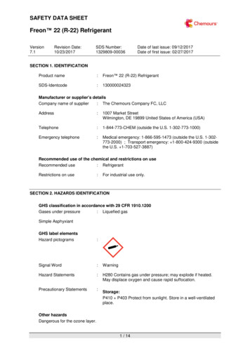
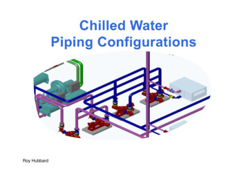
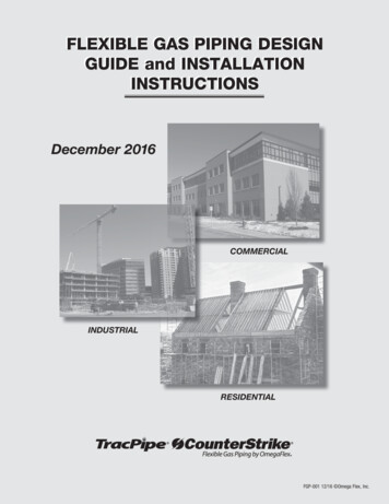
Suva refrigerantsRefrigerant PipingEquivalent Lengths of Nonferrous Valves and FittingsEquivalent Length is expressed in Feet of PipeLine SizeODGlobe /SolenoidValveAngle /CheckValve90 º SRElbow1/2951.40.95/81261.53/41477/8151 1/890 º LRElbow45 ºElbowEnlarging Coupling1/23/4Reducing Coupling1/23/4Tee Line 71.80.91.54.54.73.01.02.31.81.01 3/828153.62.41.21.86.05.83.61.22.92.21.21 5/835174.22.81.42.07.08.04.81.64.03.01.62 1/845225.93.91.83.010.0106.12.05.03.82.02 5/851266.94.62.23.512.0138.02.66.54.92.63 1/865347.75.52.74.515.0159.23.07.76.03.03 5/880409.86.53.05.017.017113.89.06.83.81/4dMuller Brass Co. DataNote: General accepted industry practice for determining the equivalent lengths for both P traps andU Bends is to add two 90 LR elbows of the specific OD tubing size for each component used.1/4DDdCarrier Engineering Manual number 3Enter table for losses at smallest diameter “d”Section 1 page . 9
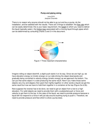
Suva Refrigerant PipingrefrigerantsCopper Tubing SpecificationsNominal (OD)DiameterType3/8DiameterOD InID InFlow Areasq. In.WeightLb/Lin 0.7850.4360.4840.6410.4551 1/8KL1.1251.1250.9951.0250.7780.8250.8390.6551 3/8KL1.3751.3751.2451.2651.221.261.0400.8841 5/8KL1.6251.6251.4811.5051.721.781.361.142 1/8KL2.1252.1251.9591.9853.013.102.061.752 5/8KL2.6252.6252.4352.4654.664.772.932.481967 ASHRAE Guide and Data Book3 1/8KL3.1253.1252.9072.9456.646.814.003.33{ Maximum allowable hanger distanceas per CSA B52 code3 5/8KL3.6253.6253.3853.4259.009.215.124.294 1/8KL4.1254.1253.5573.90511.712.06.515.38Maximum Spacing Between PipeSupports for Copper TubingNominal (OD)DiameterMax. Spanin Ft.5/87/81 1/81 3/81 5/82 1/82 5/83 1/83 5/84 1/8567891011121314{Based on ASTM B-88 standardSection 1 page . 10
SuvaWeight of Refrigerant in Copper Tubing refrigerantsPounds per 100 feet of Type K & L Tubing( Weight at 77ºF / 25ºC )Flow AreaTube O.D. (2) sq. in1/25/83/47/81 1/81 3/81 5/82 1/82 5/83 1/83 5/84 1/8KLKLKLKLKLKLKLKLKLKLKLKLCu ft /100ftR-1281.84 2.32L (1) VR-134aR-401AR-402A R-404A 16V75.28L2.02V74.52L1.81V71.86L4.32 65.45 4.00VL (3) 6115.40.960.63 11.40.3113.30.3812.10.4511.70.3711.70.67 487.43.2481.95.09171.34.86 156.05.78 151.04.79159.08.71 157.64.23 156.03.79 150.49.04137.08.37 148.25.48 138.88.62175.94.99 160.25.93 155.15.93163.28.94 161.84.34 160.13.89 154.49.28140.78.60 152.15.63 142.58.85264.77.50 241.08.93 233.47.41 245.6 13.45 243.56.53 241.05.85 232.413.97211.7 12.94229.08.47 214.413.327.59 251.7 13.79 249.56.69 247.06.00 238.114.32216.9 13.26234.68.68 219.813.659.31 343.58.34 331.219.90 301.7 18.43 326.3 12.10 305.718.99271.27.69 247.09.15 239.1377.210.70 343.512.72 332.610.55350.1 19.17347.0387.210.98 352.613.06 341.413.06359.3 19.68356.19.56 352.68.56 340.020.43 309.6 18.92 345.0 12.40 313.819.49511.414.50 465.717.25 450.914.31 474.6 25.99 470.412.62 465.711.31 449.126.99 409.0 25.00 442.416.37 414.425.7526.36523.614.84 476.817.66 461.714.65 485.9 26.62 481.612.92 476.811.58 459.827.64 418.7 25.59 453.016.76 424.3664.018.82 604.722.39 585.518.58616.3 33.75 610.816.39 604.714.68 583.135.10 531.1 32.46 547.521.26 538.133.43680.719.30 619.922.95 600.219.05631.7 34.60 626.116.80 619.815.05 597.735.93 544.3 33.27 588.821.79 551.634.27NOTES: (1). L . saturated liquid & density, V . saturated vapour & density, (2). Copper Tubing as per ASTM – B88, (3). for R-507 use R-404A valuesSection 1 page . 11
SuvaRefrigerant Receivers refrigerants( R-22 capacities at 90º F and 90% full. )Density of R-22 at 90º F is 72.71 lbs per cubic footVertical ReceiversHorizontal Receivers( R-22 capacity in lbs. )( R-22 capacity in lbs. )Dia. length lbs.Dia. length lbs.Dia.3.5 x 7.5 23.5 x 10 35x 28 189 3/4 x 22 5166x 30 28x 36 3410 3/4 x10 3/4 x10 3/4 x10 3/4 x10 3/4 x3648607296 10514217921629012 3/4 x12 3/4 x12 3/4 x12 3/4 x48607296 1962482994044x 10 455x 10x 20 6 136 5/8 x 38 43lengthlbs.7 5/8 x 28 416666xxxx12182430 101622288 5/88 5/88 5/88 5/88 5/8Note: Dia. and Length are in inchesxxxxx2836424860 53 69 81 93 117Dia. length lbs.1414x 72 363x 96 489161616x 60 388x 72 470x 96 63318x 72 597202020x 72 736x 84 866x 96 996Note: Dia. and Length are in inchesFor alternate refrigerant storage capacities in pounds for R-22 rated receiversmultiply the rated capacity by the following conversion factors.Example: A receiver that measures 12 3/4" x 72" has a R-22 rated capacity of 299 lbs.What is its revised capacity if this receiver is used with R-407C ?299 lbs x 0.9473 283 lbs.R-22 .R-123 .R-124 .R-134a .86820.94730.88531.0278R-410A . 0.8794R-507 . 0.8674Notes: Receivers capacities source . Standard Refrigeration Company.All dimensions are expressed in inches and all weights are expressed in pounds.Densities sourced from E.I. DuPont Thermodynamic Tables,R-507 . AlliedSignal Inc., computer program,R-408A and R-409A . Elf Atochem, computer program.Section 1 page . 12
SuvaTemperature / Pressure Chart CompleteRange of Temperature ApplicationsHigh, Medium and Low Temperature ApplicationsºFR-12R-22R-502R-134aR-404AR-407C refrigerantsVery Low Temperature 59-18-15-12- 9- 7434855626989991091211326673819099- 4- 5282302324347372445479510543577Bubble / 101- 98- 96- 93- 909”5”1”251471013036913- 87- 84- 82- 79- 76-100-95-90-85-8071114182317222632381721263238- 73- 71- 68- 66- 2606877- 59- 57- 54- 51- 9285951071191328798110122135- 46- 43- 40- 37- 136149146160176193211150165181198217- 32- 29- 26- 23- 21Bubble / DewNote: Pressure / ºC temperature values are rounded off to the nearest whole number, and the values are expressed in PSIG or inches Hg.Section 1 page . 13
Suva refrigerantsRefrigerant Line Identificati
Line Size OD Equivalent Lengths of Nonferrous Valves and Fittings Equivalent Length is expressed in Feet of Pipe Muller Brass Co. Data Suva refrigerants Section 1 page . 9 Note: General accepted industry practice for determining the equivalent lengths for both P traps and U Bends is to add two 90 LR elbows of the specific OD tubing size for each component used. Enlarging Coupling .