Transcription
North Cruise Berth ProjectsPortMiamiAAPA 2017 Facilities Engineering SeminarOct 24 – 26, 2017Carlos J. Arboleda, PEVice President – Project DirectorIntermodal Ports1
PortMiami “The Cruise Capital of the World” Contributes more than 41 billion annually toMiami-Dade County Miami’s second largest economic engine Generates approximately 324,000 direct andindirect jobs Close to 20 cruise lines berthing 45 ships,PortMiami moved close to 5 million cruisepassengers during 20162
PortMiami2016 Statistics3
PortMiamiNorth Cruise Berths 1 - 64
North Cruise Berths Projects5
PortMiamiAtkins has been assisting PortMiami on severalkey assignments in support of their cruise berthsover the past 10 years.1. PortMiami North Bulkhead Realignment Program2. NCB 1-6 Scour Bowl Restoration3. NCB 1-6 Cruise Bulkhead Cathodic Protection4. NCB 1-6 Seafloor Stabilization Pilot Program5. Marine Improvement to Berth 7, Cruise Terminal A6
North Bulkhead RealignmentProgram7
PortMiami North BulkheadRealignment Program2035 Port Master Plan recommended the development ofnew cruise berths to accommodate future demand.The fifteen year mid-term planning range for new cruiseberths was adopted into the Miami-Dade CountyComprehensive Development Master Plan (CDMP) onOctober 2, 2013 by the Miami-Dade County Board of CountyCommissioners. Currently the Port has six (6) north berths in operation Two (2) additional berths were considered (Berth 7 and Berth 8)8
PortMiami North BulkheadRealignment Program9
PortMiami North BulkheadRealignment Program10
PortMiami North BulkheadRealignment ProgramThe Port entered into an MOU with a terminal operatorto construct new berth 7 along the north side of thePort.Royal Caribbean Cruise Lines (RCL) beganconstruction of this new berth on February 27, 2017.Procured as a DFBOM-T, overall cost of the newterminal is approximately 216M.Second P3 initiative that PortMiami has done.11
PortMiami North BulkheadRealignment Program12
NCB 1-6 Scour Bowl Restoration13
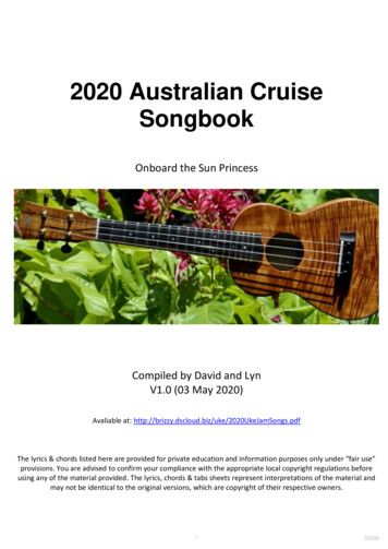
NCB 1-6 Scour Bowl RestorationThe objective of the scour bowl restoration is to prevent theexisting scour bowls from undermining the integrity of theembedment of the existing bulkhead wall. The proposedsheet pile toe wall combined with a concrete fill betweenthe existing wall and proposed wall will offer passiveresistance and stabilize the wall preventing sheet pileembedment failure. The target elevation to fill the scourbowls is at EL. (-) 37.0 NGVD,14
NCB 1-6 Scour Bowl RestorationBenefitsprovides for adequate embedment against scour.reduces lateral stress on the sea bottomreduces the negative and positive bending moment stressesChallengescutting, shaping and removing the sea bottom prior to installing sheet pilinginstalling/driving new toe wall sheet piling into the dense limestone sea bottomInstalling the toe wall in close proximity to the existing bulkheadcutting the toe wall underwater to final gradeplacing concrete underwater between the toe wall and existing sheet pilingenvironmental permitting requiredConstruction Issuestoe wall can be installed from landsidetoe wall can be constructed in sectionsinstallation crews can be working at different locationsinstallation equipment can be moved off the apron in cruise dayscruise ship berthing schedules can be accommodated15
NCB 1-6 Scour Bowl RestorationA multi-beam bathymetric survey was done by Morgan &Eklund in 2015 and updated in 2016. This information wasused by Atkins to confirm the presence (or lack thereof) ofpropeller washouts, scour bowls and other sea bottomanomalies that may have impact on the existing bulkheads.ScourBowlNo.CruiseTerminalBay No.Station3G264D28 to 3056789GDGDD333639535731 7534 00to36 0040 4543 1047 4064 1569 00SheetPile 33533Other Scour bowls along the North Bulkhead16
NCB 1-6 Scour Bowl Restoration17
NCB 1-6 Scour Bowl RestorationProposed installation of a newsheet pile toe wall at 5 feetwaterward of existing bulkhead.Concrete fill to be placed betweennew sheet pile toe wall and existingbulkhead wallRe-establishment of embedment atexisting bulkhead wall.18
NCB 1-6 Bulkhead CathodicProtection19
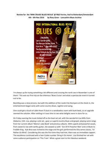
NCB 1-6 Bulkhead CathodicProtectionThe objective of the Cathodic Protection program is todevelop a plan for the installation of a ten (10) year(minimum) cathodic protection system for the existing steelsheet pile bulkhead along North Cruise Berths 1 through 6.Atkins and their subconsultant, Vector Corrosion Services,evaluated the use of corrosion management (cathodicprotection) to reduce the rate of corrosion of the steel sheetpilings (below water) and thereby preserve the remainingstructural integrity which would gain additional service life.Corrosion management in the form of cathodic protection isa proven cost effective method and may be applied to steelsheet pile bulkheads of the age installed along the Project20
NCB 1-6 Bulkhead CathodicProtectionData sets were utilized forthe corrosion rate analysisEach data set containedmeasurements at the top,mid-height and bottom ofwall.Corrosion rate selected foranode design was 3.5 mpy.21
NCB 1-6 Bulkhead CathodicProtection22
NCB 1-6 Seafloor StabilizationProgram23
NCB 1-6 Seafloor StabilizationProgramThe purpose of the seafloor stabilization program is toimprove the characteristics of the low quality rock strata atthe base of the bulkheads. The stabilization programunder evaluation is a pilot program that would addressabout 500 feet of the total 7,000-plus linear feet ofbulkhead serving Berths 1 through 6.The seafloor at the toe of the sheet pile typically consists ofpoor quality limestone. Stabilization of the seafloor isplanned to strengthen the limestone, increase resistanceagainst a toe failure of the sheet pile wall, and help protectagainst scour adjacent to the sheet piles.24
NCB 1-6 Seafloor StabilizationProgramBenefitsreduces sheet pile embedment requirementsstrengthens the sea‐bottom against scourChallengesdrilling grout tubes underwaterfilling the tubes with groutcontrolling the grout disbursementConstruction Issuesgrout tubes can be installed from landside but divers are required.grouting can be deployed in sectionsinstallation crews can be working at different locationsinstallation equipment can be moved off the apron in cruise dayscruise ship berthing schedules can be accommodatedenvironmental permitting required25
NCB 1-6 Seafloor StabilizationProgramThe suggested location for the pilot program implementation iswithin the limits of Berth 5. The area from station 58 80 to station63 80 is located within the limits of the original 1960’s bulkheadwall and does not overlap with any of the scour bowl restorationareas .26
NCB 1-6 Seafloor StabilizationProgramGrout tubes would beplaced at 3-foot intervalsto facilitate stabilization ofthe seafloor adjacent tothe sheet piles27
Marine Improvements North CruiseBerth 7 – Cruise Terminal A28
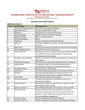
Marine Improvements North CruiseBerth 7 – Cruise Terminal AIn a public-private partnership (P3) agreement withMiami-Dade County, Miami Cruise Terminal A, LLC, willbe constructing and operating a new signature cruiseterminal (Cruise Terminal A), provisioning building,parking garage, intermodal areas and a new cruise shipberth all to be located on the northeast quadrant ofPortMiami. The new cruise berth needs toaccommodate a 400 meter LOA (1,312 feet) StretchOasis Class RCCL cruise ship with extended mooringline zones, both forward and aft of the ship. Whencompleted, new Cruise Berth 7 will have an overalllength of about 443 meters (1,454 feet)29
Marine Improvements North CruiseBerth 7 – Cruise Terminal AImage retrieve from Google Earth30
Marine Improvements North CruiseBerth 7 – Cruise Terminal AAtkins was retained as the Engineer of Record and is providing marineengineering design for the bulkheads including walers, tie-rods andanchor walls, stormwater management plans, apron pavement anddrainage.The design vessel for this project is the RCL Oasis of the Seas andStretch-Oasis Class vessels with the following characteristics:Class: Oasis of the SeasLength Overall (LOA): 1,187 feetDistance between perpendiculars: 1,082.5 feetBeam at waterline: 154.2 feetDraft (fully laden) 30.5 feetSide Windage Area 162,158 square feetDisplacement 104,350 long tonsClass: Stretch-Oasis Class Cruise ShipLength Overall (LOA): 1,312 feetDistance between perpendiculars: 1,148 feetBeam at waterline: 154.2 feetDraft (fully laden) 30.5 feetSide Windage Area 183,837 square feetDisplacement 119,386 long tons31
Marine Improvements North CruiseBerth 7 – Cruise Terminal AStructural MembersMember sizes considered for thebulkhead wall, anchor wall, and tierods are as follows: Bulkhead wall: PAZ42/AZ26-700Combi-Wall, 5/8-inch pipethickness, ASTM A572, Grade 50 Anchor wall: SKZ 31, Cold rolledASTM A572, Grade 50 Tie rods: 2.5-inch diameter, ASTMA615 Grade 75 Waler at anchor wall: DoubleC15x40, ASTM A572, Grade 50,back-to backInsert image caption(s) and copyright text32
Marine Improvements North CruiseBerth 7 – Cruise Terminal AConcrete CapThe current bulkhead designincludes a concrete cap withintegrated removable curbrailing. The top of thecap is sloped to drain watertowards the apron and towardsstormwater conveyancesystem. The high side of the topof the cap is at EL ( ) 11.00,sloping back to EL ( ) 10.75 onthe landward side of the cap.33
Combiwall Installation34
Marine Improvements North CruiseBerth 7 – Cruise Terminal AAerial Photo provided by Moss / Smith Aerial Photos35
Thank youIf you’d like to find out more visit:www.atkinsglobal.com Atkins Limited except where stated otherwise.The Atkins logo, ‘Carbon Critical Design’ and the strapline‘Plan Design Enable’ are trademarks of Atkins Limited.Atkins North America, Inc.800 Waterford Way, Suite 700Miami, FL 33126Tel: (305) 592-727536
Sheet Pile Tip (EL., NGVD) Scour Depth (EL., NGVD) Target (EL., NGVD) Approx. Length (Feet) Approx. Width (Feet) Approx. Depth (Feet) 3 G 26 31 75 -50 -44 -37 40 20 6 4 D 28 to 30 34 00 to 36 00-45 -44.5 -37 200 20 6 5 G 33 40 45 -45 -41 -37 20 15 3 6 D 36 43 10 -45 -41 -37 15 10 3 7 G 39 47 40 -45 -42 -37 40 10 5 8 D 53 64 15 -45 -41 -37 30 10 3