Transcription
VWEA16 Rogers Hydraulic Considerations in Pumping System DesignHydraulic Considerations inPumping System DesignVWEA Wastewater Operations Education ConferenceRoanoke VirginiaJuly 14, 2016
Agenda Basics of Hydraulics and Pump Operation Pumping System Design Process Types of Pumps System Curve Development Pump Station Layout Pump Selection Considerations Hydraulic Concerns Case StudiesVWEA16 Rogers Hydraulic Considerations in Pumping System Design Summary Questions
3VWEA16 Rogers Hydraulic Considerations in Pumping System DesignAbbreviations and Acronyms BEP – best efficiency pointBHP – brake horsepowerfps or ft/sec – feet per second (velocity)FM – force maingpm – gallons per minute (flow)H – Head (feet)HP – horsepowern – rotational speedNPSHA – net positive suction head availableNPSHR – net positive suction head requiredpsi – pounds per square inch (pressure)Q – Flow Rate (gpm, mgd, cfs )rpm – revolutions per minuteTDH – total dynamic head
Basics of Pump Operation A pump lifts fluid from one elevation to another Work is needed to lift fluid Work is independent of type Human PowerAnimal PowerWind PowerSteam PowerElectrical PowerVWEA16 Rogers Hydraulic Considerations in Pumping System Design Pump can lift continuously or in increments Take-away: Higher lift requires more work Higher flow requires more work Faster work requires more power
VWEA16 Rogers Hydraulic Considerations in Pumping System Design Pumps deliver fluid against pressure Pressure Force / Area (psi) Head (feet) is commonly used to express pump operatingpressure A 2.31 foot high column of water exerts a pressure equal to 1 psi i.e. Car tires 35 psi 81 feet of head
Closed Conduit Flow (Q) Volume of fluid passing per time (gpm, mgd, cfs ) Q (cfs) Area (ft2) x Velocity (fps) For a given flow, the smaller the conduit the largerthe velocity.VWEA16 Rogers Hydraulic Considerations in Pumping System Design Higher velocity translates into increased frictionalheadloss
TDH is the total amount of head a pump mustoperate against to deliver wastewater to a desiredlocation TDH Static Head Head Loss (HL)VWEA16 Rogers Hydraulic Considerations in Pumping System Design Static Head – exists when pump is on or off Head Loss – exists only when fluid is pumped
For free surfaces: Static Head Discharge Tank WSEL – Suction Tank WSEL Static Discharge Head Discharge Tank WSEL – Pump CLVWEA16 Rogers Hydraulic Considerations in Pumping System Design Static Suction Head Suction Tank WSEL – Pump CLSuction Lift – Negative Suction HeadFlooded Suction – Positive Suction Head
Energy dissipated due to friction andturbulence during pump operation Major Losses (Friction Losses) Due to friction between pumped water and inner surfaceof piping Hf 3.02 L D-1.167 (V/Ch)1.85 (Hazen-Williams Formula)where:VWEA16 Rogers Hydraulic Considerations in Pumping System Design L is length of pipe (feet)D is diameter of pipe (square feet)V is mean velocity (fps)Ch is Hazen-Williams friction coefficient (new up to 140 and old aslow as 80) Minor Losses Due to turbulence at bends, fittings, valves, etc. Hf K (V2/2G) (Headloss factor times velocity head)
NPSHA Atmos. Head Static Suction Head – Suction HL Standard atmospheric pressure 14.7 psi (34 ft. head) Net Positive Suction Head Required (NPSHR) Furnished by pump manufacturer – pump specific Increases with pump flowVWEA16 Rogers Hydraulic Considerations in Pumping System Design NPSHA NPSHR Cavitation Typically occurs in systems with static lift Could occur in flooded suction scenario with extremely longlengths of suction piping Insufficient submergence can lead to vortexing
Work A force does work when it actson a body over a distance Units of foot pound (ft-lb) Wastewater pumps do work tomove the wastewater PowerVWEA16 Rogers Hydraulic Considerations in Pumping System Design Rate of work done (ft-lb/s) Wastewater pumps most oftendo work by using electricmotors Motors are commonly rated byhorsepower (hp) 1 unit of hp is equal to 550 ftlbs/s
12VWEA16 Rogers Hydraulic Considerations in Pumping System DesignThe Pumping System Design Process Collect informationDetermine type of pump to be usedDevelop station layoutDevelop system curvesSelect pumps that match the system curvesWrite your specificationCoordinateFinalize the design
13VWEA16 Rogers Hydraulic Considerations in Pumping System DesignCollect Information What – type of fluid is to be pumped? Fluid properties: density, viscosity, solidscontent, temperature From where to where? System characteristics: friction and minorlosses, suction lift, static head, other pumpsoperating simultaneously How much – what are design flowrates?
14Determine Type of Pump Flow and head requirements Type of fluid, solids content Site conditionsVWEA16 Rogers Hydraulic Considerations in Pumping System Design Footprint and headroom constraints Subgrade conditions Elevation constraints Suction and discharge inverts Suction head availableMore than one type may work - what’s best for the specificapplication and owner preference?Fairbanks-Morse
15Types of PumpsPump TypesCentrifugalSingle suctionDouble suctionRadial FlowMixed FlowAxial FlowKineticPeripheral/RegenerativeSpecialVWEA16 Rogers Hydraulic Considerations in Pumping System f-primingOpen impellerSemi-open impellerClosed impellerJetGas liftHydraulic DiaphragmVaneGearLobeScrewPistonHoseHydraulic Institute
Types of Pumps Kinetic (Rotodynamic) Pumps Energy is imparted to the fluid by a rotating impeller which increasesthe flow velocity and converts to a pressure increase upon exit. Can be safely operated under closed valve conditions (for shortperiods of time). Three Types: Radial-flow pumps (Centrifugal Pump) - higher pressures and lower flow rates thanaxial-flow pumps. Axial-flow pumps - lower pressures and higher flow rates than radial-flow pumps. Mixed-flow pumps – A compromise between radial and axial-flow pumps - operate atVWEA16 Rogers Hydraulic Considerations in Pumping System Designhigher pressures than axial-flow pumps while delivering higher discharges than radialflow pumps. Positive Displacement (PD) Pumps PD pumps physically displace fluid Closing a valve downstream can lead to continual pressure build up andfailure of pipeline
Positive Displacement PumpsLobe PumpHose PumpVWEA16 Rogers Hydraulic Considerations in Pumping System DesignHP Reciprocating Triplex PumpProgressing Cavity Pump
Progressing Cavity PumpsVWEA16 Rogers Hydraulic Considerations in Pumping System Design Flowrate fixed to speed Capable of pumping highly viscous stream Commonly used in sludge and slurry pumpingapplications Operates at high pressures Must avoid running pump dry Provide safety features on discharge
Centrifugal PumpVWEA16 Rogers Hydraulic Considerations in Pumping System DesignA centrifugal pump lifts fluid from one elevation to another by continuouslyadding kinetic energy (accelerating the fluid) using a rotating impeller
20Common Types of Centrifugal Pumps forWater and Wastewater Horizontal Split Case Pumps Vertical Turbine PumpsVWEA16 Rogers Hydraulic Considerations in Pumping System Design End Suction Pumps Closed impeller Non-Clog pumps Submersible non-clog pumps
Horizontal Split CaseApplications Water treatment: Raw Water High service pumping Transfer pumping Wastewater treatment:Characteristics Wide flow range Heads to 500 ft. for single stage,higher for two-stage High efficiency (85-95%) Ease of maintenance Flat curveVWEA16 Rogers Hydraulic Considerations in Pumping System Design Reuse filter feed Reuse distribution Treated effluent pumpsConfigurations Horizontal motorVertical motorSingle or two stageDual diesel / electric driveHorizontalVertical
22Vertical TurbineApplications Water treatment: Raw water pumps Groundwater pumps(submersible) Membrane feed pump Filter backwash pump High service pumps Transfer pumpsVWEA16 Rogers Hydraulic Considerations in Pumping System Design Wastewater treatment: Reuse filter feedReuse distribution pumpsTreated effluent pumpsVTSH (vertical turbine solidshandling)Characteristics Wide flow range Wide head range – addstages for higher head Steep curve Very compact footprint Prone to vibration Difficult to serviceConfigurations Can-type Wetwell-mounted Submersible
End SuctionApplications Water treatment: Booster PumpingFilter BackwashMembrane FeedChemical FeedRaw water Wastewater treatment(non-clog impellers):VWEA16 Rogers Hydraulic Considerations in Pumping System Design Sewage lift stations Raw sewage pumpsCharacteristics Low to Medium flow High head - add stages Curve shape variesConfigurations Vertical - save space or to mountmotor above flood elevation Horizontal - provides goodaccess and saves head room Close-coupled (singlepump/motor shaft) Direct coupled (motor shaftconnected to the pump shaft bya shaft coupling) V-belt drive Extended shaft Submersible
24End Suction Pumps – WastewaterVWEA16 Rogers Hydraulic Considerations in Pumping System Design Heads to 250 ft. for a single stage Best efficiencies 70-75% Impeller options:Channel ImpellerVortex ImpellerSemi-Open Impeller(recessed impeller)(enclosed, 1-3 vanes)Sewage lift stationtypical applicationGrit and sludge pumpingtypical applicationsSolids handling performance improvesHydraulic efficiency increases
25Pump Type Selection Example – Griffith RWPSSelected horizontal split-case pumps – why? Had available land area and suction head Rock subgrade Suitable curve shapeVWEA16 Rogers Hydraulic Considerations in Pumping System Design Owner preference Ease of maintenance
Centrifugal Pump Summary Larger impellers - Greater flow and head Greater Speed – Greater flow and head Larger, slower impellers are more efficient but cost more Pumps in parallel - more flow at same headVWEA16 Rogers Hydraulic Considerations in Pumping System Design Pumps in series - higher head at same flow Generally, power increases as flow increases to run out Best efficiency point (BEP) is at max of efficiency curve
Centrifugal Pumps - Points to Watch Rotational speeds 1,800 rpm Non-clog in particular Flooded suction - no priming needed Curve shall continually rise to shut off Steeper pump curves are best for VFDsVWEA16 Rogers Hydraulic Considerations in Pumping System Design Duty point to be 75% Qmax, close to BEP Aim for efficiencies 75% single stage Size motor HP for “run out” or maximum power NOT duty point
28Station Layout - Where to Start? Resources Hydraulic Institute (HI) Standards, other references Consider constraints – site, budget, etc. Collect/develop information needed to create systemcurvesVWEA16 Rogers Hydraulic Considerations in Pumping System Design Elevations of suction, pump room floor, high points, dischargeFor retrofits, survey/measure existing elevations, testexisting pumps for flow and pressure Develop piping system layout, list of minor losses
29Station Layout Considerations Provide sufficient work space between pumps Use largest pump and motor dimensions (now or future) Allow for expansionVWEA16 Rogers Hydraulic Considerations in Pumping System Design Think through process of installing/removing pumps and valves Size crane and openings for heaviest / largest single item in the station Ensure crane can reach everything it needs to lift Consider need for portable hoists or truck access, etc. when selectingpump spacing, sizing hallways Involve operations and maintenance staff early
30Layout - Hydraulic Institute Standards American National Design Standards for Pump Intake and CentrifugalPumps Wetwells - different designs for clear and solids-bearing liquids Provide steady, uniform flow with minimal flow disturbances Keep solids entrained Piped intakes – recommended piping configurations, velocity limitsVWEA16 Rogers Hydraulic Considerations in Pumping System Design Canned vertical turbine pumps – geometry and velocity specifications No flow disturbing fittings within 5 pipe diameters of suction Long-radius bends and full-port valves are not considered flow disturbing
31Points to Watch – Suction and DischargePiping Suction pipe velocities 6 ft/s Delivery pipe velocities 8 ft/s Avoid applying forces (especially unbalancedones) to pumps via piping and valves Provide pipe supports No horizontal bends near pumpsVWEA16 Rogers Hydraulic Considerations in Pumping System Design Use long radius elbows for vertical suction bends Avoid creating high points On suction, use eccentric reducers with flat side up Continuously rising discharge pipe alignment Provide isolation valves Include restrained flexible couplings Pipe/flanges rated for worst case pressures, including surge / test pressures
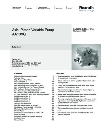
32TOTAL HEAD, HTVWEA16 Rogers Hydraulic Considerations in Pumping System DesignDeveloping System CurveThere will be severalsystem curves for a givenapplicationUse real elevations on yaxis, not TDH of pumpFriction Head hlf hlmSystem CurveFriction HeadStatic HeadFLOW RATE, QStatic Head zdisch - zsuctionTotalHead
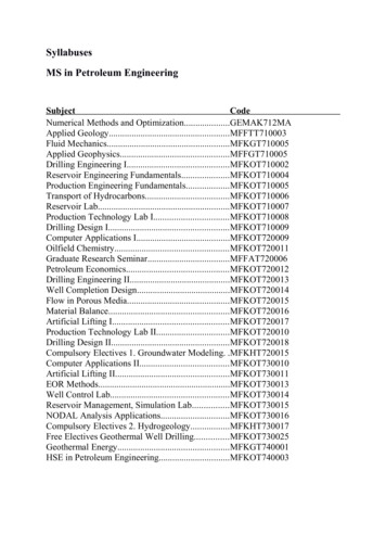
33System Curve WorksheetExample Pump StationForce Main Conditions:Flow Scenario:Number ofPumps Total StaticHead Hazen-Williams C:ADF(mgd)0.875Peak (mgd)Minor Losses in Pipe Reach -- Pump 1A. Suction-10" inside PSMinor loss typeK-valueslightly rounded entrance0.23gate valve0.1990 elbow0.310x5" reducer0.2590 elbow0.31202.51102.42Flow Unit Fric Form Coefficients for Flow Units MGD19087801250.6A. SubtotalDEFINE PIPE SYSTEM11111Sum KKfKm1.27 2.231E-07 3.294E-075.54 7.214E-07 3.508E-062.24 0.000E 00 0.000E 006.85 1.162E-05 4.625E-072.2 1.034E-05 1.485E-07400350SYSTEMCURVETotalFlowgpmTDHft0 296.42250 297.03500 298.73750 301.451000 305.171250 309.871500 315.531750 322.132000 .7632.39Kf*Q 1.85 Km*Q 0Head (ft)VWEA16 Rogers Hydraulic Considerations in Pumping System DesignPipeDia.LengthReach (in.)(feet)H&W C Frac 2502000500100015002000Flow (gpm)System Head (single FM)25003000
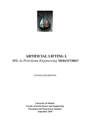
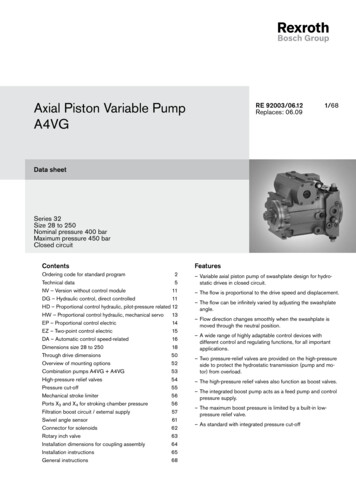
34The Pump Curve3 Best Efficiency Point (BEP)TOTAL HEAD, HTVWEA16 Rogers Hydraulic Considerations in Pumping System DesignShut-Off Head Point2Efficiency CurveOperating PointPump Curve1System Curve4Run-Out PointBHP CurveNPSHR CurveFLOW RATE, Q
System Curve Envelope and Pump CurvesPump CurvesTOTAL HEAD, HTVWEA16 Rogers Hydraulic Considerations in Pumping System DesignSystem Curve 2System Curve 1This pumpis notpumpingOne duty point does NOT define a pump curve.A flat pump curve is very sensitive to system curve changes.FLOW RATE, Q
System Curve ConsiderationsTOTAL HEAD, HTVWEA16 Rogers Hydraulic Considerations in Pumping System DesignPump CurvesFuture System CurveExisting System CurveSystem losses can increase significantly over time.FLOW RATE, Q
VWEA16 Rogers Hydraulic Considerations in Pumping System Design37Pump Curve
“Droopy” Pump CurvesTwo potential OperatingPoints – unstableTOTAL HEAD, HTVWEA16 Rogers Hydraulic Considerations in Pumping System DesignNormal pump curve compared to “droopy” curve.Pump curves shall continuously rise to shut off.System CurveFLOW RATE, Q
Curves – Pumps in ParallelTOTAL HEAD, HTVWEA16 Rogers Hydraulic Considerations in Pumping System DesignPump Curves for two equalcapacity pumpsPump 1System CurveFLOW RATE, QPumps 1 and 2
Curves – Pumps in SeriesPump Curve for two equalpump impellers in seriesSecond stage or pumpTOTAL HEAD, HTVWEA16 Rogers Hydraulic Considerations in Pumping System DesignSystem CurveFirst stage or pumpFLOW RATE, Q
Curves – Pumps with Variable FrequencyDrives (VFD)Pump Curves at different speedsTOTAL HEAD, HTVWEA16 Rogers Hydraulic Considerations in Pumping System DesignSystem Curve 1System Curve 2FLOW RATE, Q
42Affinity Laws - Variable SpeedQ2 Q1 * N2N1H2 H1 * N2N12VWEA16 Rogers Hydraulic Considerations in Pumping System DesignManufacturer PumpCurvesGoulds 3316 6x8-171786Curve Speed17.00Max Impeller14.25Curve 75737066625649403018-95.01697% ed Pump Curves% Speed 85.0 % 536637638439239940541041341742042480.61440% SpeedRPM75.01340% 85293299305311315319322325327330
TOTAL HEAD, HTVWEA16 Rogers Hydraulic Considerations in Pumping System DesignPreferred Operating Range70% of BEPBEPPump CurvePORFLOW RATE, Q1120% of BEP
TOTAL HEAD, HTVWEA16 Rogers Hydraulic Considerations in Pumping System DesignAllowable Operating Range50% of BEPBEPPump CurveAORFLOW RATE, Q1125% of BEP
Operating Outside of POR/AORVWEA16 Rogers Hydraulic Considerations in Pumping System Design Several issues occur when operating outside theseranges: Recirculation Excessive Noise Excessive Vibration Cavitation Pump Damage
Results when liquid is subject to rapid changes ofpressure that cause the formation of cavities wherepressure is relatively low The formation and collapse of cavities or gas pocketscan cause mechanical damage to impellerVWEA16 Rogers Hydraulic Considerations in Pumping System Design Accompanied by loud noises Caused by insufficient NPSH
Net Positive Suction Head (NPSH) –Avoiding CavitationVWEA16 Rogers Hydraulic Considerations in Pumping System Design NPSHA – Total suction head available at the pump inletNPSHA hatm hss hvs - hl - hvapWhere: hatm atmospheric pressure head ( 34 ft) hss static suction head hvs suction velocity head (v2/2g) hl headloss (friction minor losses) in suction piping hvap vapor pressure head of liquid being pumped (table lookup based onpressure, temp – Ex. 1.18 ft. for water at 1 atm and 80 F) NPSHR – net positive suction head required, as published by manufacturer Defined by HI as the NPSH that causes the total head of the pump (or 1ststage of pump if multi-stage) to be reduced by 3% at a specific rate of flow NPSH Margin (NPSHA/ NPSHR) – 1.1 to 2.0 (ANSI/HI)
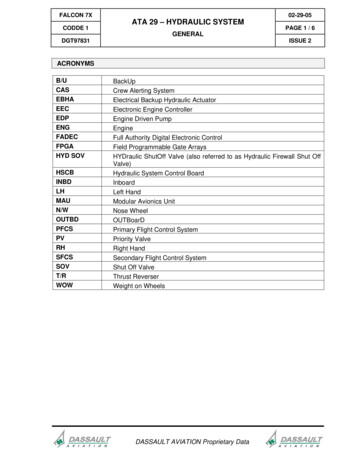
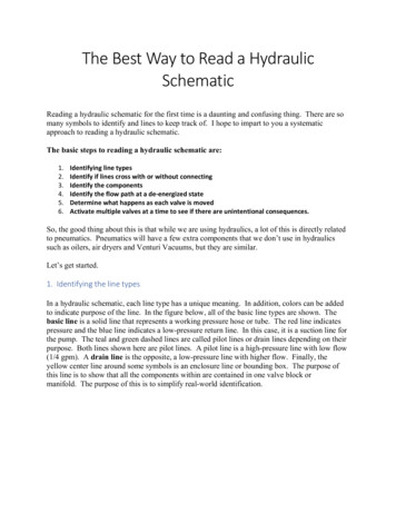
48Example of NPSHA/ NPSHRExample Pumping StationSingle Pump Operating50NPSH (ft. abs.)VWEA16 Rogers Hydraulic Considerations in Pumping System Design40NPSHA/ NPSHR 36 / 22 1.630201000100020003000Flow (gpm)NPSHANPSHR4000
49Correcting NPSH Problems Increase wetwell level or supply pressure Lower pump elevation Reduce headloss in suction pipingVWEA16 Rogers Hydraulic Considerations in Pumping System Design Check for blockages in pipeEnsure that valves are operating correctlyIncrease diameter of suction pipingUse long-radius bends Select (or run at) a lower speed pump Choose pump with larger suction diameter
Also known as hydraulic shock or surge An oscillation in pressure resulting from a rapid increaseor decrease in flow (stopping pump, closing valve) Causes serious mechanical damage and loud noisesVWEA16 Rogers Hydraulic Considerations in Pumping System Design Surge valves can help minimize water hammer
VWEA16 Rogers Hydraulic Considerations in Pumping System DesignWater HammerΔh
Case Study – Flow Equalization Basin Prestressed Concrete Ground Storage Tank Pumped Influent, Gravity DrainVWEA16 Rogers Hydraulic Considerations in Pumping System Design Varying Water Levels Pose Hydraulic Challenges40’ to 45’
Case Study – Flow Equalization Basin100.0090.00 Pumps off curve at full andreduced speed when WSE is low.80.0070.0060.00TDH (Feet)50.0040.00VWEA16 Rogers Hydraulic Considerations in Pumping System Design30.0020.0010.000.000102030Flow (MGD)405060
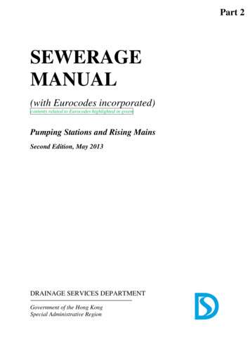
Case Study – Flow Equalization Basin100.0090.0080.0070.00TDH (Feet)60.0050.0040.00VWEA16 Rogers Hydraulic Considerations in Pumping System Design30.00 Addition of a standpipechanges effective WSE seenby pump20.0010.000.000102030Flow (MGD)405060
Case Study – DC Water Blue Plains FADFFIP System (10) 100 MGD Vertical Turbine Pumps Magnetic Drives limit to 90% turndown Insufficient Submergence Pumps, motors and mag drives at end of life Slamming of check valves Undersized air and vacuum valves Proposed System: (10) 70 MGD Constant Speed Pumps (2) 50 MGD Pumps (VFD’s)VWEA16 Rogers Hydraulic Considerations in Pumping System Design Premium Efficiency Motors New Medium Voltage Electrical Facility Increase in Forebay WSE Floating Datum Concept Refine Control Strategy
FIP System – Energy Savings Replacement Pumps, Motors and Controllers Proposed Control Strategy Trial by locking Mag Drives at 100% with FIP 11 and 12 as trim pumps Operational Changes: Discharge to FIC – WSE at 26’ Increase Forebay WSE – Floating Datum conceptVWEA16 Rogers Hydraulic Considerations in Pumping System Design Datum a function of influent flow and headloss Energy savings of approx. 160,000 / year
Case Study – DC Water Blue PlainsRWWPS2 (9) 100 MGD Split Case Centrifugal Pumps Rehabilitate for 20 year design life On site repairs Off site rehabilitation Allowance for unanticipated work Motor replacement Controller replacement Rehabilitate Discharge Siphons Design point correctionVWEA16 Rogers Hydraulic Considerations in Pumping System Design Energy Savings Refine Control Strategy
RWWPS 2 - Discharge Siphon Improvements Rehabilitation of pumps and operation ofthe wet well at a higher WSE alleviatesneed for vacuum priming system Restore siphon operations – 12” vent Discharge check valveVacuum breaking valveVWEA16 Rogers Hydraulic Considerations in Pumping System Design Corrects the pumps primary operating point Provides for energy savings 4’ high pointPCS data shows ADF of 165 MGDWire to water efficiency of 70%Energy cost 0.09/kWhApproximately 100,000 / year in consumption
59Summary – Pump and System Curves There will be several system curves – explore allboundaries – low and high flow / elevations, existingand future C-factors Use real elevations for system curves (not pump TDH) Avoid flat pump curves if VFDs to be used Use affinity laws to explore speed impactsVWEA16 Rogers Hydraulic Considerations in Pumping System Design Duty point to be 75% Qmax, close to BEP Aim for efficiencies 75% single stage
Summary - Centrifugal Pump Selection Single duty point is insufficient to specify pump Give secondary points for VFD reduced speed curves No droopy curves – unstable operation - “shallcontinuously rise to shut off”VWEA16 Rogers Hydraulic Considerations in Pumping System Design Size motors for Run Out / Maximum HP Make sure pump motors are inverter-rated if using VFDs Pump motors can be noisy and generate heat (VFDs too)
61Summary - Good Hydraulic Design Develop system curves early Get real data – measure, survey, test Follow HI Standards The best flow path is a smooth one Don’t forget NPSH – no cavitation!VWEA16 Rogers Hydraulic Considerations in Pumping System Design Consider surge pressure in design Consider the full range of possible operating conditions,now and future Provide flexibility and expandability Work with vendors and O&M staff Iterative process
Acknowledgements / Useful Web Sites Hydraulic Institute Standards – www.pumps.orgVWEA16 Rogers Hydraulic Considerations in Pumping System Design Books: Pumping Station Design – Sanks, Perry’sChemical Engineers’ Handbook, Cameron HydraulicData, etc. Other useful websites: www.pump-zone.com www.pumped101.com www.mcnallyinstitute.com www.pumpcalcs.com www.eere.energy.gov Hazen colleagues - Brian Porter, Bryan Lisk and EllenHall, among others
Questions?Tad Rogers, PE, CCCA, ENV-SPRichmond, VAVWEA16 Rogers Hydraulic Considerations in Pumping System Design(804) 605-8525grogers@hazenandsawyer.com
n Energy dissipated due to friction and turbulence during pump operation Major Losses (Friction Losses) Due to friction between pumped water and inner surface of piping H f 3.02 L D-1.167 (V/C h)1.85 (Hazen-Williams Formula) where: L is length of pipe (feet) D is diameter of pipe (square feet) V is mean veloci