Transcription
CHAPTER 6: DESIGN AND CONSTRUCTION OFSLUDGE TREATMENT FACILITIESPart A: EngineeringCHAPTER 6: DESIGN AND CONSTRUCTION OF SLUDGE TREATMENT FACILITIES6.1THE APPROACHIn STP, sludge means the following. Primary sludge – When raw sewage is settled in a primary clarifier, the suspended solidssettle down by gravity. These are drawn out from the conical floor of the clarifier. This is calledprimary sludge (PS). It will have mostly organic substances and also inorganic substances. If it isstored, the organic substances will undergo anaerobic reaction as in Figure 5.2. This will result inproduction of Methane and Hydrogen Sulphide gases. Secondary sludge – When the sewage is aerated in aeration tanks, biological microorganismsgrow and multiply. The aerated liquid is called the mixed liquor. It is settled in secondary clarifiersto separate the microorganisms by gravity. These are drawn out from the conical floor of theclarifier. This is called secondary sludge. Return sludge – A major portion of the secondary sludge is returned to the aeration tank forseeding the microorganisms. This is called return sludge (RS). Excess sludge – A small portion of secondary sludge is wasted. This is equal to secondary sludgeminus return sludge. This is called excess sludge (ES) on waste sludge (WS). Chemical sludge – When raw sewage or secondary treated sewage is subjected to chemicalprecipitation, the resulting sludge is called chemical sludge (CS).In treatment units such as MBR, there are two optional arrangements for separating thetreated sewage from the aerated mixed liquor.In one type, the filtration membranes are submerged into the mixed liquor and the treatedsewage is sucked out as the filtrate. In this case, there is no secondary sludge or return sludge.The mixed liquor itself is separately wasted as excess sludge.In another type of MBR, the membranes are outside the aeration tank and the mixed liquor isfiltered into treated sewage and secondary sludge.The primary and excess sludge are to be further treated to produce fully inert matter which will notdecay any further. Normally this is achieved by the treatment process in Figure 5.2. Here theorganisms themselves are food source for new organisms till almost all organisms are reduced.This process also produces methane and hydrogen sulphide gases. The hydrogen sulphide isremoved and the methane is sent to gas engines to generate electricity.Alternatively, it can also be achieved by the treatment process in Figure 5.1, but this will needaeration and hence electrical energy is to be spent.The typical sludge generation values are shown in Table 6-1 overleaf.The illustrative computation of sludge generation values from ASP is in Appendix A.6.1.6-1
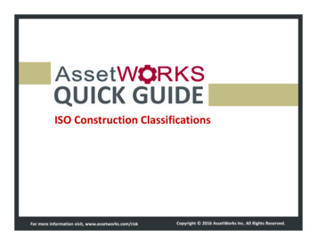
CHAPTER 6: DESIGN AND CONSTRUCTION OFSLUDGE TREATMENT FACILITIESPart A: EngineeringTable 6.1 Typical sludge generation valuesThe capacity of each sludge treatment unit is determined by considering the operating hours,sludge moisture content, retention time, etc., and is based on the solids balance of the entire sludgetreatment facility. The solids balance considers the reduction due to gasification, return load fromeach facility and the increase due to addition of chemicals, etc. This is important for sizing thesludge treatment units.In general, the primary and excess sludge will need a blending tank before further treatment so thatthe properties are made almost uniform when feeding the units. After this, if the thickened sludgeis put through anaerobic digestion as in Figure 5.2 for producing Methane, it is called anaerobicdigester. If it is oxidized as in Figure 5.1, it is called aerobic digester. In both cases, thedigested sludge will have to be dewatered. There are many types of equipments like centrifugeor filter press or natural solar drying beds for this purpose. The solids concentrations by differenttreatment processes are listed in Table 6.2.Table 6.2 Solids concentration by treatment processSource: Guideline and Manual for Planning and Design in Japan, JSWA, 2009An illustrative solids balance in two different types of sludge treatment processes is shown inFigure 6.1 overleaf. In this figure, a pertains to direct dewatering and incineration and b pertainsto the case of digestion, dewatering and incineration.Appendix A.6.2 illustrates the calculations further.6-2
CHAPTER 6: DESIGN AND CONSTRUCTION OFSLUDGE TREATMENT FACILITIESPart A: EngineeringFigure 6.1 Example of solids balance (Conventional Activated Sludge Process)In case of option a (dewatering and incineration) the solids balance occurs as follows. The solids load from the STP to the sludge treatment section is taken as 100. The solids load from the recirculation from the various units is taken as 22.1. Thus, the solids load entering the sludge treatment units is 122.1 The solids load escaping in the liquid portion from the blending tank is taken as 10 Thus, the solids load entering the sludge thickener becomes 112.1 The solids load escaping in the liquid portion from the thickener is taken as 11.2 The solids load leaving the thickener becomes 100.9. In the dewatering centrifuge, solids load from polyelectrolyte is 0.8 Thus solids load entering the dewatering centrifuge is 101.7 The solids load in the dewatered cake is 96.6 The solids load of 5.1 is in the filtrate and is recirculated The solids load of 96.6 in the dewatered cake is sent to fluidized bed and incinerator Here, the solids load of 67.6 goes into the formation of combustion gases The solids load of 5.8 escapes in the liquid portion of the fluidized bed The solids load of 23.2 remains in the final product as ash.Similarly, in the case of process b, the solids load in the final product becomes 22.7 instead of 23.2 inprocess a. Moreover, a digestion gas equivalent of 39.5 is gained, which in turn is a source of energy.6-3
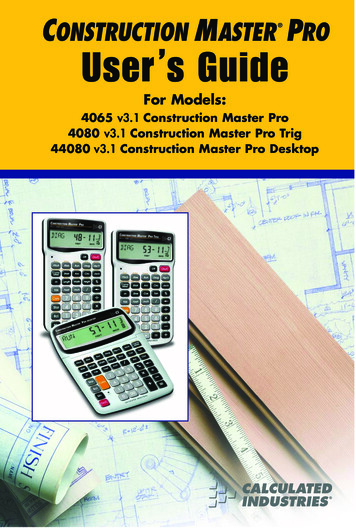
CHAPTER 6: DESIGN AND CONSTRUCTION OFSLUDGE TREATMENT FACILITIESPart A: EngineeringThus, anaerobic digestion has its importance. The solids recovery rate varies at each stage of sludgetreatment and is shown in Table 6.3.Table 6.3 Example of solids recovery rate in each treatment stageSource: Guideline and Manual for Planning and Design in Japan, JSWA, 20096.2HYDRAULICS OF SLUDGE PIPELINES6.2.1Sludge PipingSludge piping can be by gravity or by pumping. For example, when primary sludge is drawn fromclarifiers, it is sometimes by gravity and sometimes by direct suction using pumps. The friction lossin gravity pipelines and pumped pipelines are calculated as follows.6.2.1.1Friction losses in Gravity Sludge Pipelines1. Calculate friction loss using Manning’s formula as though it is flowing with water.2. This friction loss is multiplied by a friction compounding factor (F) as follows3. Estimate the solids content in the sludge (P).4. F for undigested sludge is 2.88 (0.176 P P) – (0.866 P)5. F for digested sludge is 1.52 (0.041 P P) – (0.227 P)6. Allow for an additional factor of safety of 10%.6.2.1.2Friction Losses in Pumped Sludge PipelinesFirst calculate the head loss as though it is pumping water by using the Hazen Williams formulawith the value of C taken from Table 6.4 overleaf. Then, multiply the head loss by the factor k fromFigure 6.2 for the given solids content (P).6-4
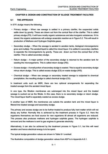
CHAPTER 6: DESIGN AND CONSTRUCTION OFSLUDGE TREATMENT FACILITIESPart A: EngineeringTable 6.4 Hazen Williams value of C for sludge flowsSource: Metcalf & EddyFigure 6.2 Head loss Multiplication Factor for Different Sludge Types and ConcentrationsThe equations for these curves are simplified as follows where P is the % of sludge solids.k for undigested sludge 0.125P2 - 0.1656P 1.5733k for digested sludge 0.0354P2 - 0.0699P 1.0858The calculations for these friction losses are illustrated in Appendix A 6.3.6.2.2Sludge Pump Types and ApplicationsThere are specific considerations to be borne in mind in the use of different types of pumps forhandling sludge. The relative applicability of these is shown in Table 6.5.The illustrations of the internal arrangements of these are compiled in Figure 6.3 (overleaf) a to dand indexed to serial numbers in Table 6.5 for an easier visual understanding of these. In respect ofimpellers in centrifugal pumpsets, the rotary speed is advised not to exceed 960 rpm especially whenpumping return sludge.6-5
Part A: Engineering6-6Table 6.5 Types of sludge pumps and their applicationCHAPTER 6: DESIGN AND CONSTRUCTION OFSLUDGE TREATMENT FACILITIES
CHAPTER 6: DESIGN AND CONSTRUCTION OFSLUDGE TREATMENT FACILITIESPart A: EngineeringFigure 6.3 a Types of sludge pumps6-7
CHAPTER 6: DESIGN AND CONSTRUCTION OFSLUDGE TREATMENT FACILITIESPart A: EngineeringFigure 6.3 b Types of sludge pumps-continued6-8
CHAPTER 6: DESIGN AND CONSTRUCTION OFSLUDGE TREATMENT FACILITIESPart A: EngineeringFigure 6.3 c Types of sludge pumps-continued6-9
CHAPTER 6: DESIGN AND CONSTRUCTION OFSLUDGE TREATMENT FACILITIESPart A: EngineeringFigure 6.3 d Types of sludge pumps-continued6.2.2.1Centrifugal PumpsCentrifugal pumps (as in notation 3 in Table 6.5 and Figure 6.3 a) for handling sludge must beof the non-clog type. They should be robust and should have easily accessible hand-holes forcleaning. Pumps of the macerator type impeller or additional cutters with a cutting ring wherebystringy rags and other fibrous material can get shredded are preferable. When the specificspeed of the pump is low, non-clog impellers are designed with less number of bladesthan in impellers for handling clear liquids. In pumps of high specific speed, the mixedflow impeller should generally have wide passages. Centrifugal pumps with non-clogimpellers have less efficiency than those of normal design for handling clear liquids. The ratingfor the drive motor has to be selected keeping this in mind. The specific speed of the pump alsoaffects the suction-lift capability of the pump. This can be overcome by selecting a verticalcentrifugal pump to be so installed that the impeller would be adequately submerged always. Theimpellers are best chosen as open impellers or semi open impellers or centrifugal screw impellers.6 - 10
CHAPTER 6: DESIGN AND CONSTRUCTION OFSLUDGE TREATMENT FACILITIESPart A: Engineering6.2.2.2Air-Lift PumpsAir lift pumps (as in notation 1 in Table 6.5 and Figure 6.3 d). These are used in small extendedaeration plants to return the sludge and scum to the aeration tank. Small air bubbles are formed in theliquid, which makes the air-water mixing less dense to get lifted to the discharge point.A compressor / blower supplies the air. Air-lift pumps and ejectors are pumping systems, which arethough inherently inefficient, there are no moving parts inside and hence, their operation is fairlytrouble-free.6.2.2.3 Screw PumpsThese are three major variations of these as under1. Archimedean Screw (as in notation 2 in Table 6.5 and Figure 6.3 c)2. Stator-Rotor or Progressive Cavity (as in notation 6 in Table 6.5 and Figure 6.3 a)3. Centrifugal Screw Impeller (as in notation 10 in Table 6.5 and Figure 6.3 c)In the Archimedean screw pumps, the sludge enters the screw pump by a screw conveyor, whichmoves solids to an open impeller and lifts them to the point of discharge. The submerged lowerbearing is of the enclosed and sealed type and the upper bearing is usually grease-lubricatedwith anti-friction bearing. The discharge rate plotted on x axis and head plotted on y axis will be ahorizontal line in these pumps. In general, these are ideal for return sludge because it permitsincidental additional aeration over the screws and rotates at gentle speeds of just about 20 or 30 rpm.They also permit visual inspection of the sludge.A variation of the screw pump is the stator rotor or progressive cavity pump. The pumping element isa helical rotor of steel. It has a compressible stator or lining inside a cast iron body and is contouredto mesh with the helical rotor. Although the pump has some self-priming capability, the rotor mustnever run dry against the rubber stator. The pump can pump forward or reverse depending uponthe direction of rotation. They are not advised for return sludge as the live organisms will besqueezed in the stator and rotor.The centrifugal screw impeller has a shape of an Archimedean screw with widening diameter ofeach successive spiral. They can be mounted both vertically and horizontally. The impeller weight isusually heavier as compared to other screw pumps. They however, have the advantage of atruly non-clog design and are especially suited for sludge drawal from primary clarifiers because thepossible fibrous materials or rags etc which might get into the clarifier sludge will be gliding over theimpeller screw and are pushed out without choking the impeller. They are also useful in return sludgepumping as the live organisms do not get hit at the impeller or casing surfaces.6.2.2.4Reciprocating PlungerPlunger type pumps (as in notation 5 in Table 6.5 and Figure 6.3 a) have a plunger reciprocatingin a cylinder. A pump can have one or more plungers connected to common crankshaft, therebyobtaining arrangements called simplex, duplex, triplex, etc. Their capacities are of the order of 150 to250 rpm per plunger. The pump speeds should be between 40 to 50 rpm.6 - 11
CHAPTER 6: DESIGN AND CONSTRUCTION OFSLUDGE TREATMENT FACILITIESPart A: EngineeringThey are self-priming and can usually work well with suction-lifts up to 3m. The suction-lift capabilitydepends on the design of the pump, especially the suction valve. The pumps can develop highheads and are hence, suitable where accumulation of grease in piping can cause progressiveincrease in head.However, if the delivery piping is likely to get choked, the pumps may develop very high pressuresand this can cause a burst. A relief valve is provided to protect the pump in case of a cloggeddelivery piping after each use. The pump should be flushed so that no solids settle in the cylinderwhich could damage the pump during the next start. The suction and delivery valves are the mainsource of trouble. The valves should be easily accessible for quick cleaning, in case the valvesfail to seat properly.6.2.2.5Diaphragm PumpsThe diaphragm pumps (as in notation 4 & 9 in Table 6.5 and Figure 6.3 b) have a flexiblediaphragm, usually of rubber and actuated by a reciprocating movement. They can be either a singlediaphragm or double diaphragm type.The diaphragm is fastened peripherally to the casing, which also houses the suction and deliveryvalves. The interesting feature of the diaphragm pumps is that the components of the reciprocatingmechanism, which are most prone to wear, are isolated from the path of the sludge. Pneumatic orhydraulic drives can also be employed for the reciprocating movement. These are suited forintermittent pumping of primary clarifier sludge.6.2.2.6Torque Flow PumpsThe torque flow pumps (as in notation 11 in Table 6.5 and Figure 6.3 a) can handle solids up tothe full delivery bore size on the discharge side. The energy imparted to the liquid is by theprinciple of hydro-dynamic liquid coupling The shape of the impeller helps to generate thenecessary swirl inside the casing and this acts as a pumping impeller component.It is stated as a non-clog concept in pumping. In essence, the sludge that is drawn on the suctionside is made to pick up the energy and glide around the inside of the volute before going out withthe delivery head.6.2.2.7Rotary Lobe pumpsRotary Lobe Pumps (as in notation 8 in Table 6.5 and Figure 6.3 c). Liquid flows around theinterior of the casing, but without making contact. This is prevented by external timing gearslocated in the gearbox. Pump shaft support bearings are located in the gearbox, and since thebearings are out of the pumped liquid, pressure is limited by bearing location and shaft deflection.As the lobes come out of mesh, they create expanding volume on the inlet side of the pump. Liquidflows into the cavity and is trapped by the lobes as they rotate. Liquid travels around the interior of thecasing in the pockets between the lobes and the casing. The liquid does not pass between the lobes.The meshing of the lobes forces the liquid through the outlet port under pressure.6 - 12
CHAPTER 6: DESIGN AND CONSTRUCTION OFSLUDGE TREATMENT FACILITIESPart A: Engineering6.2.2.8Operational ProblemsThe gases like Hydrogen Sulphide often get liberated when the sludge, particularly the digestedsludge, is subjected to suction. This hampers the proper operation of the pump. The pumps shouldbe installed, as far as possible, with positive suction. If the suction arrangements are improperlydesigned, a vortex-cone or sink developing in the sludge blanket will cause the watery sludge orsupernatant to be drawn instead of the sludge.The suction pipe should not be too long, nor should the pumping be too long or too fast. It is betterto pump more often than at reduced speed. When a pump is equipped with variable speed drive,it can be started at a relatively high speed and the speed can then be reduced.Sludge from two settling tanks should not be connected to the suction of a common pump. Thesettling tank with the thinner sludge will get pumped and the thickened sludge in the other tankwill not get pumped. Similar problem will happen, if the suction lines from the two tanks will havedifferential frictional losses.The tank with higher frictional loss in its suction piping, which may be because of more length orbecause of choking, will not get pumped. The capacity of sludge pumps is required to be regulatedaccording to the sewage load. Further, variable speed drives are more appropriate for regulationbecause delivery valves present in the sludge pumping system makes the system inefficient andprone to trouble.6.2.2.9Requirement of Standby UnitsThe number of pumping units required including the standby is determined by several factors likethe particular function involved, the size of the plant and the arrangement of the units, especiallyhaving combination of more than one function. A standby capacity of 16 hours in 2 shifts,7 days working 100% standby is recommended wherever mechanical thickening and mechanicaldewatering is practised. However, these standby units are not required for gravity thickening withpicket fence. Since sludge pumping is an important function, standby pumps are provided in equalnumbers or by such arrangement that permits dual duty. The scum is usually mixed with primarysludge and pumped.6.2.2.10Pump AppurtenancesThe performance of the sludge pumps can be more efficient and their control can be better ifvarious appurtenances such as air chambers, sampling devices, measuring devices, valves, gaugesare incorporated in the system and facilities such as revolution counters, gland seals, time clocks,etc., are kept available at the plant.6.2.2.10.1Air ChamberAn air chamber of adequate size is necessary for all plunger type sludge pumps on the dischargeside of the pump as well as the suction side of the pumps, particularly where positive suction headexists. Such chambers absorb the shock of plunger pump pulsations.6 - 13
CHAPTER 6: DESIGN AND CONSTRUCTION OFSLUDGE TREATMENT FACILITIESPart A: Engineering6.2.2.10.2Revolution CounterPlunger-type sludge pumps should be equipped with revolution counters or integrating recordersto help the operator to determine the quantity of sludge pumped in duplicate pump installations.These pumps aid in equalizing the service and wear of each pump.6.2.2.10.3Gland SealsIn the case of centrifugal pumps, external sealing is provided in the stuffing box to prevent theingress of air into the pump. The external sealing may be grease seal or water seal. The water seals arepreferable, as it helps the grit and dirt to be washed away. The water to the water-seal has to bepotable water. However, the connection of potable water should not be taken directly from supply lines.6.2.2.10.4ValvesWhen a dry pit pump has positive suction head in the wet well, there should be an isolating valve.Usually a gate-valve or a knife edge valve on the suction line, is used to facilitate isolating thepump for maintenance. On the delivery side of centrifugal pumps, a non-return valve is necessary, sothat the pump would not experience the back-pressure from the delivery head when the pump hasto be switched off. To minimize the pressure-drop across the valve during the running of the pump,the non-return valve should be of the swing-check or the ball-check type.To avoid water-hammer, which is likely to be caused by the closure of the valve, the valve may beprovided with an anti-slam device, either of the lever and dead-weight type or of the spring-loadingtype or of the dash pot type. Dual check valves are sometimes used, which gives more consistentoperation and facilitates for the use of the pump as metering device. All the valves may be providedwith drain plugs. In larger size plants, where pumps may run in parallel operation with differentpermutation of the standbys, isolation valves are required to isolate those pumps that may be idle.All valves should preferably be of the rising stem type, since they offer the advantage of visualindication of the valve-position.For exterior underground locations, gate valves are generally used. Underground sludge valvesshould be avoided as far as possible by taking advantage of the hydrostatic pressure for sludgewithdrawal through a slant pipe and valve.6.2.2.10.5GaugesPressure gauges should be provided on both the suction and delivery sides. For pumps havingsuction lift, the gauge on the suction side should be a composite vacuum-pressure gauge. Thegauges should be with a cast iron bowl and an oil-resistant rubber diaphragm to keep the sludgeaway from the finer working parts of the gauges.6.2.2.10.6Sampling DevicesAll sludge pumps shall be provided with sampling taps either within themselves or in the pipingadjacent to the pump. These are usually plug valves, normally of size NS 40. Plug valves are simpleand easy to operate for taking samples.6 - 14
CHAPTER 6: DESIGN AND CONSTRUCTION OFSLUDGE TREATMENT FACILITIESPart A: Engineering6.2.2.10.7Washouts and DrainsWashout or flushing arrangements are provided for sludge pumps to facilitate easy and rapid cleansing.The drains on the pump body should be of ample size to ensure release of pressure and drainage of theliquid. The outlet of the drain should be connected to an adjacent floor drain to keep the floor clean.6.2.2.10.8Time ClocksTime clocks, wired across the magnetic starters or motor leads of sludge pumps can be a valuablehelp to the operators. They help to keep an accurate record of the time taken to run the pump forobserving the preventive maintenance schedules in respect to attending to the lubrication,equalization of wear and tear, etc.6.2.2.10.9Measuring DevicesWhile time clocks and counters are adequate for small plants, supplementary flow-meteringarrangements, such as flow tubes with flushing provisions are used in large plants for measuringand recording the quantities of sludge handling. Magnetic meters are more suitable for sludgemetering. Sludge density meters to be installed in the return sludge line of plants for more than1 mld capacity and an advisory for small plants so that they can install if they want in STPs of lessthan 1 mld capacity.6.2.2.11Pump Drive EquipmentThe prime movers for the pumps are usually the electric motors, which have been discussed in detailin Section 5.12.3 of Chapter 5. It is desirable to use flame-proof motors. I.C. engines can be used forstandby services in the case of failure of electric power. Again, the I.C. engine is better used as primemover for a standby generator than as a prime mover for the pump, because the standby generatorcan then provide the power for lighting and ventilation facilities. Gas engines using sludge gas as fuelwould help not only as a standby power supply facility, but also as an effective energy conservationin the operation of the plants.6.2.3Physical Features of Sludge Piping for PumpsAfter selecting the type of pump, the next important thing is to design the suction and deliverypipelines. The design is based on the sludge pumping rate, the velocity in the pipeline, a layout withminimum bends and a material that is corrosion and abrasion resistant.Sewage sludge flows like a thin plastic material and hence, the formulae for the flow of water are notapplicable. The velocity of flow should be in the critical range above the upper limit of the laminar flowand below the lower limit of the turbulent flow, in order to avoid clogging and deposition of grease,so that the application of the hydraulic formulae for flow of water becomes permissible. In general,velocities between 1.5 and 2.5 m/s are to be considered.The diameter of sludge pipes is important to permit cleaning. Where sludge is drawn intermittently asin primary clarifiers, it is advisable that it should be at least 150 mm for suction drawal and 200 mmfor gravity drawal.6 - 15
CHAPTER 6: DESIGN AND CONSTRUCTION OFSLUDGE TREATMENT FACILITIESPart A: EngineeringProvision shall be mandatorily provided for periodical flushing of the pipeline. This can be madeby inserting a “Y” branch double flanged special and closing the free side of the flange by a knifeedge valve and then another double flange short pipe with blank flange. For flushing the pipeline,first the sludge pump shall be stopped or if it is by gravity, the delivery side valve should be closed.Thereafter, the delivery side of the service line of the plant air compressor or a branch line fromthe final treated sewage pump shall be suitably connected to the free flange of the short pipe afterremoving the blank flange. Thereafter, the knife gate valve shall be slowly opened and the air ortreated sewage gradually allowed to dislodge any choked sludge back into the clarifier.For smaller STPs the single diaphragm sludge pump arrangement can be used to advantage. Inorder to take care of thin sludge to flow by gravity for short distances within the STP, a 3% or greaterslope should be adopted.The suction and discharge piping shall be arranged in such a way that their lengths are as short aspossible, straight and with minimum bends. Adequate provision shall be made to facilitate cleaning.Large radius elbows and sweep tees are usually adopted for change in direction. High points shouldbe avoided, as far as possible, to prevent gas pockets. Suitable recess and sleeves are usuallyprovided for all pipes passing through masonry. Double-flanged pipes are usually adopted forsludge lines with at least one 45 degrees double flanged joint in the line for easy dismantling andreassembling. Valves shall be provided at selected locations to clean the lines.6.2.4Adverse Effects of Heavy Metals and Sludge Components on Unit ProcessesHeavy metals may have adverse effects upon the sludge digestion which is a biological process. Ifconcentrations of certain materials (e.g., ammonia, heavy metals, light metal cations and sulphide)increase significantly, they can create unstable conditions in the anaerobic digester. A shock load ofsuch materials in the plant influent or a sudden change in digester operation (e.g., overfeeding solidsor adding excessive chemicals) can create toxic conditions in the digester.Typically, excess concentrations of such toxicants inhibit methane formation, which leads tovolatile acid accumulation, pH depression and digester upset. Depending on the concentrationand type of toxics, the effect can be acute (e.g., instant process failure) or chronic (e.g., depressedperformance). Chemicals can control the concentrations of dissolved toxics (e.g., using iron saltsto control sulphide). A sound monitoring and control programme, and an understanding of toxicagents, can greatly improve the design of mitigation systems.6.2.5Sludge Digestion or Stabilization Requirements including Appropriate Pathogen andVector Attraction ReductionProcesses that significantly reduce pathogen levels in sludge include aerobic and anaerobicdigestion, air drying, alkaline stabilization and composting. Processes that further reducepathogens include Beta or Gamma ray irradiation, composting, heat drying, heat treatment,pasteurization and thermophilic anaerobic digestion.The STPs typically use the following four processes to reduce pathogen level in sludge.6 - 16
CHAPTER 6: DESIGN AND CONSTRUCTION OFSLUDGE TREATMENT FACILITIESPart A: Engineering1) Heat drying2) Aerobic and anaerobic digestion3) Composting4) Alkaline stabilizationThe pathogens in sludge pose risk only if there are routes by which these come into contact withhumans or animals. The route for transport of pathogens is transmission by vectors such as insects,rodents and birds. These are capable of transmitting a pathogen from one organism to another eithermechanically (by simply transporting the pathogen) or biologically by playing a specific role in the lifecycle of the pathogen. Suitable methods for measuring vector attraction directly are not available.Vector attraction reduction is accomplished by employing one of the following:i. Biological processes which breakdown volatile solids and thereby reducing the available foodnutrients for microbial activities and odour potentialii. Chemical or physical conditions that stop microbial activityiii. Physical barriers between vectors and volatile solids in the sewage sludge6.2.6Return Flow Treatment RequirementsThe thickened centrate, digested supernatant liquor, dewatered filtrate, etc., generated in each sludgetreatment process are known by the general name “return flow” and this return flow is generallyreturned to the STP and treated. In this case, the water quality that requires to be checked in thereturn flow generated in each treatment stage is as follows:1) Thickening: SS, nitrogen, phosphorous2) Anaerobic digestion: Nitrogen, phosphorous, COD3) Dewatering: although the items vary depending on the treatment process up to dewatering, thedigestion process exi
The friction loss in gravity pipelines and pumped pipelines are calculated as follows. 6.2.1.1 Friction losses in Gravity Sludge Pipelines 1. Calculate friction loss using Manning’s formula as though it is flowing with water. 2. This friction loss is mult