Transcription
www.inl.govDC Fast Charging Infrastructure50 kW to 350 kWBarney CarlsonIdaho National LaboratoryEnergy Storage & Advanced VehiclesINL/CON-16-39573
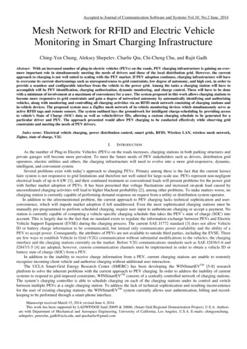
INL’s Electric Vehicle Infrastructure (EVI) Lab Testing and evaluation results from advancedcharging systems supports:– Support codes and standards developmentand harmonization– Grid modernization initiative Measurement evaluation metrics System efficiency EM-field emissions Power quality Response to dynamic grid events Cyber security vulnerability assessment Wide range of grid input powero from 120 VAC to 480 VAC 3φo 400 kVA total capability Sub-system and full vehicle testing rtscene pano51412
Current Technology: DC Fast charging CHAdeMO and SAE CCS– 50 kW power transfer 480 VAC 3φ 75 A circuitSAE J1772 / CCS3
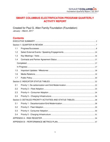
Current Technology: DC Fast charging Tesla Super Charger Network– 120 kW power transfer to each vehicle– Charging complex(up to 8 Super Chargers at one site location) 500 kVA from 12.5 kV utility electric grid feed Stepped down at site to 480 VAC 3φ (600 A)Pocatello, IDphoto courtesy of Jim Francfort4
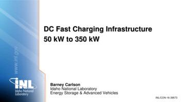
Test Results: DC Fast charging ABB Terra 53 CJ while charging a 2015 Nissan LeafConstant Current Mode– 92.3% AC to DC efficiency– -0.98 Power Factor– 11.0% input current THD– 6.1% Phase current df/evse/ABBDCFCFactSheetJune2016.pdf5
Current Technology: DC Fast chargingINL’s test results: ABB Terra 53 CJ while charging a 2015 Nissan Leaf– Moderate phase to phase unbalance measured duringconstant current se/ABBDCFCFactSheetJune2016.pdf6
Current Technology: DC Fast chargingINL’s test results: ABB Terra 53 CJ while charging a 2015 Nissan se/ABBDCFCFactSheetJune2016.pdf7
Future Technology: Extreme Fast Charging Extreme Fast Charging (XFC)– Goal: charge in 10 minutes 150 kW to 350 kW– For comparison: gasoline refueling 10 gallons in 1 minute ( 20,000 kW and 330 kWh) Infrastructure requirements (each XFC)– 480 VAC 3φ– 225 A to 525 A circuit (150 to 350 kW)8
Future Technology: Extreme Fast Charging Discrete circuit breaker and wiring sizes may limit / discretize the power level choice– Available breaker examples: 400A, 500A, 600A, etc. Potential issues– Distance / availability of 12 kV grid feed near the site– Mass of the charge cord and connector– Standardization (CHAdeMO, SAE CCS, Tesla, etc.)– Cost: component costs, installation costs, demand charges, etc. CHAdeMO and CCS– 150 kW (350A DC) charging standards in progress / near completion First CHAdeMO 150kW installations expected in 2017– Both CHAdeMO and CCS are working towards 350 kW9
Recharge Rates of Various Methods Recharge Rate– Currently up to 120 kW 6 mile/min Refuel rate for liquid fuel is limitedby EPA to 10 gal/min (40 CFR 80.22)– 300 mile/min Proposed 350 kW fast charge– 20 mile/min10
Mass of Charger Connector and Cable As charge power increases currentand conductor size increases– Conductor size per NFPA 70E– Lifting mass limitation (OHSA) 50 lbs. for one person– Higher battery voltage: reduced charge currentand therefore reducedcable size and mass impacts all other vehiclehigh voltage componentrequirements11
Connector and Cable Cooling With active cooling of the cable and connector– Pros: Smaller wire gauge and connector Reduced size, mass, cable stiffness– Cons: Resistive losses increase with smaller wire gauge Cooling system power Total system cost higher Tesla published patents on cooling for charger connector and cable12
Summary INL’s test results shows:– CHAdeMO DC Fast charger 50 kW input power 92% efficiency 0.98 Power Factor Ongoing effort to study the feasibility of Extreme Fast Charging– Goal: charge in 10 minutes– 150 kW to 350 kW13
AcknowledgementThis work is supported bythe U.S. Department of Energy’sEERE Vehicle Technologies ProgramMore Informationhttp://avt.inl.govhttp://at.inl.gov
www.inl.gov DC Fast Charging Infrastructure 50 kW to 350 kW Barney Carlson Idaho National Laboratory . Energy Storage & Advanced Vehicles . INL/CON-16-39573