Transcription
Accepted to Journal of Communication Software and Systems Vol.10. No.2 June, 2014Mesh Network for RFID and Electric VehicleMonitoring in Smart Charging InfrastructureChing-Yen Chung, Aleksey Shepelev, Charlie Qiu, Chi-Cheng Chu, and Rajit GadhAbstract: With an increased number of plug-in electric vehicles (PEVs) on the roads, PEV charging infrastructure is gaining an evermore important role in simultaneously meeting the needs of drivers and those of the local distribution grid. However, the currentapproach to charging is not well suited to scaling with the PEV market. If PEV adoption continues, charging infrastructure will haveto overcome its current shortcomings such as unresponsiveness to grid constraints, low degree of autonomy, and high cost, in order toprovide a seamless and configurable interface from the vehicle to the power grid. Among the tasks a charging station will have toaccomplish will be PEV identification, charging authorization, dynamic monitoring, and charge control. These will have to be donewith a minimum of involvement at a maximum of convenience for a user. The system proposed in this work allows charging stations tobecome more responsive to grid constraints and gain a degree of networked autonomy by automatically identifying and authorizingvehicles, along with monitoring and controlling all charging activities via an RFID mesh network consisting of charging stations andin-vehicle devices. The proposed system uses a ZigBee mesh network of in-vehicle monitoring devices which simultaneously serve asactive RFID tags and remote sensors. The system outlined lays the groundwork for intelligent charge-scheduling by providing accessto vehicle’s State of Charge (SOC) data as well as vehicle/driver IDs, allowing a custom charging schedule to be generated for aparticular driver and PEV. The approach presented would allow PEV charging to be conducted effectively while observing gridconstraints and meeting the needs of PEV drivers.Index terms: Electrical vehicle charging, power distribution control, smart grids, RFID, Wireless LAN, wireless mesh network,Zigbee, state of charge, V2GI.INTRODUCTIONAs the number of Plug-in Electric Vehicles (PEVs) on the roads increases, charging stations in both parking structures andprivate garages will become more prevalent. To meet the future needs of PEV stakeholders such as drivers, distribution gridoperators, electric utilities and others, the charging infrastructure will need to evolve into a more grid-responsive, dynamic,intelligent, and convenient system.Several problems exist with today’s approach to charging PEVs. Primary among these is the fact that the current laissezfaire system is not responsive to grid limitations and therefore not well suited for large-scale use. PEVs represent non-negligentelectrical loads of up to 6 kW [1], and their continued treatment as conventional loads will present problems for the power gridwith further market adoption of PEVs. It has been presented that voltage fluctuations and increased on-peak load caused byuncoordinated charging activities will lead to higher blackout probability [2], among other problems. To make matters worse, nocharging station is currently capable of performing demand-response on request from a utility or distribution system operator.In addition to the aforementioned problem, the current approach to PEV charging lacks technical sophistication and userconvenience, which will impede market adoption if left unaddressed. Even the most sophisticated charging stations must bemanually pre-programmed to perform scheduled charging, require user input to authenticate charging or accept a payment. Nostation is currently capable of computing a vehicle-specific charging schedule that takes the PEV’s state of charge (SOC) intoaccount. This is largely due to the fact that no standard exists to regulate the information exchange between PEVs and ElectricVehicle Support Equipment (EVSE) during the charging process. The current SAE J1772 standard [3] does not allow VehicleID or battery charge information to be communicated, but instead only communicates power availability and the ability of aPEV to accept power. Consequently, the attributes of PEVs are not available to outside third parties, including the EVSE. Thereare few ways to establish Vehicle to Grid (V2G) communication without substantial modifications to the vehicles, the charginginterface and the charging stations currently on the market. Before V2G communications standards such as SAE J2836/1-6 andJ2847/1-5 [4] are adopted, however, custom communication channels must be implemented in order to obtain a vehicle ID orbattery state of charge (SOC) from a PEV.In addition to the inability to receive charge information from a PEV, current charging stations are unable to remotelyrecognize incoming client vehicle and authorize charging without additional user interaction.The UCLA Smart-Grid Energy Research Center (SMERC) has been developing the WINSmartEVTM [5-8] researchplatform to solve the inherent problems with the current approach to PEV charging. In order to address the inability of currentsystems to respond to grid-imposed constraints, WINSmartEVTM consists of a centrally controlled network of charging stations.The system’s charging controller is able to schedule charging on each of the charging stations under its control and switchbetween multiple PEVs at a single charging station. To address the lack of technical sophistication and resulting inconveniencefor the user of existing charging stations, the WINSmartEVTM system currently allows user authentication, billing and recordkeeping to be performed through a smart-phone interface.Manuscript received March 15, 2014; revised June 4, 2014.This work has been supported by LADWP/DOE fund 20699 & 20686, (Smart Grid Regional Demonstration Project), U.S.A. Authorsare with Department of Mechanical and Aerospace Engineering, University of California, Los Angeles, U.S.A. E-mails: chingyenchung,ashepelev, peterchu, gadh@ucla.edu, and qiucharlie@gmail.com
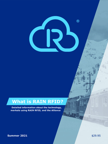
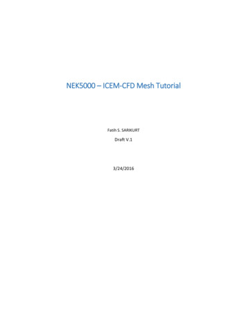
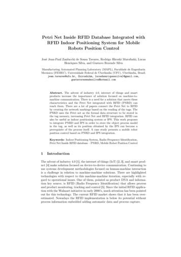
Accepted to Journal of Communication Software and Systems Vol.10. No.2 June, 2014The current WINSmartEVTM infrastructure is the first step in achieving a grid-responsive, intelligent, and convenientcharging system. The improvements presented in this paper represent the next step forward. In order to allow theWINSmartEVTM charging controller to derive a vehicle-specific charging schedule that takes both the vehicle’s SOC, driverpreferences, and the grid load into account, we propose a solution for remotely monitoring the SOC throughout the chargingprocess by using in-vehicle monitoring devices called Vehicle Monitoring/Identification Modules (VMMs).In order to simplify user interactions and make charging more convenient, we propose a solution for remotelyauthenticating and authorizing vehicles for charging using the same VMM devices. Unlike traditional point of sale (POS)devices used in un-networked charging stations or short range RFID cards used in networked stations [9-10], no extraauthorization step is required on the part of the user. No passive RFID tags or readers are used in the proposed solution.Communicating through a ZigBee mesh network, VMMs serve the purpose of active RFID tags for vehicle identification andcharging authorization. These devices allow charging authorization to take place seamlessly at multiple charging stations withinwireless signal range. The VMMs communicate directly with the control center through a ZigBee mesh network, thussimplifying the system and eliminating the need for layered architecture to manage a variety of automatic identificationhardware [11].This paper is structured in the order outlined below. First, the design of the existing WINSmartEV TM system is presented indetail. Afterwards, each of the proposed updates including remote charge-monitoring and remote charging authorization isdescribed in detail. Finally, results of the implementation and experimental results of system function and performance arepresented and discussed.II.EXISTING WINSMARTEVTM SYSTEMWINSmartEVTM is a centrally controlled and networked charging system that allows up to four PEVs to be charged at asingle charging station at any one time, as shown in Fig. 1. Each of the four PEVs at a single station may be charged at a uniquepower level. This system takes the first step towards grid-responsive and vehicle-specific charging control by allowing acharging controller to monitor and regulate all charging stations on its network.Figure 1. Four-channel smart charging station with EVsIn addition to networked charging control and variable-current multiplexed charging, WINSmartEVTM adds a host offeatures aimed at increasing user-friendliness and convenience. The system employs a mobile app that allows an authorized userto check a list of available charging stations, remotely start or stop PEV charging, check charging status, view monthly chargingrecords, and manage his/her account via a mobile device. Fig 2 shows the mobile interface.Figure 2. WINSmartEVTM Mobile appThe WINSmartEVTM system hardware consists of a server-based aggregate control center, communication network andmultiple smart-charging stations. The architecture is illustrated in Fig. 3.
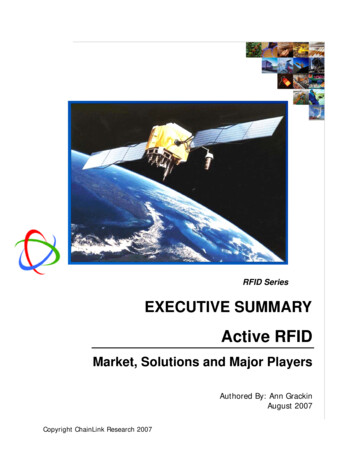
Accepted to Journal of Communication Software and Systems Vol.10. No.2 June, 2014Figure 3. WINSmartEVTM ArchitectureA. Aggregate charging controllerThe server-based aggregate charging control system consists of a station and vehicle database, station controller, a systemadministrator’s control interface, and a user control interface. The database contains data about all charging stations and electricvehicles on the WINSmartEVTM network. The station controller initiates and terminates charging activities based on vehicleavailability and user or administrator commands. The administrator’s control interface, shown in Fig. 4, allows individualstations to be monitored and manually controlled by a system administrator. The user control interface allows a user to controlcharging of their PEV through the mobile interface shown in Fig. 2.Figure 4. Screenshot of Monitoring and Control CenterB. Communication networkThe charging controller communicates with all WINSmartEVTM charging stations through a network consisting of wirelessand wired connections. Ethernet is used where a wired connection is practical. In more remote locations, 3G wirelesscommunication is used. If multiple charging stations are located within close signal range, a ZigBee wireless network isestablished between them and a single station acts as a communication link with the central controller. In certain cases, PowerLine Communication (PLC) is used to establish communication between stations located too far for a ZigBee network and awayfrom any available Ethernet ports.C. Charging stationsThe charging stations consist of a 3G wireless gateway, a control unit, and current meters with controllable relays as shownin Fig. 5. ZigBee is used for communication between the gateway, the control unit and the current meters. If multiple stationsare within close geographic proximity, only one station is equipped with a 3G gateway. The rest receive controller commandsrelayed through the 3G-equipped station.
Accepted to Journal of Communication Software and Systems Vol.10. No.2 June, 2014Figure 5.Details of smart charging stationIII.PROPOSED SYSTEMWhile the current WINSmartEVTM system builds a strong foundation for a networked charging system that is intelligent,flexible and responsive to grid limitations, there are tangible opportunities for further development. For example, the existingsystem does not account for a PEV’s instantaneous state of charge or its driver’s typical driving cycle when scheduling charging,leading to less-than-optimal scheduling. Furthermore, opportunities exist to further improve user convenience by limiting thenumber of steps the user has to complete before charging their vehicle.The proposed system addresses many shortcomings of the existing WINSmartEV TM architecture by implementing the prerequisite hardware what will allow the charging controller to prioritize PEV charging according to an individual vehicle’s chargestate and a driver’s typical commute. In addition, the new system allows arriving vehicles to be identified and authorized forcharging without any actions on the part of the user. These improvements allow the WINSmartEVTM system to gain a level ofsophistication that allows it to become more responsive to the needs of the grid while meeting the convenience needs of PEVdrivers. In addition, these new capabilities have been achieved with few changes in system architecture, require minimaladditional investment and do not involve any modifications to a PEV’s factory charging interface.The new charge monitoring and control capability as well as the remote authentication capability is achieved with threeadditional hardware components: an in-Vehicle Monitoring/Identification Module (VMM) [14], a ZigBee wireless networkcoordinator and a pilot-signal monitor located in each charging station for PEV plug-in detection.Vehicle Monitoring/Identification Modules (VMM) act as RFID tags [13] for vehicle or driver identification, chargingauthorization, and charge monitoring. These devices allow charging authorization to take place seamlessly at multiple chargingstations within wireless signal range and transmit the state of charge and other PEV information on request from a controller.The ZigBee wireless network coordinator allows multiple vehicles and charging stations to establish a wireless network andcommunicate with the server-based charging controller. The coordinator establishes a ZigBee network and relays messages fromthe control center to each charging station belonging to the local ZigBee network.PEV pilot-signal monitor is located in each charging station and monitors the pilot signal voltage in order to detect thepresence and status of the PEV at the given station.A.Vehicle Monitoring/Identification Module (VMM)The VMM has the capability of monitoring the state of the PEV through the vehicle’s CAN bus and uniquely identifyingeach PEV by its 64-bit ZigBee MAC address. The module is consequently an active RFID tag and a remote sensor with theability to provide SOC, battery voltage, battery temperature and other information. The schematic and a cutaway view of theVMM are shown in Fig. 6.
Accepted to Journal of Communication Software and Systems Vol.10. No.2 June, 2014Figure 6. Schematic and cutaway view of VMM [13]For communication on the mesh network, the device employs a Texas Instrument ZigBee board equipped with an MSP430microcontroller and a CC2530 RF transceiver. These devices are configured to act as a ZigBee router. The device uses anMCP2551 CAN transceiver and an ATMega328P microprocessor to monitor the PEV’s CAN bus. The firmware flow ofMSP430 is shown in Fig. 7.Figure 7. ZigBee firmware flow in the VMM [14]The firmware on the MSP430 is responsible for many tasks including establishing a connection with the ZigBeecoordinator, responding to ID and data requests, and maintaining the connection through a periodic handshake. The timerinterrupt logic in the lower right corner of Fig. 7 is used to ensure connectivity with the coordinator. The interrupt keeps arunning time count and sets flags that are used in the main loop to issue handshake massage. The firmware restarts the node if noresponse is received to the handshake in an attempt to re-establish a lost connection.Fig. 8 shows the ATMega328P firmware logic flowchart of the VMM. This microcontroller is the interface between theMCP2551 CAN Transceiver and the ZigBee router.
Accepted to Journal of Communication Software and Systems Vol.10. No.2 June, 2014StartInitializeAtmega328 andMCP2551NReceived SOCrequest?Begin main loopYDecode message,send SOC to ZigBeenodeTimeout?YNMessagecontains SOC?YNReceived CANmessage?Figure 8. VMM microcontroller ATMega328P firmware flow [14]Whenever a command to retrieve data is received from the MSP430, the program on ATMega328P listens for the correctmessage on the CAN bus, decodes it, and transmits the information back to the MSP430. The MSP430 then transmits the dataon the ZigBee network to the coordinator node.In addition to the ability of the VMM to monitor vehicle states, it may be used as a supplemental solution to detect faults inthe EVSE. Integrated power consumption data from the EVSE may be compared to the incremental SOC change of the PEV.Significant differences in readings would indicate faults in the current-metering circuit.B. RFID Reader: ZigBee CoordinatorThe ZigBee coordinator, located in the master EVSE, serves as the RFID reader, sets up the ZigBee network and handlesmessages between the gateway and the end devices/routers. When a ZigBee end device/router joins the mesh network, thecoordinator assigns it a 16 bits dynamic address and associates the dynamic address with the unique MAC address of the ZigBeedevice. These identifiers are used to correctly route messages as well as for PEV charge authorization. The coordinatorimplementation consists of a TI CC2530ZNP, a MAX3232 level shifter for serial I/O, and a voltage regulator, as shown in Fig.9.Figure 9. ZigBee coordinator implementation [13]In order to ensure a stable connection with each ZigBee device on the network, a handshake protocol has beenimplemented between the coordinator and routers, as summarized in Table I.TABLE I.CommandRequestZIGBEE HANDSHAKE est[MAC address]”
Accepted to Journal of Communication Software and Systems Vol.10. No.2 June, 2014ResponseZigBeecoordinator“comdresp[MAC address]”An approaching or departing PEV is recognized by the coordinator using the Received Signal Strength Indication (RSSI)from the VMMs. Fig. 10 shows the firmware flow of the ZigBee coordinator.Figure 10. ZigBee coordinator firmware flow [13]C. Charging Authentication with RFIDSeveral processes are involved in PEV charging authentication via RFID , including ZigBee MAC address retrieval, userauthorization, and PEV plug-in status detection. Fig. 11 shows a flowchart of the authentication process.
Accepted to Journal of Communication Software and Systems Vol.10. No.2 June, 2014Figure 11. Charging authentication process using RFID [13]New PEV arrivals are checked periodically. The server sends out the “rgst” command to check if new tag IDs have beenregistered after RFID reader initialization. The “stat” command is later sent out to identify which charging station a newlyarrived PEV is plugged into. If the tag ID corresponds to an authorized user account in the database, the command to enablecharging is sent out to begin PEV charging. All commands are in the following text-based format:comd[command][channel][parameter]. Details of the command and return values are summarized in Table II.TABLE II.CommandrgstCOMMANDS OF THE CHARGING STATIONDescription and ExampleReturn all registered ZigBee MAC addresscomdrgst0000[return]:rgst01[MAC address][approach/leave/stay]rgst02[MAC address][approach/leave/stay]statCharging station status requestcomdstat0100request channel 1 status[return]:duty0150rely0101plug0101stat0100The aggregate charging server uses EV plug-in status detection to identify the presence of a PEV at a charging station andto associate the vehicle’s ID with a particular charging receptacle. The PEV plug-in status is monitored on the pilot signalgenerator/monitor circuit by detecting pilot signal voltage levels set by the PEV. The pilot signal generator circuit is shown inFig. 12.
Accepted to Journal of Communication Software and Systems Vol.10. No.2 June, 2014Figure 12. Implementation of the control unit: (1) Pilot Signal Generator(2) Pilot Signal Monitor (3) 555 counter. (4) Relay Driver. (5)Schmitt Trigger. (6) Unit Gain Buffer. (7) Inverting Amplifier. (8 )Inverting LPF [13]The pilot signal generator consists of a Pulse Width Modulation (PWM) signal generator and a Schmitt trigger-basedamplifier. APWM signal is produced, amplified, and transmitted to the PEV. The PEV clips the PWM amplitude, and themodified signal is watched by the pilot-signal monitor residing on the same circuit. The monitor consists of a de-amplifier andlow-pass filter that produces a DC voltage within AD converter range.PEV plug-in status detection is executed in the firmware-based state machine on the pilot signal monitor. The statemachine firmware flow is shown in Fig. 13.Figure 13. State Machine Flow of the Firmware [13]IV.EXPERIMENTS AND RESULTSThree charging stations using the new ZigBee based authentication and monitoring system are currently deployed on theUCLA campus as shown in Fig. 14.
Accepted to Journal of Communication Software and Systems Vol.10. No.2 June, 2014Figure 14. Map of system-compatible charging stations on UCLA campus [14]In order to design a functional controller for this system, the communication delays and RFID response times must beunderstood. In addition, PEV plug-in status detection and RSSI test results must be examined to ensure the functionality of thesystem. Fig. 15 shows the setup of the experiments in a Nissan Leaf PEV.Figure 15. Experimental setup in Nissan Leaf [13]Experimental results including communication delays, RSSI, and PEV plug-in status detection are presented in thefollowing subsections.A. Communication Delays and Response TimeThere are two major time delays in the system: the ZigBee request and response delay and the CAN-bus monitoring delay.The local controller will have to wait T wait to get the response to a data query in (1).Twait TZigBee TCAN read TZigBee Forward TZigBee Re verse TCAN read(1)Experimental results of the ZigBee router response times and CAN-bus read times are presented below.1) ZigBee Router Reponse TimeThe distribution of response time for one-hop communication between a coordinator and a router are shown in Fig. 16.
Accepted to Journal of Communication Software and Systems Vol.10. No.2 June, 2014Figure 16. ZigBee router response times in 30 trial runs [13]The result shows a considerable variation in router response times with an average delay around 1.4 seconds. In this case, atwo second minimum interval must be incorporated to allow for message response. However, it is very likely that more than onehop would be required to transfer data because a mesh network is involved. The distribution of response time for two-hopcommunication between a coordinator and a router through a router/repeater are presented in Fig. 17.Figure 17. Two-hop ZigBee router response times in 30 trial runs [14]The distribution of two-hop communication again varies between 1 and 2 seconds with an average of 1.5 seconds. Notice thatthe response times are all multiples of 0.5 seconds, which is likely due to a delay on the intermediate router.2) CAN-bus Reading TimesBecause the CAN standard includes automatic message arbitration that forces non-critical message to wait until messageswith higher priority have been transmitted, the CAN-bus read delay is not a constant but varies in time from vehicle to vehicle,and between the specific messages. In practice, messages with different priority result in variable transmission rates. Thedistribution of time to read the SOC message on Nissan Leaf CAN bus is shown on Fig. 18.
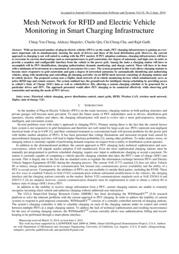
Accepted to Journal of Communication Software and Systems Vol.10. No.2 June, 2014Figure 18. Nissan Leaf CAN bus reading times for 100 trial runs [14]3) Request IntervalIn section IV A., the maximum time for a two-hop response is 2 seconds, which means T ZigBee has maximum value of 2seconds. Considering TCAN read is with maximum value of 0.1 second, T wait will have to be greater than 2.1 seconds per equation(1). As a result, 2.1 second minimum waiting interval must be incorporated on the local controller. Therefore, an interval muchlarger than 2.1 seconds needs to be incorporated for detecting an approaching PEV. Taking 3G communication delay presentedin [12] into account, the maximum round trip time of 3G is around 5 seconds, which means the server will need to wait 7.1seconds to receive a response to a data request.B. PEV Plug-in Status DetectionAs per J1772 specification, the duty cycle of the pilot signal indicates available current to the PEV. To ensure the systemworks at varying duty cycles, the DC-converted pilot signal was measured for two distinct PEV states: PEV disconnected andPEV charging. Fig. 19 shows the results of A/D values v.s. duty cycle of pilot signal.Figure 19. A/D Value v.s. Duty Cycle of Pilot Signal [13]The DC values measured at the A/D converter are clearly distinguishable in these two cases and have good linearity. Theresolution is more than sufficient to detect the PEV’s plug-in status even when the duty cycle is around 10%, which indicates a6A charge current, or the minimum current set by J1772 specification. The average value of these two cases is set to be thethreshold value for PEV plug-in status detection.C. Approaching and Leaving DeteminationThe RSSI is used to identify an approaching or departing PEV to and from a charging station. Fig. 20 shows the results ofRSSI vs. distance between the charging station and the PEV.
Accepted to Journal of Communication Software and Systems Vol.10. No.2 June, 2014Figure 20. RSSI v.s. Distance between two charging station and the PEV [13]When the PEV is within 50 meters of the charging station, the RSSI has a sudden jump from -89 dBm to -77dBm, whichmeans the PEV is likely to be detected in this range. Notice that there is another jump in RSSI when the PEV approaches within20 meters, which implies that RSSI would be an appropriate metric for PEV approaching identification.In most cases, the accepted speed limit in parking lot is 5 mph, which means a PEV approaches a charging station by 4.5meters every 2 seconds. Assuming that the PEV parks 5 meters away from the charging station, after a PEV is detected at adistance of 50 meters, the station will have a maximum of 10 handshakes to determine whether the PEV is approaching orleaving.D. Collaboration between Server and StationsThe RFID authentication and authorization control scheme involves collaboration between a master controller (server) and alocal controller (ZigBee coordinator). In the 3G case, we measure status retrieval TRoundTrip distributions of three chargingstations in different locations at UCLA in second, third, fourth charts in Fig. 21. As a baseline the first chart in Fig. 21 showsround trip status retrieval via Ethernet connection.Figure 21. Status Retrieval Round Trip TimeThe experiments show that T3G is not a constant offset from the Ethernet case but a distribution probability with two peaksmeasured in its distribution. In order to accelerate the performance of the system, the local controller will need to be modified topush data to the master controller. Instead of the server periodically sending “rgst” commands to retrieve new tag IDs from theZigBee coordinator, the coordinator will push newly detected tag IDs to the database. Assuming the 3G uplink time is half ofround trip time, the interval of new tag ID detection can be shortened by half. In addition, the traffic between the server and thestation can also be reduced.The local controller inside the charging station sends the trigger signal on change of PEV plug-in status. Once a new PEVplug-in status is detected, the local controller pushes the status and corresponding tag ID to the database. If the tag ID matchesan authorized user account in the database, the command to begin PEV charging is sent.
Accepted to Journal of Communication Software and Systems Vol.10. No.2 June, 2014E. Exception HandlingWhen more than two PEVs arrive at the same charging station around the same time, the charging station may not have a wayto associate their IDs with the corresponding outlets. In this case, the server needs an exception handling process to handle thecharging sessions.If the arriving PEVs have different on-board charger size, the charging station will be able to associate the IDs with outletsdue to differences in charging current. However, if PEVs have same size on board chargers, the server will not be able toassociate the IDs with their respective electrical outlets at the start of charging. The server will still be able to associate thecharging sessions with IDs and outlets when the PEVs leave by detecting PEV’s RSSI. If the PEVs are fully charged before theyleave, the server will associate the IDs and outlets by SOC when PEVs are fully charged. If the PEVs with same size on boardchargers arrive and leave around the same time without fully charged, there is no need to distinguish the charging sessionbecause their drivers will be billed for the same energy consumptionV.CONCLUSIONA convenient method for charge authorization and monitoring is provided by the ZigBee-based system proposed above. Anapproach utilizing a remote identification tag and charging station-based reader allows authorization/identification and chargemonitoring capability to be added to the existing WINSmartEV TM charging infrastructure without excessive modification to thePEV or the charging station. Plug-in VMM modules allow PEVs to be made easily compatible with the system while retainingcompliance with the J1772 standard. Use of a mesh network allows a robust connection to be maintained between chargingstations and PEVs in a real world environment subject to signal blocking conditions. Charge-monitoring capability allows acontroller to access a PEV’s state of charge and facilitates generation of charging schedules tailored to a particular vehicle anddriver.The aforementioned improvements described in this work bring WINSmartEVTM infrastructure closer to an economical anduser friendly smart charging technology that enhances the stability and reliability of the local grid while meeting theco
WINSmartEVTM charging controller to derive a vehicle-specific charging schedule that takes both the vehicle's SOC, driver preferences, and the grid load into account, we propose a solution for remotely monitoring the SOC throughout the charging process by using in-vehicle monitoring devices called Vehicle Monitoring/Identification Modules (VMMs).