Transcription
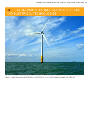
CHAPTER 23 ELECTROMAGNETIC INDUCTION, AC CIRCUITS, AND ELECTRICAL TECHNOLOGIES23 ELECTROMAGNETIC INDUCTION, AC CIRCUITS,AND ELECTRICAL TECHNOLOGIESFigure 23.1 This wind turbine in the Thames Estuary in the UK is an example of induction at work. Wind pushes the blades of the turbine, spinning a shaft attached tomagnets. The magnets spin around a conductive coil, inducing an electric current in the coil, and eventually feeding the electrical grid. (credit: phault, Flickr)813
814CHAPTER 23 ELECTROMAGNETIC INDUCTION, AC CIRCUITS, AND ELECTRICAL TECHNOLOGIESLearning Objectives23.1. Induced Emf and Magnetic Flux Calculate the flux of a uniform magnetic field through a loop of arbitrary orientation. Describe methods to produce an electromotive force (emf) with a magnetic field or magnet and a loop of wire.23.2. Faraday’s Law of Induction: Lenz’s Law Calculate emf, current, and magnetic fields using Faraday’s Law. Explain the physical results of Lenz’s Law23.3. Motional Emf Calculate emf, force, magnetic field, and work due to the motion of an object in a magnetic field.23.4. Eddy Currents and Magnetic Damping Explain the magnitude and direction of an induced eddy current, and the effect this will have on the object it is induced in. Describe several applications of magnetic damping.23.5. Electric Generators Calculate the emf induced in a generator. Calculate the peak emf which can be induced in a particular generator system.23.6. Back Emf Explain what back emf is and how it is induced.23.7. Transformers Explain how a transformer works. Calculate voltage, current, and/or number of turns given the other quantities.23.8. Electrical Safety: Systems and Devices Explain how various modern safety features in electric circuits work, with an emphasis on how induction is employed.23.9. Inductance Calculate the inductance of an inductor. Calculate the energy stored in an inductor. Calculate the emf generated in an inductor.23.10. RL Circuits Calculate the current in an RL circuit after a specified number of characteristic time steps. Calculate the characteristic time of an RL circuit. Sketch the current in an RL circuit over time.23.11. Reactance, Inductive and Capacitive Sketch voltage and current versus time in simple inductive, capacitive, and resistive circuits. Calculate inductive and capacitive reactance. Calculate current and/or voltage in simple inductive, capacitive, and resistive circuits.23.12. RLC Series AC Circuits Calculate the impedance, phase angle, resonant frequency, power, power factor, voltage, and/or current in a RLC series circuit. Draw the circuit diagram for an RLC series circuit. Explain the significance of the resonant frequency.Introduction to Electromagnetic Induction, AC Circuits and Electrical TechnologiesNature’s displays of symmetry are beautiful and alluring. A butterfly’s wings exhibit an appealing symmetry in a complex system. (See Figure 23.2.)The laws of physics display symmetries at the most basic level—these symmetries are a source of wonder and imply deeper meaning. Since weplace a high value on symmetry, we look for it when we explore nature. The remarkable thing is that we find it.Figure 23.2 Physics, like this butterfly, has inherent symmetries. (credit: Thomas Bresson)The hint of symmetry between electricity and magnetism found in the preceding chapter will be elaborated upon in this chapter. Specifically, we knowthat a current creates a magnetic field. If nature is symmetric here, then perhaps a magnetic field can create a current. The Hall effect is a voltagecaused by a magnetic force. That voltage could drive a current. Historically, it was very shortly after Oersted discovered currents cause magneticfields that other scientists asked the following question: Can magnetic fields cause currents? The answer was soon found by experiment to be yes. In1831, some 12 years after Oersted’s discovery, the English scientist Michael Faraday (1791–1862) and the American scientist Joseph Henry(1797–1878) independently demonstrated that magnetic fields can produce currents. The basic process of generating emfs (electromotive force) and,hence, currents with magnetic fields is known as induction; this process is also called magnetic induction to distinguish it from charging by induction,which utilizes the Coulomb force.Today, currents induced by magnetic fields are essential to our technological society. The ubiquitous generator—found in automobiles, on bicycles, innuclear power plants, and so on—uses magnetism to generate current. Other devices that use magnetism to induce currents include pickup coils inelectric guitars, transformers of every size, certain microphones, airport security gates, and damping mechanisms on sensitive chemical balances.Not so familiar perhaps, but important nevertheless, is that the behavior of AC circuits depends strongly on the effect of magnetic fields on currents.This content is available for free at http://cnx.org/content/col11406/1.7
CHAPTER 23 ELECTROMAGNETIC INDUCTION, AC CIRCUITS, AND ELECTRICAL TECHNOLOGIES23.1 Induced Emf and Magnetic FluxThe apparatus used by Faraday to demonstrate that magnetic fields can create currents is illustrated in Figure 23.3. When the switch is closed, amagnetic field is produced in the coil on the top part of the iron ring and transmitted to the coil on the bottom part of the ring. The galvanometer isused to detect any current induced in the coil on the bottom. It was found that each time the switch is closed, the galvanometer detects a current inone direction in the coil on the bottom. (You can also observe this in a physics lab.) Each time the switch is opened, the galvanometer detects acurrent in the opposite direction. Interestingly, if the switch remains closed or open for any length of time, there is no current through thegalvanometer. Closing and opening the switch induces the current. It is the change in magnetic field that creates the current. More basic than thecurrent that flows is the emfthat causes it. The current is a result of an emf induced by a changing magnetic field, whether or not there is a path forcurrent to flow.Figure 23.3 Faraday’s apparatus for demonstrating that a magnetic field can produce a current. A change in the field produced by the top coil induces an emf and, hence, acurrent in the bottom coil. When the switch is opened and closed, the galvanometer registers currents in opposite directions. No current flows through the galvanometer whenthe switch remains closed or open.An experiment easily performed and often done in physics labs is illustrated in Figure 23.4. An emf is induced in the coil when a bar magnet ispushed in and out of it. Emfs of opposite signs are produced by motion in opposite directions, and the emfs are also reversed by reversing poles. Thesame results are produced if the coil is moved rather than the magnet—it is the relative motion that is important. The faster the motion, the greaterthe emf, and there is no emf when the magnet is stationary relative to the coil.Figure 23.4 Movement of a magnet relative to a coil produces emfs as shown. The same emfs are produced if the coil is moved relative to the magnet. The greater the speed,the greater the magnitude of the emf, and the emf is zero when there is no motion.The method of inducing an emf used in most electric generators is shown in Figure 23.5. A coil is rotated in a magnetic field, producing an alternatingcurrent emf, which depends on rotation rate and other factors that will be explored in later sections. Note that the generator is remarkably similar inconstruction to a motor (another symmetry).815
816CHAPTER 23 ELECTROMAGNETIC INDUCTION, AC CIRCUITS, AND ELECTRICAL TECHNOLOGIESFigure 23.5 Rotation of a coil in a magnetic field produces an emf. This is the basic construction of a generator, where work done to turn the coil is converted to electric energy.Note the generator is very similar in construction to a motor.So we see that changing the magnitude or direction of a magnetic field produces an emf. Experiments revealed that there is a crucial quantity calledthe magnetic flux, Φ , given byΦ BA cos θ,where(23.1)B is the magnetic field strength over an area A , at an angle θ with the perpendicular to the area as shown in Figure 23.6. Any change inΦ induces an emf. This process is defined to be electromagnetic induction. Units of magnetic flux Φ are T m 2 . As seen inFigure 23.6, B cos θ B , which is the component of B perpendicular to the area A . Thus magnetic flux is Φ B A , the product of the areamagnetic fluxand the component of the magnetic field perpendicular to it.Figure 23.6 Magnetic fluxan emf.Φis related to the magnetic field and the area over which it exists. The fluxΦ BA cos θis related to induction; any change inΦinducesAll induction, including the examples given so far, arises from some change in magnetic flux Φ . For example, Faraday changed B and hence Φwhen opening and closing the switch in his apparatus (shown in Figure 23.3). This is also true for the bar magnet and coil shown in Figure 23.4.When rotating the coil of a generator, the angle θ and, hence, Φ is changed. Just how great an emf and what direction it takes depend on thechange inΦ and how rapidly the change is made, as examined in the next section.23.2 Faraday’s Law of Induction: Lenz’s LawFaraday’s and Lenz’s LawFaraday’s experiments showed that the emf induced by a change in magnetic flux depends on only a few factors. First, emf is directly proportional tothe change in flux ΔΦ . Second, emf is greatest when the change in time Δt is smallest—that is, emf is inversely proportional to Δt . Finally, if aThis content is available for free at http://cnx.org/content/col11406/1.7
CHAPTER 23 ELECTROMAGNETIC INDUCTION, AC CIRCUITS, AND ELECTRICAL TECHNOLOGIEScoil has N turns, an emf will be produced that isthe emf induced by a change in magnetic flux isN times greater than for a single coil, so that emf is directly proportional to N . The equation foremf N ΔΦ .Δt(23.2)This relationship is known as Faraday’s law of induction. The units for emf are volts, as is usual.The minus sign in Faraday’s law of induction is very important. The minus means that the emf creates a current I and magnetic field B that opposethe change in flux Δ Φ —this is known as Lenz’s law. The direction (given by the minus sign) of the emfis so important that it is called Lenz’s lawafter the Russian Heinrich Lenz (1804–1865), who, like Faraday and Henry,independently investigated aspects of induction. Faraday was aware ofthe direction, but Lenz stated it so clearly that he is credited for its discovery. (See Figure 23.7.)Figure 23.7 (a) When this bar magnet is thrust into the coil, the strength of the magnetic field increases in the coil. The current induced in the coil creates another field, in theopposite direction of the bar magnet’s to oppose the increase. This is one aspect of Lenz’s law—induction opposes any change in flux. (b) and (c) are two other situations.Verify for yourself that the direction of the induced B coil shown indeed opposes the change in flux and that the current direction shown is consistent with RHR-2.Problem-Solving Strategy for Lenz’s LawTo use Lenz’s law to determine the directions of the induced magnetic fields, currents, and emfs:1.2.3.4.5.6.Make a sketch of the situation for use in visualizing and recording directions.Determine the direction of the magnetic field B.Determine whether the flux is increasing or decreasing.Now determine the direction of the induced magnetic field B. It opposes the change in flux by adding or subtracting from the original field.Use RHR-2 to determine the direction of the induced current I that is responsible for the induced magnetic field B.The direction (or polarity) of the induced emf will now drive a current in this direction and can be represented as current emerging from thepositive terminal of the emf and returning to its negative terminal.For practice, apply these steps to the situations shown in Figure 23.7 and to others that are part of the following text material.Applications of Electromagnetic InductionThere are many applications of Faraday’s Law of induction, as we will explore in this chapter and others. At this juncture, let us mention several thathave to do with data storage and magnetic fields. A very important application has to do with audio and video recording tapes. A plastic tape, coatedwith iron oxide, moves past a recording head. This recording head is basically a round iron ring about which is wrapped a coil of wire—anelectromagnet (Figure 23.8). A signal in the form of a varying input current from a microphone or camera goes to the recording head. These signals(which are a function of the signal amplitude and frequency) produce varying magnetic fields at the recording head. As the tape moves past therecording head, the magnetic field orientations of the iron oxide molecules on the tape are changed thus recording the signal. In the playback mode,the magnetized tape is run past another head, similar in structure to the recording head. The different magnetic field orientations of the iron oxidemolecules on the tape induces an emf in the coil of wire in the playback head. This signal then is sent to a loudspeaker or video player.817
818CHAPTER 23 ELECTROMAGNETIC INDUCTION, AC CIRCUITS, AND ELECTRICAL TECHNOLOGIESFigure 23.8 Recording and playback heads used with audio and video magnetic tapes. (credit: Steve Jurvetson)Similar principles apply to computer hard drives, except at a much faster rate. Here recordings are on a coated, spinning disk. Read heads historicallywere made to work on the principle of induction. However, the input information is carried in digital rather than analog form – a series of 0’s or 1’s arewritten upon the spinning hard drive. Today, most hard drive readout devices do not work on the principle of induction, but use a technique known asgiant magnetoresistance. (The discovery that weak changes in a magnetic field in a thin film of iron and chromium could bring about much largerchanges in electrical resistance was one of the first large successes of nanotechnology.) Another application of induction is found on the magneticstripe on the back of your personal credit card as used at the grocery store or the ATM machine. This works on the same principle as the audio orvideo tape mentioned in the last paragraph in which a head reads personal information from your card.Another application of electromagnetic induction is when electrical signals need to be transmitted across a barrier. Consider the cochlear implantshown below. Sound is picked up by a microphone on the outside of the skull and is used to set up a varying magnetic field. A current is induced in areceiver secured in the bone beneath the skin and transmitted to electrodes in the inner ear. Electromagnetic induction can be used in otherinstances where electric signals need to be conveyed across various media.Figure 23.9 Electromagnetic induction used in transmitting electric currents across mediums. The device on the baby’s head induces an electrical current in a receiver securedin the bone beneath the skin. (credit: Bjorn Knetsch)Another contemporary area of research in which electromagnetic induction is being successfully implemented (and with substantial potential) istranscranial magnetic simulation. A host of disorders, including depression and hallucinations can be traced to irregular localized electrical activity inthe brain. In transcranial magnetic stimulation, a rapidly varying and very localized magnetic field is placed close to certain sites identified in the brain.Weak electric currents are induced in the identified sites and can result in recovery of electrical functioning in the brain tissue.Sleep apnea (“the cessation of breath”) affects both adults and infants (especially premature babies and it may be a cause of sudden infant deaths[SID]). In such individuals, breath can stop repeatedly during their sleep. A cessation of more than 20 seconds can be very dangerous. Stroke, heartfailure, and tiredness are just some of the possible consequences for a person having sleep apnea. The concern in infants is the stopping of breathfor these longer times. One type of monitor to alert parents when a child is not breathing uses electromagnetic induction. A wire wrapped around theinfant’s chest has an alternating current running through it. The expansion and contraction of the infant’s chest as the infant breathes changes thearea through the coil. A pickup coil located nearby has an alternating current induced in it due to the changing magnetic field of the initial wire. If thechild stops breathing, there will be a change in the induced current, and so a parent can be alerted.Making Connections: Conservation of EnergyLenz’s law is a manifestation of the conservation of energy. The induced emf produces a current that opposes the change in flux, because achange in flux means a change in energy. Energy can enter or leave, but not instantaneously. Lenz’s law is a consequence. As the changebegins, the law says induction opposes and, thus, slows the change. In fact, if the induced emf were in the same direction as the change in flux,there would be a positive feedback that would give us free energy from no apparent source—conservation of energy would be violated.Example 23.1 Calculating Emf: How Great Is the Induced Emf?Calculate the magnitude of the induced emf when the magnet in Figure 23.7(a) is thrust into the coil, given the following information: the singleloop coil has a radius of 6.00 cm and the average value of B cos θ (this is given, since the bar magnet’s field is complex) increases from 0.0500T to 0.250 T in 0.100 s.StrategyTo find the magnitude of emf, we use Faraday’s law of induction as stated bydirection:emf N ΔΦ .ΔtSolutionThis content is available for free at http://cnx.org/content/col11406/1.7emf N ΔΦ , but without the minus sign that indicatesΔt(23.3)
CHAPTER 23 ELECTROMAGNETIC INDUCTION, AC CIRCUITS, AND ELECTRICAL TECHNOLOGIESWe are given that N 1 andloop is fixed, we see thatΔt 0.100 s , but we must determine the change in flux ΔΦ before we can find emf. Since the area of theΔΦ Δ(BA cos θ) AΔ(B cos θ).Now(23.4)Δ(B cos θ) 0.200 T , since it was given that B cos θ changes from 0.0500 to 0.250 T. The area of the loop isA πr 2 (3.14.)(0.060 m) 2 1.13 10 2 m 2 . Thus,ΔΦ (1.13 10 2 m 2)(0.200 T).(23.5)Entering the determined values into the expression for emf givesEmf N ΔΦ Δt(1.13 10 2 m 2)(0.200 T) 22.6 mV.0.100 s(23.6)DiscussionWhile this is an easily measured voltage, it is certainly not large enough for most practical applications. More loops in the coil, a stronger magnet,and faster movement make induction the practical source of voltages that it is.PhET Explorations: Faraday's Electromagnetic LabPlay with a bar magnet and coils to learn about Faraday's law. Move a bar magnet near one or two coils to make a light bulb glow. View themagnetic field lines. A meter shows the direction and magnitude of the current. View the magnetic field lines or use a meter to show the directionand magnitude of the current. You can also play with electromagnets, generators and transformers!Figure 23.10 Faraday's Electromagnetic Lab (http://cnx.org/content/m42392/1.3/faraday en.jar)23.3 Motional EmfAs we have seen, any change in magnetic flux induces an emf opposing that change—a process known as induction. Motion is one of the majorcauses of induction. For example, a magnet moved toward a coil induces an emf, and a coil moved toward a magnet produces a similar emf. In thissection, we concentrate on motion in a magnetic field that is stationary relative to the Earth, producing what is loosely called motional emf.One situation where motional emf occurs is known as the Hall effect and has already been examined. Charges moving in a magnetic field experiencethe magnetic force F qvB sin θ , which moves opposite charges in opposite directions and produces an emf Bℓv . We saw that the Hall effecthas applications, including measurements of B and v . We will now see that the Hall effect is one aspect of the broader phenomenon of induction,and we will find that motional emf can be used as a power source.v along a pair of conducting rails separated by a distance ℓ in a uniformmagnetic field B . The rails are stationary relative to B and are connected to a stationary resistor R . The resistor could be anything from a light bulbto a voltmeter. Consider the area enclosed by the moving rod, rails, and resistor. B is perpendicular to this area, and the area is increasing as theConsider the situation shown in Figure 23.11. A rod is moved at a speedrod moves. Thus the magnetic flux enclosed by the rails, rod, and resistor is increasing. When flux changes, an emf is induced according toFaraday’s law of induction.819
820CHAPTER 23 ELECTROMAGNETIC INDUCTION, AC CIRCUITS, AND ELECTRICAL TECHNOLOGIESFigure 23.11 (a) A motionalemf Bℓvis induced between the rails when this rod moves to the right in the uniform magnetic field. The magnetic fieldBis into the page,perpendicular to the moving rod and rails and, hence, to the area enclosed by them. (b) Lenz’s law gives the directions of the induced field and current, and the polarity of theinduced emf. Since the flux is increasing, the induced field is in the opposite direction, or out of the page. RHR-2 gives the current direction shown, and the polarity of the rodwill drive such a current. RHR-1 also indicates the same polarity for the rod. (Note that the script E symbol used in the equivalent circuit at the bottom of part (b) representsemf.)To find the magnitude of emf induced along the moving rod, we use Faraday’s law of induction without the sign:emf N ΔΦ .Δt(23.7)N 1 and the flux Φ BA cos θ . We have θ 0º and cos θ 1 ,B is perpendicular to A . Now ΔΦ Δ(BA) BΔA , since B is uniform. Note that the area swept out by the rod is ΔA ℓ Δ x .Here and below, “emf” implies the magnitude of the emf. In this equation,sinceEntering these quantities into the expression for emf yieldsemf BΔA B ℓΔx .ΔtΔtFinally, note that(23.8)Δx / Δt v , the velocity of the rod. Entering this into the last expression shows thatemf Bℓv(B, ℓ, and v perpendicular)(23.9)is the motional emf. This is the same expression given for the Hall effect previously.Making Connections: Unification of ForcesThere are many connections between the electric force and the magnetic force. The fact that a moving electric field produces a magnetic fieldand, conversely, a moving magnetic field produces an electric field is part of why electric and magnetic forces are now considered to be differentmanifestations of the same force. This classic unification of electric and magnetic forces into what is called the electromagnetic force is theinspiration for contemporary efforts to unify other basic forces.This content is available for free at http://cnx.org/content/col11406/1.7
CHAPTER 23 ELECTROMAGNETIC INDUCTION, AC CIRCUITS, AND ELECTRICAL TECHNOLOGIESTo find the direction of the induced field, the direction of the current, and the polarity of the induced emf, we apply Lenz’s law as explained inFaraday's Law of Induction: Lenz's Law. (See Figure 23.11(b).) Flux is increasing, since the area enclosed is increasing. Thus the induced fieldmust oppose the existing one and be out of the page. And so the RHR-2 requires that I be counterclockwise, which in turn means the top of the rod ispositive as shown.Motional emf also occurs if the magnetic field moves and the rod (or other object) is stationary relative to the Earth (or some observer). We have seenan example of this in the situation where a moving magnet induces an emf in a stationary coil. It is the relative motion that is important. What isemerging in these observations is a connection between magnetic and electric fields. A moving magnetic field produces an electric field through itsinduced emf. We already have seen that a moving electric field produces a magnetic field—moving charge implies moving electric field and movingcharge produces a magnetic field.Motional emfs in the Earth’s weak magnetic field are not ordinarily very large, or we would notice voltage along metal rods, such as a screwdriver,during ordinary motions. For example, a simple calculation of the motional emf of a 1 m rod moving at 3.0 m/s perpendicular to the Earth’s field givesemf Bℓv (5.0 10 5 T)(1.0 m)(3.0 m/s) 150 µV . This small value is consistent with experience. There is a spectacular exception,however. In 1992 and 1996, attempts were made with the space shuttle to create large motional emfs. The Tethered Satellite was to be let out on a20 km length of wire as shown in Figure 23.12, to create a 5 kV emf by moving at orbital speed through the Earth’s field. This emf could be used toconvert some of the shuttle’s kinetic and potential energy into electrical energy if a complete circuit could be made. To complete the circuit, thestationary ionosphere was to supply a return path for the current to flow. (The ionosphere is the rarefied and partially ionized atmosphere at orbitalaltitudes. It conducts because of the ionization. The ionosphere serves the same function as the stationary rails and connecting resistor in Figure23.11, without which there would not be a complete circuit.) Drag on the current in the cable due to the magnetic force F IℓB sin θ does the workthat reduces the shuttle’s kinetic and potential energy and allows it to be converted to electrical energy. The tests were both unsuccessful. In the first,the cable hung up and could only be extended a couple of hundred meters; in the second, the cable broke when almost fully extended. Example 23.2indicates feasibility in principle.Example 23.2 Calculating the Large Motional Emf of an Object in OrbitFigure 23.12 Motional emf as electrical power conversion for the space shuttle is the motivation for the Tethered Satellite experiment. A 5 kV emf was predicted to beinduced in the 20 km long tether while moving at orbital speed in the Earth’s magnetic field. The circuit is completed by a return path through the stationary ionosphere.Calculate the motional emf induced along a 20.0 km long conductor moving at an orbital speed of 7.80 km/s perpendicular to the Earth’s5.00 10 5 T magnetic field.StrategyThis is a straightforward application of the expression for motional emf—emf Bℓv .SolutionEntering the given values intoemf Bℓv givesemf Bℓv (5.00 10 5 T)(2.0 10 4 m)(7.80 10 3 m/s)(23.10) 7.80 10 3 V.DiscussionThe value obtained is greater than the 5 kV measured voltage for the shuttle experiment, since the actual orbital motion of the tether is notperpendicular to the Earth’s field. The 7.80 kV value is the maximum emf obtained when θ 90º and sin θ 1 .821
822CHAPTER 23 ELECTROMAGNETIC INDUCTION, AC CIRCUITS, AND ELECTRICAL TECHNOLOGIES23.4 Eddy Currents and Magnetic DampingEddy Currents and Magnetic DampingAs discussed in Motional Emf, motional emf is induced when a conductor moves in a magnetic field or when a magnetic field moves relative to aconductor. If motional emf can cause a current loop in the conductor, we refer to that current as an eddy current. Eddy currents can producesignificant drag, called magnetic damping, on the motion involved. Consider the apparatus shown in Figure 23.13, which swings a pendulum bobbetween the poles of a strong magnet. (This is another favorite physics lab activity.) If the bob is metal, there is significant drag on the bob as it entersand leaves the field, quickly damping the motion. If, however, the bob is a slotted metal plate, as shown in Figure 23.13(b), there is a much smallereffect due to the magnet. There is no discernible effect on a bob made of an insulator. Why is there drag in both directions, and are there any uses formagnetic drag?Figure 23.13 A common physics demonstration device for exploring eddy currents and magnetic damping. (a) The motion of a metal pendulum bob swinging between thepoles of a magnet is quickly damped by the action of eddy currents. (b) There is little effect on the motion of a slotted metal bob, implying that eddy currents are made lesseffective. (c) There is also no magnetic damping on a nonconducting bob, since the eddy currents are extremely small.Figure 23.14 shows what happens to the metal plate as it enters and leaves the magnetic field. In both cases, it experiences a force opposing itsmotion. As it enters from the left, flux increases, and so an eddy current is set up (Faraday’s law) in the counterclockwise direction (Lenz’s law), asshown. Only the right-hand side of the current loop is in the field, so that there is an unopposed force on it to the left (RHR-1). When the metal plate iscompletely inside the field, there is no eddy current if the field is uniform, since the flux remains constant in this region. But when the plate leaves thefield on the right, flux decreases, causing an eddy current in the clockwise direction that, again, experiences a force to the left, further slowing themotion. A similar analysis of what happens when the plate swings from the right toward the left shows that its motion is also damped when enteringand leaving the field.Figure 23.14 A more detailed look at the conducting plate passing between the poles of a magnet. As it enters and leaves the field, the change in flux produces an eddycurrent. Magnetic force on the current loop opposes the motion. There is no current and no magnetic drag when the plate is completely inside the uniform field.When a slotted metal plate enters the field, as shown in Figure 23.15, an emf is induced by the change in flux, but it is less effective because theslots limit the size of the current loops. Moreover, adjacent loops have currents in opposite directions, and t
coil hasN turns, an emf will be produced that isN times greater than for a single coil, so that emf is directly proportional toN.The equation for the emf induced by a change in magnetic flux is Δt. This relationship is known asFaraday's law of induction. The units for emf are volts, as is usual.