Transcription
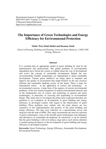
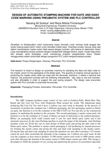
Dr. Ali AbadiChapter Eight: Optical PropertiesMaterials PropertiesElectromagnetic Radiation:Light is an electromagnetic wave or photon. In the classical sense, electromagnetic radiation isconsidered to be wave-like, consisting of electric and magnetic field components that areperpendicular to each other and also to the direction of propagation as shown in figure below.The velocity of light is c 3 x 10⁸m/scThe spectrum consists of radiation such as gamma rays, x-rays, ultraviolet, visible, infrared andradio. Visible light lies within a very narrow region of the spectrum, with wavelengths rangingbetween about 0.4µm (4x10⁻⁷ m) for violet and 0.7µm for red color.All electromagnetic radiation traverses a vacuum at the same velocity, that of light—namely, 3 x 10⁸m/s (186,000 miles/s). This velocity, c, is related to the electric permittivity of a vacuum and themagnetic permeability of a vacuum through𝑐 1𝜖0 𝜇0𝑐Energy of photon is 𝐸 ℎ𝑓 ℎ𝜈 ℎ 𝜆h: Planck’s constant 6.63x10⁻³⁴J-s1
f 𝜈 is a frequency (Hz)c is the speed of light 3x10⁸ m/s𝜆 is a wave length (m)Example: Visible light having a wavelength of 5 x10⁻⁷ m appears green. Compute the frequency andenergy of a photon of this light.We must compute the frequency of a photon of green light,ν cλ 3x10⁸m/s . 5x10 7m 6 x 10¹⁴ s-1 (Hz)The energy a photon of green lightE hc / λ (6.63x10 34J-s)(3x10⁸m/s) / 5x10 7m 3.98 x 10⁻¹⁹ J (2.48 eV)Light Interactions With Solids:When light proceeds from one medium into another (e.g., from air into a solid substance), severalthings happen. Some of the light radiation may be transmitted through the medium, some will beabsorbed, and some will be reflected at the interface between the two media. The intensity IO of thebeam incident to the surface of the solid medium must equal the sum of the intensities of thetransmitted, absorbed, and reflected beams, denoted as IT, IA, and IR respectively, orIO IT IA IRT IT /I0A IA /I0R IR /I0T 1 :T 0 OpaqueT A R 1Example: Distinguish between materials that are opaque, translucent, and transparent in terms oftheir appearance and light transmittance.Opaque materials are impervious to light transmission; it is not possible to see through them.Light is transmitted diffusely through translucent materials (there is some internal light scattering).Objects are not clearly distinguishable when viewed through a translucent material.Virtually all of the incident light is transmitted through transparent materials, and one can see clearlythrough them.2
In figure above three (3) things can happen. Light passes through easily (if the object is transparent) –Material is capable oftransmitting light with little absorption or reflection – O n e c a n s e e t h r o u g hthemLight is blurred (if the object is translucent) –Materials through which light istransmitted diffusely – L i g h t i s s c a t t e r e d w i t h i n t h e m a t e r i a l – O b j e c t s a r enot clearly visible through the materialLight is blocked (if the object is opaque) –Materials which are impervious to thetransmission of visiblelightAtomic And Electronic Interactions: The optical phenomena that occur within solid materials involve interactions between theelectromagnetic radiation and atoms, ions, and/or electrons. Two of the most important of these interactions are electronic polarization and electronenergy transitions.Electronic Polarization: One component of an electromagnetic wave is simply a rapidly fluctuating electric field.For the visible range of frequencies, this electric field interacts with the electron cloudsurrounding each atom within its path in such a way as to induce electronic polarization, or toshift the electron cloud relative to the nucleus of the atom with each change in direction ofelectric field component.Two consequences of this polarization are: (1) some of the radiation energy may be absorbed,and (2) light waves are retarded in velocity as they pass through the medium.3
Electron Transitions:The absorption and emission of electromagnetic radiation may involve electron transitions from oneenergy state to another.When a photon, or packet of light energy, is absorbed by an atom, the atom gains the energy of thephoton, and one of the atom's electrons may jump to a higher energy level. The atom is then said tobe excited. When an electron of an excited atom falls to a lower energy level, the atom may emit theelectron's excess energy in the form of a photon. The energy levels, or orbitals, of the atoms shownhere have been greatly simplified to illustrate these absorption and emission processes. For a moreaccurate depiction of electron orbitals, see Atom and Atomic Theory.Δ𝐸 ℎ𝜐Optical Properties of Metals: Metals are opaque because the incident radiation having frequencies within the visible rangeexcites electrons into unoccupied energy states above the Fermi energy, as demonstrated inFigure (a) below.Total absorption is within a very thin outer layer, usually less than 0.1 µm thus only metallicfilms thinner than 0.1 µm are capable of transmitting visible light.In fact, metals are opaque to all electromagnetic radiation on the low end of the frequencyspectrum, from radio waves, through infrared, the visible, and into about the middle of theultraviolet radiation.Metals are transparent to high-frequency (x- and γ-ray) radiation.All frequencies of visible light are absorbed by metals because of the continuously availableempty electron states, which permit electron transitions.Most of the absorbed radiation is reemitted from the surface in the form of visible light of thesame wavelength, which appears as reflected light.Aluminum and silver are two metals that exhibit this reflective behavior.Copper and gold appear red-orange and yellow, respectively, because some of the energyassociated with light photons having short wavelengths is not reemitted as visible light.4
Typical band structures:Example: Briefly explain why metals are opaque to electromagnetic radiation having photonenergies within the visible region of the spectrum.The electron band structures of metals are such that empty and available electron states are adjacentto filled states. Electron excitations from filled to empty states are possible with the absorption ofelectromagnetic radiation having frequencies within the visible spectrum. The light energy is totallyabsorbed or reflected, and, since none is transmitted, the material is opaque.5
Optical Properties of metals: All frequencies of visible light are absorbed by metals because of the continuously availableempty electron states, which permit electron transitions.Metals are opaque to all electromagnetic radiation on the low end of the frequency spectrum,from radio waves, through infrared, the visible, and into about the middle of the ultravioletradiation. Metals are transparent to high-frequency (x- and -ray) radiation.Most of the absorbed radiation is reemitted from the surface in the form of visible light of thesame wavelength, which appears as reflected light; an electron transition accompanyingreradiation.Refraction :Light that is transmitted into the interior oftransparent materials experiences decrease invelocity and as result is bent at the interface; thisphenomenon is termed refraction. The index ofrefraction n of a material is defined as the ratio ofthe velocity in vacuum c to the velocity in themedium ν , orThe magnitude of n (or the degree ofbending) will depend on the wavelength ofthe light. This effect is graphicallydemonstrated by the familiar dispersion orseparation of a beam of white light into itscomponent colors by a glass prism.6
Each color is deflected by a different amount as it passes into and out of the glass, which results in the separation ofcolors.If the angle of incidence from a normal to the surface is θ , and the angle of refraction is θ , theirrefractive index of the medium, n, is given by (provided that the incident light is coming from aphase of low refractive index such as vacuum or air) 𝑛 sin 𝜃 𝑖sin 𝜃𝑟speed of light in a material canbe related to its electrical and magneticproperties as𝜈 1𝜖𝜇where ε – electrical permittivity, and μ –magnetic permeability. Thus,𝑛 𝑐 𝜐𝜖𝜇𝜖 0 𝜇0 𝜖𝑟 𝜇𝑟Since most materials are only slightly magnetic i.e. μ 1, Thusr𝑛 𝜖𝑟Snell’s law of light refraction: refractive indices for light passing through from one medium withrefractive index n through another of refractive index n’ is related to the incident angle, θ, andrefractive angle, θ’, by𝑛sin 𝜃 ′ 𝑛′𝑠𝑖𝑛𝜃Example: Compute the velocity of light in diamond, which has a dielectric constant 𝜖𝑟 of 5.5 (atfrequencies within the visible range) and a magnetic susceptibility of -2.17 x 10⁻⁵. ε εrε0 (5.5)(8.85 x 10⁻¹² F/m) 4.87 x 10⁻¹¹ F/mμ μ0μr μ0(χm 1) (1.257 x 10⁻⁶ H/m)(1 2.17 x 10⁻⁵) 1.257 x 10⁻⁶ H/m𝜈 1𝜖𝜇 1 / {(4.87x10 11F/m)(1.257x10 6H/m)}0.5 1.28 x 10⁸m/sReflection :When light radiation passes from one medium into another having a different index of refraction,some of the light is scattered at the interface between the two media even if both are transparent. Thereflectivity R represents the fraction of the incident light that is reflected at the interface, or7
where I0 and IR are the incident and reflected beams intensities respectively. If the light isnormal (or perpendicular) to the interface, thenwhere and are the indices of refraction of the two media. If the incident light is not normal to theinterface, R will depend on the angle of incidence. When light is transmitted from a vacuum or airinto a solid s, thenExample: It is desired that the reflectivity of light at normal incidence to the surface of a transparentmedium be less than 5.0%.Which of the following materials: soda–lime glass, Pyrex glass, periclase,spinel, polystyrene, and polypropylene? Justify your selections.0.050 (ns 1)2 / (ns 1)2 (ns2 2ns 1) / (ns2 2ns 1)or, upon rearrangement 0.95ns2 2.10ns 0.95 0The value of ns is determined by using the quadratic equation solution as follows:ns ( 2.10) {( 2.10)2 (4)(0.95)(0.95)}0.5 / (2)(0.95) (2.10 0.894) / 1.90The two solutions are: ns( ) 1.576 and ns(–) 0.634.The ns( ) solution is the one that is physically reasonable. Thus, of the materials listed in tables,soda-lime glass, Pyrex glass, and polypropylene have indices of refraction less than 1.576, and wouldbe suitable for this application.Example: The index of refraction of quartz is anisotropic. Suppose that visible light is passing fromone grain to another of different crystallographic orientation and at normal incidence to the grainboundary. Calculate the reflectivity at the boundary if the indices of refraction for the two grainsare 1.544 and 1.553 in the direction of light propagation.R (n2 n1)2 / (n2 n1)2 (1.553 1.544)2 / (1.553 1.544)2 8.45 x 10⁻⁶Absorption : Nonmetallic materials may be opaque or transparent to visible light; and, if transparent theyoften appear colored. In principle, light radiation is absorbed in this group of materials bytwo basic mechanisms, which also influence the transmission characteristics of thesenonmetals.One of these is electronic polarization. Absorption by electronic polarization is importantonly at light frequencies in the vicinity of the relaxation frequency of the constituent atoms.The other mechanism involves valence band-conduction band electron transitions, whichdepend on the electron energy band structure of the material.Absorption of a photon of light may occur by the promotion or excitation of an electron fromthe nearly filled valence band, across the band gap, and into an empty state within theconduction band.8
Every nonmetallic material becomes opaque at some wavelength, which depends on themagnitude of its Eg. For example, diamond, having a band gap of 5.6 eV, is opaque toradiation having wavelengths less than about 0.22 μm.Eg (min) hc/λ(max) 1.8 eV (λ 700 nm)Eg 1.8 eV, all visible light is absorbed1.8 eV Eg 3.1 eV, ColoredEg 3.1 eV, transparent to visible light When a light beam in impinged on a material surface, portion of the incident beam that is notreflected by the material is either absorbed or transmitted through the material.Bouguer’s law: The fraction of beam that is absorbed is related to the thickness of thematerials and the manner in which the photons interact with the material’s structure.𝑰′𝑻 𝑰′𝟎 𝒆 𝜷𝒙where I’ – intensity of the beam coming out of the material,I’ – intensity of the incident beam, x – path through which the photons move, and𝜷– linear absorption coefficient in (mm-1), which is characteristic of a particular material. 0Absorption mechanisms Absorption occurs by two mechanisms: Rayleigh scattering and Compton scattering.Rayleigh scattering: where photon interacts with the electrons orbiting an atom and isdeflected without any change in photon energy. This is significant for high atomic numberatoms and low photon energies. Ex.: Blue color in the sunlight gets scattered more than othercolors in the visible spectrum and thus making sky look blue.Tyndall effect is where scattering occurs from particles much larger than the wavelength oflight. Ex.: Clouds look white.Compton scattering: interacting photon knocks out an electron loosing some of its energyduring the process. This is also significant for high atomic number atoms and low photonenergies.Photoelectric effect occurs when photon energy is consumed to release an electron fromatom nucleus. This effect arises from the fact that the potential energy barrier for electrons isfinite at the surface of the metal. Ex.: Solar cells.9
Example: Zinc selenide (ZnSe) has a band gap of 2.58 eV. Over what range of wavelengths ofvisible light is it transparent?Only photons having energies of 2.58 eV or greater are absorbed by valence-band-to-conductionband electron transitions. The minimum photon energy for visible light is 1.8 eV, which correspondsto a wavelength of 0.7 μm. λ hc / E (4.13x10 15eV-s)(3x10⁸m/s) / 2.58eV 4.80 x 10⁻⁷ m 0.48 μmThus, pure ZnSe is transparent to visible light having wavelengths between 0.48 and 0.7 μm.Example: The fraction of nonreflected radiation that is transmitted through a 5-mm thickness of atransparent material is 0.95. If the thickness is increased to 12 mm, what fraction of light will betransmitted?𝑰′𝑻 𝑰′𝟎 𝒆 𝜷𝒙 ,ln (IT' / I0') βx β ( 1 / x) ln IT' / I0' (15mm) ln(0.95) 1.026 x 10⁻² mm-1And computation of IT'/I0' when x 12 mm , IT' / I0' exp ( βx) exp[ (1.026x10 2mm 1)(12mm)] 0.884Transmission :The phenomena of absorption, reflection, and transmission may be applied to thepassage of light through a transparent solid.For an incident beam of intensity I0 that impinges on the front surface of a specimen of thickness land absorption coefficient ß the transmitted intensity at the back face IT is where R is the reflectance.Transparent materials appear colored as a consequence of specific wavelength ranges of light that areselectively absorbed; the color discerned is a result of the combination of wavelengths that aretransmitted.10
If absorption is uniform for all visible wavelengths, the material appears colorless; examples includehigh-purity inorganic glasses and high-purity and single-crystal diamonds and sapphire.Usually, any selective absorption is by electron excitationthe fraction of the visible light having energies greater than Eg (1.8 to 3.1 eV) is selectivelyabsorbed by valence band–conduction band electron transitions.Of course, some of this absorbed radiation is reemitted as the excited electrons drop back into theiroriginal, lower-lying energy states. It is not necessary that this reemission occur at the samefrequency as that of the absorption. As a result, the color depends on the frequency distribution ofboth transmitted and reemitted light beams.Example: The transmissivity T of a transparent material 15 mm thick to normally incident light is0.80. If the index of refraction of this material is 1.5, compute the thickness of material that will yielda transmissivity of 0.70. All reflection losses should be considered.R (ns 1)2 / (ns 1)2 (1.5 1)2 / (1.5 1)2 4.0 x 10⁻²since: 𝐼𝑇 𝐼0 1 𝑅 2 𝑒 𝛽𝑙IT / I0(1 R)2 e-βlAnd taking the natural logarithms of both sides of this expression givesln[IT / I0(1 R)2] βlβ 1 / l ln [IT / I0(1 R)2]Since the transmissivity is T is equal to IT/I0, then the above equation takes the formβ (1/ l) ln [T / (1 R)2]β (1 / 15mm) ln [0.80 / (1 4.0x10 2)2] 9.43 x 10⁻³ mm-1Colors: Color determined by sum of frequencies of, transmitted light, and -re-emitted light from electrontransitions. Small differences in composition can lead to large differences in appearance Ex: Cadmium Sulfide (CdS)--Egap 2.4eV,--absorbs higher energy visible light (blue,violet),--Red/yellow/orange is transmitted and gives it color. For example, high-purity single-crystal Al2O3(sapphire) is colourless If only 0.5 - 2.0% of Cr2O3 add, the material looks red(ruby) The Cr substitutes for the Al and introduces impurity levels in the bandgap of the sapphire These levels give strong absorptions at: 400nm (green) and 600nm (blue)leaving only red to be transmitted.A similar technique is used to color glasses or pottery glaze by adding impurities into the moltenstate:Cu2 : blue-green, Cr3 : greenCo2 : blue-violet, Mn2 : yellow11
If Egap 1.8eV, full absorption; color is black (Si, GaAs) If Egap 3.1eV, no absorption; colorless (diamond) If Egap in between, partial absorption; material has a color. reflection and absorption are dependent on wavelength and transmission is what’s left over!Thus the three components for a green glass are:Example: Briefly explain why some transparent materials appear colored while others are colorless.For a transparent material that appears colorless, any absorption within its interior is the same for allvisible wavelengths. On the other hand, if there is any selective absorption of visible light (usually byelectron excitations), the material will appear colored, its color being dependent on the frequencydistribution of the transmitted light beam.Example: Briefly explain what determines the characteristic color of (a) a metal and (b) atransparent nonmetal.(a) The characteristic color of a metal is determined by the distribution of wavelengths of thenonabsorbed light radiation that is reflected.(b) The characteristic color of a transparent nonmetal is determined by the distribution ofwavelengths of the nonabsorbed light radiation that is transmitted through the material.Translucency: Even after the light has entered the material, it might yet be reflected out again due toscattering inside the material. Even the transmitted light can lose information by being scattered internally. So a beam oflight will spread out or an image will become blurred. In extreme cases, the material could become opaque due to excessive internal scattering. Scattering can come from obvious causes: grain boundaries in poly-crystalline materials fine pores in ceramics different phases of materials In highly pure materials, scattering still occurs and an important contribution comes fromRayleigh scattering This is due to small, random differences in refractive index from place to place. In amorphous materials such as glass this is typically due to density or compositionaldifferences in the random structure.12
In crystals, lattice defects, thermal motion of atoms etc. also give rise to Rayleigh scattering.Rayleigh scattering also causes the sky to be blue. The reason for this is the wavelengthdependence of Rayleigh scattering: scattering goes as λ-4. so since λ red 2 λ blue light is scattered 16 times more than red lightThis mechanism is of great technological importance because it governs losses in opticalfibers for communication.But before we get onto fibers, we will mention a couple more basic effectsFigure: Rayleigh scattering involves the polarization of a small dielectric particle or a region that is much smaller thanthe light wavelength. The field forces dipole oscillations in the particle (by polarizing it) which leads to the emission ofEM waves in "many" directions so that a portion of the light energy is directed away from the incident beam.Figure : Photograph showing the lighttransmittance of three aluminum oxidespecimens. From left to right; singlecrystal material (sapphire), which istransparent; a polycrystalline and fullydense (nonporous) material, which istranslucent; and a polycrystalline materialthat contains approximately 5% porosity,which is opaque.Optical applications: Light interacts with a material in many ways. Depending on the material, its crystal-/micro-structure, and also on the characteristics of incidentlight, there are many phenomena occurs, which are known as optical phenomena. These include:o luminescenceo laserso thermal emissiono photo-conductivityo optical fibers All these find quite many applications in technology for everyday life13
Luminescence It is the process where a material absorbs energy and then immediately emits visible or near-visibleradiation. It consists of electron excitation and then dropping down to lower energy states. Visiblelight is emitted when it falls back to a lower energy state if 1.8 eV ℎ𝜐 3.1 eV.-8 If the reemission of radiation occurs within 10 sec after excitation, the luminescence is called-8fluorescence, and if it takes longer than 10 sec, it is known as phosphorescence. Special materials called phosphors have the capability of absorbing high-energy radiation andspontaneously emitting lower-energy radiation. Ex.: some sulfides, oxides, tungstates, and feworganic materials. Ordinarily, pure materials do not display these phenomena, and to induce them,impurities in controlled concentrations must be added. The intensity of luminescence is given as: 𝐼 𝐼0 exp 𝑡𝜏 where I – initial intensity of luminescence,0 I – fraction of luminescence after time, t, τ - relaxation time, constant for a material. Luminescence process is classified based on the energy source for electron excitation as photoluminescence, cathode-luminescence, and electro-luminescence.Photo-luminescence Photo-luminescence occurs in fluorescent lamps. Arc between electrodes excites mercury in lampto higher energy level. Electron falls back emitting UV light . Fluorescent lamps consist of a glasshousing, coated on the inside with specially prepared tungstates or silicates. Ultraviolet light isgenerated within the tube from a mercury glow discharge, which causes the coating to fluoresce andemit white light. Here ultra-violet radiation from low-pressure mercury arc is converted to visible light by calciumhalo-phosphate phosphor (Ca F P O ).10 2 624-- In commercial lamps, about 20% of F ions are replaced with Cl ions.3 2 Antimony, Sb , ions provide a blue emission while manganese, Mn , ions provide an orange-redemission band.Cathode-luminescence: Cathode-luminescence is produced by an energized cathode which generates a beam of highenergy bombarding electrons. Applications of this include electron microscope; cathode-ray oscilloscope; color televisionscreens. The modern televisions have very narrow, about 0.25 mm wide, vertical stripes of red-, green-, andblue- emitting phosphors deposited on the inner surface of the screens. Commercial phosphors for different colors are: red – yttrium oxy-sulfide (Y O S) with 3% 3 22europium (Eu); green – (Zn,Cd)S with a Cu acceptor and Al donor; blue – zinc sulfide (ZnS) -with Ag acceptor and Cl donor.14
Electro-luminescence: Electro-luminescence occurs in devices with p-n rectifying junctions which are stimulated by anexternally applied voltage. When a forward biased voltage is applied across the device, electrons and holes recombine at thejunction and emit photons in the visible range (mono-chromatic light i.e. singe color). Thesediodes are called light emitting diodes (LEDs). LEDs emit light of many colors, from red to violet, depending on the composition of thesemiconductor material used. Ex.: GaAs, GaP, GaAlAs, and GaAsP are typical materials for LEDs. Materials for colored LEDs areWave length 0.35Lasers : Laser is an acronym for light amplification bystimulated emission of radiation. It is in fact specialapplication of luminescence. Unlike most radiation processes, such as luminescence,which produce incoherent light, the light produced bylaser emission is coherent. All of the light emission we have mentioned so far isspontaneous. It happened just due to randomlyoccurring ―natural‖ effects Stimulated emission refers to electron transitions that are ―encouraged‖ by the presence of otherphotons Einstein showed that an incident photon with E Eg was equally likely to cause stimulatedemission of light as to be absorbed The emitted light has the same energy and phase as the incident light ( coherent)15
Under normal circumstances, there are few excited electrons and many in the ground-state,so we get predominantly absorption. If we could arrange for more excited than non-excited electrons, then we would get mostlystimulated emission. This is based on the fact that in certain materials, electrons excited by a stimulus produce photonswhich in turn excite additional photons of identical wavelength. Thus a large amplification of thephotons emitted in the material occurs, as shown in figure below. Lasers are useful in many applications such as welding, metal cutting, heat treatment, surgery,mapping, reading compact disks, etc. Ex.: Ruby, single crystal of Al O doped with little amount23of Cr O ; yttrium aluminium garnet (Y Al O – YAG) doped with neodymium, Nd; CO gas;2335122He-Ne gas; some semi-conductors like GaAs and InGaAsP.Presented in this figure is an illustration of thegain, or amplification, that occurs withincreased path length in the resonant cavitydue to the mirrors at each end. Figure (a)shows the beginning of stimulatedemission, which is amplified in figure (b)through Figure (g) as the light is reflectedfrom the mirrors positioned at the cavityends. A portion of light passes through thepartially reflected mirror on the right-handside of the cavity (figures (b,d, and f))during each pass. Finally, at the equilibriumstate (figure (h)), the cavity is saturatedwith stimulated emission.16
Thermal emission When a material is heated, electrons are excited tohigher energy levels, particularly in the outerenergy levels where the electrons are lessstrongly bound to the nucleus. These excited electrons, upon dropping back to theground state, release photons in process what iscalled thermal emission. During thermal emission a continuous spectrum ofradiation is emitted with a minimum wavelengthand the intensity distribution is dependent on thetemperature as shown in figure beside. Higher the temperature, wider will be the range ofwavelengths emitted. By measuring the intensityof a narrow band of the emitted wavelengthswith a pyrometer, material’s temperature can be estimated.Photo-conductivity The conductivity of semiconducting materials depends on the number of free electrons in theconduction band and also the number of holes in the valence band Bombardment of semiconductors by photons, with energy equal to greater than the band gap, mayresult in creation of electron-hole pairs that can be used to generate current. This process is calledphoto-conductivity. It is different from photo-electric effect in the sense that an electron-hole pair is generated whose energyis related to the band gap energy instead of free electron alone whose energy is related to the Fermilevel. The current produced in photo-conductivity is directly related to the incident light intensity. This phenomenon is utilized in photographic light meters. Cadmium sulfide (CdS) is commonly usedfor the detection of visible light, as in light meters. Photo-conductivity is also the underlying principle of the photo-voltaic cell, known to common man assolar cell, used for conversion of solar energy (sunlight) into electricity.17
Optical fibers : Optical fibers have revolutionized the communication industry. These systems consists of transmitter (a semiconductor laser) toconvert electrical signals to light signals, optical fiber totransmit the light signals, and a photodiode to convert lightsignals back to electrical signals. It primarily consists of core, cladding and coating. The coretransmits the signals, while the cladding constrains the lightbeam to the core; outer coating protects the core and claddingfrom the external environment. Typically both the core and cladding are made of special typesof glass with carefully controlled indices of refraction. The indices of refraction are selected such that𝑛𝑐𝑙𝑎𝑑𝑑𝑖𝑛𝑑 𝑛𝑐𝑜𝑟 Once the light enters the core from the source, it is reflectedinternally and propagates along the length of the fiber. Internal reflection is accomplished by varying the index ofrefraction of the core and cladding glass materials. Usuallytwo designs are employed in this regard.Types of optical fibers In step-index optical fiber, there is a sharp change in refractiveindex between the core and cladding. In this design outputpulse will be broader than the input one. It is because light raystraveling in different trajectories have a variety of path lengths. It is possible to avoid pulse broadening by using graded-indexfiber. This results in a helical path for the light rays, as opposed to zig-zag path in a step-index fiber. Here impurities such as boron oxide (B O ) or germanium dioxide (GeO ) are added to the silica glass232such that the index of refraction varied gradually in parabolic manner across the cross section. Thisenables light to travel faster while close to the periphery than at the center. This
Dr. Ali Abadi Chapter Eight: Optical Properties Materials Properties Electromagnetic Radiation: Light is an electromagnetic wave or photon. In the classical sense, electromagnetic radiation is considered to be wave-like, cons