Transcription
INSTALLATIONGUIDEElementFor help, call 1-877-BIG-FANSor visit www.bigassfans.com
ELEMENT BY BIG ASS FANS Installation ChecklistDid a structural engineer approve the mounting structure? (See p. 6 for Big Ass Fans approvedmounting structures.)Are you familiar with the function and use of the safety cables? (See pp. 14–15 for information onproperly securing the safety cables.)Will the fan be installed so that the blades are at least 10 ft (3.05 m) above the floor?Will the fan be installed so that the blades have at least 2 ft (0.61 m) of clearance fromobstructions?Will the fan be installed so that it is not subjected to high winds, such as from an HVAC system?Install the fan so that it is 1x fan diameter away from a diffuser if the fan is at same level or abovediffuser. If the fan is below a diffuser, install the fan so that it is 2x fan diameter from the diffuser.Will the distance between multiple fans be at least 2.5x the fans’ diameter when measured fromthe centers of the fans?If installing to an I-beam, is the upper yoke the correct size? (See p. 7 for more information oninstalling the fan to an I-beam.)If you ordered multiple fans, did you keep the parts for each fan together?Customer Service: 1-877-BIG-FANS(International: 1 859 233 1271)WWW.BIGASSFANS.COM 2011 DELTA T CORP.ALL RIGHTS RESERVED
ElementInstallation GuideInstallation Guide:Apr. 2015Rev. LThis product was manufactured in a plant whose ManagementSystem is certified as being in conformity with ISO 9001:2008.Conforms to ANSI/UL STD 507: Electric FansCertified to CAN/CSA C22.2 No.113: Fans & VentilatorsContact InformationManufacturing2425 Merchant StreetLexington, KY 405111-877-BIG-FANSwww.bigassfans.comCustomer Service2348 Innovation DriveLexington, KY 405111-877-BIG-FANSIntl.: 1 859 233 1271www.bigassfans.comWarranty Returns800 Winchester RoadLexington, KY 405051-877-BIG-FANSwww.bigassfans.comAustralia OfficeUnit 22, 1029 Manly RoadTingalpa QLD 4173, Australia(07) 3292 0100www.bigassfans.com/auElement and the Element logo are trademarks of Delta T Corporation, registered in the United States and/or other countries. All other trademarks used herein are the properties of theirrespective owners. No part of this document may be reproduced or translated into a different language without the prior written consent of Big Ass Fan Company. The information containedin this document is subject to change without notice. For the most up-to-date information, see the online Element Installation Guide at www.bigassfans.com.www.bigasssolutions.com/patents
ELEMENT BY BIG ASS FANS iiIMPORTANT SAFETY INSTRUCTIONSREAD AND SAVE THESE INSTRUCTIONSWARNING—TO REDUCE THE RISK OF FIRE, ELECTRIC SHOCK, OR INJURY TO PERSONS, OBSERVE THE FOLLOWING:a. Installation work and electrical wiring must be done by qualified person(s) in accordance with all applicable codes.b. When cutting or drilling into wall or ceiling, do not damage electrical wiring and other hidden utilities.CAUTION: The installation of a Big Ass Fan must be in accordance with the requirements specified in this installation manualand with any additional requirements set forth by the national electric code (NEC), ANSI/NFPA 70-2011, and all local codes.Code compliance is ultimately YOUR responsibility!WARNING: The fan controllers contain high voltage capacitors which take time to discharge after removal of mains supply.Before working on the fan controller, ensure isolation of mains supply from line inputs at the fan controller board (L1, L2/N).Wait three minutes for capacitors to discharge to safe voltage levels. Failure to do so may result in personal injury or death.CAUTION: Exercise caution and common sense when powering the fan. Do not connect the fan to a damaged or hazardouspower source. Do not attempt to resolve electrical malfunctions or failures on your own. Contact Big Ass Fans if you have anyquestions regarding the electrical installation of this fan.Suitable for use with solid-state speed controls.WARNING—To reduce the risk of fire, electric shock, and injury to persons, Big Ass Fans must be installed with Big AssFan supplied controllers that are marked (on their cartons) to indicate the suitability with this model. Other parts cannot besubstituted.CAUTION: When service or replacement of a component in the fan requires the removal or disconnection of a safety device,the safety device is to be reinstalled or remounted as previously installed.WARNING: Risk of fire, electric shock, or injury to persons during cleaning and user-maintenance! Disconnect the appliancefrom the power supply before servicing.WARNING—TO REDUCE THE RISK OF FIRE, ELECTRIC SHOCK, OR INJURY TO PERSONS, OBSERVE THE FOLLOWING:a. Use this unit only in the manner intended by the manufacturer. If you have questions, contact the manufacturer.b. Before servicing or cleaning unit, switch power off at service panel and lock the service disconnecting means to preventpower from being switched on accidentally. When the service disconnecting means cannot be locked, securely fasten aprominent warning device, such as a tag, to the service panel.CAUTION: Do not bend the airfoils when installing or servicing the fan. Do not insert foreign objects between rotating airfoils.WARNING: Stay alert, watch what you are doing, and use common sense when installing fans. Do not install fans if tiredor under the influence of drugs, alcohol, or medication. A moment of inattention while installing fans may result in seriouspersonal injury.CAUTION: The installation of this fan requires the use of some power tools. Follow the safety procedures found in the owner’smanual for each of these tools and do not use them for purposes other than those intended by the manufacturer.CAUTION: The Big Ass Fans product warranty will not cover equipment damage or failure that is caused by improperinstallation.CAUTION: Do NOT install the fan where it may come into direct contact with water unless the fan is labeled, “Suitable for usein wet locations.”WWW.BIGASSFANS.COM 2011 DELTA T CORP.ALL RIGHTS RESERVED
ELEMENT BY BIG ASS FANS ContentsGeneral InformationImportant Safety Information Regulatory Compliance Information iiiiIntroductionThank You About Big Ass Fans About This Fan 111Pre-InstallationWhat’s in the Box Parts Included Tools Needed Important Weights Fan Diagram Preparing the Work Site 234456Mounting Structure:I-BeamAttach Upper Yoke (to I-Beam) 7Mounting Structure:Bar Joists1. Select Proper Angle Irons 2. Pre-drill Angle Irons 3. Secure Angle Irons (if span is longer than 8 ft) 4a. Fasten Single Angle Irons to Roof Structure Mounting Points 4b. Fasten Double Angle Irons to Roof Structure Mounting Points 5. Attach Upper Yoke (to Angle Irons) 899101112Hanging the Fan1. Attach Extension Tube (to Upper Yoke) 2. Install Trim Accessory 3. Secure Upper Safety Cable 4. Attach Main Fan Unit (to Extension Tube) 5. Secure Lower Safety Cable 1313141515Installing Airfoils1. Attach Winglets to Airfoils 2. Position Airfoils and Trim 3. Attach Airfoils to Main Fan Unit 161616Installing Dome1. Assemble Dome 2. Attach Dome to Static Hub 3. Attach Center Cap to Dome 171717Installing Guy Wires1. Attach Guy Wire Brackets 2. Attach Locking Carabiners to Guy Wire Brackets 3. Attach Beam Clamp 4. Route Guy Wire through Gripple 5. Install Remaining Guy Wires 1818181919Electrical InstallationElectrical Installation Safety Mounting the Wall Controller Wiring Connections Delta Secondary Wiring Connections Diagram Attach Wiring Access Door Daisy Chaining Addressing 2020212122222324Interfacing withBuilding AutomationSystemsWiring 0–10 VDC Analog Speed Reference 4–20 mA Analog Speed Reference 252627WWW.BIGASSFANS.COM 2011 DELTA T CORP.ALL RIGHTS RESERVED
ELEMENT BY BIG ASS FANS Operating the FanNavigating the Controller Menu Speed Selection Screen Active Fan Selection Screen Toggling Fan Direction Toggling the Auxiliary Relays 2830313233Preventive MaintenanceAnnual Preventive Maintenance General Preventative Maintenance Annual Maintenance Checklist 343435TroubleshootingGeneral Troubleshooting Troubleshooting Fault Screens 3738Warranty ReturnInstructionsAcknowledgment & Return Instructions Warranty Claim Form Instructions Warranty Claim Form Responsibility Agreement 39404142Big Ass Fan CertifiedInstallersCheck-In Procedure Close-Out Procedure 4345WWW.BIGASSFANS.COM 2011 DELTA T CORP.ALL RIGHTS RESERVED
ELEMENT BY BIG ASS FANS Introduction1Thank you and congratulations on your purchase of a Big Ass Fan, an efficient and cost-effective way to stay cool in the summer andwarm in the winter. The revolutionary design of our fans combines the best of both form and function to bring power performanceand a sleek look to any setting. More importantly, you have purchased a product that is backed by extensive research, thoroughtesting, and quality manufacturing. We’re ready to answer any questions or comments at 1-877-BIG-FANS or visit our Web site atwww.bigassfans.com.Who we are and what we doBig Ass Fans has been the preeminent manufacturer of large-diameter, low-speed fans since 1999. With a worldwide presence andlocated in beautiful Lexington, KY, we research, design, and manufacture the most effective air movement solutions on the market.Our never-ending commitment to quality and innovation keeps us at the leading edge of a burgeoning industry. With an eye to helpingcustomers satisfy their needs, and a strong sense of corporate responsibility to the community, Big Ass Fans has redefined the waybusiness is done.About this fanTechnical specificationsFandiameterInput powerMaximum ampMaximumRPMFan weight*12 ft (3.7 m)10 A @ 100–250 V, 1 Φ6.4 A @ 100–125 V, 1 Φ3.2 A @ 200–250 V, 1 Φ82230 lb (104 kg)14 ft (4.3 m)10 A @ 100–250 V, 1 Φ6.4 A @ 100–125 V, 1 Φ3.2 A @ 200–250 V, 1 Φ64244 lb (111 kg)16 ft (4.9 m)10 A @ 100–250 V, 1 Φ6.4 A @ 100–125 V, 1 Φ3.2 A @ 200–250 V, 1 Φ52258 lb (117 kg)18 ft (5.5 m)10 A @ 100–250 V, 1 Φ6.4 A @ 100–125 V, 1 Φ3.2 A @ 200–250 V, 1 Φ43272 lb (123 kg)20 ft (6.1 m)10 A @ 100–250 V, 1 Φ6.4 A @ 100–125 V, 1 Φ3.2 A @ 200–250 V, 1 Φ33286 lb (130 kg)* Fan weight includes 3-ft extension tube and upper yoke.WWW.BIGASSFANS.COM 2011 DELTA T CORP.ALL RIGHTS RESERVED
ELEMENT BY BIG ASS FANS 2Pre-InstallationWhat’s in the boxCAUTION: Do not remove the motor from its protective packaging prior to hanging it!CAUTION: To prevent damage, avoid contact with the printed circuit board located on the bottom of the fan!CAUTION: If you ordered multiple fans, be sure to keep the components of each fan together.The fan is shipped in three boxes. The largest box contains the main fan unit assembly, upper yoke, beam clips & spacers, dome,dome clips, dome retainer, dome washer, center cap, airfoil trim, winglets, wall control, wall control mounting plate, test cable, mountinghardware, and fire relay. The fire relay and its Installation Guide (not shown below) are packaged in a small box within the main box.A smaller box contains the airfoils, airfoil retainers, and airfoil hardware. Another small box contains the extension tube with attachedsafety cable. If you are missing any piece required for installation, contact Big Ass Fans.Note: Dashed lines indicate internal boxes. Drawings below are not to scale.Main BoxWall Controller(10) WingletWall ControllerMounting PlateMain Fan Unit(4) Dome ClipTest Cable(10) Airfoil TrimCenter CapDome RetainerTrim Accessory (21) 1/2” Nut Cover(2) Beam Clip& (2) SpacerUpper YokeDome WasherMountingHardwareDome1Dome RetainerHardwareExtensionTube BoxAirfoil BoxAirfoilHardware(10) Airfoil(10) AirfoilRetainer1. Round dome shown. An optional flat dome is available.WWW.BIGASSFANS.COM 2011 DELTA T CORP.ALL RIGHTS RESERVEDExtension Tube
ELEMENT BY BIG ASS FANS 3Pre-Installation (cont.)Parts includedCAUTION: The components located on the bottom of the main fan unit are fragile and include sensitive electronics. Do notremove the assembly from its protective packaging prior to hanging it from the extension tube!Note: A fire relay is also included with the fan (not shown below). Drawings below are not to scale.HardwareBeam Clip Hardware(4) 1/2-13 x 2” Bolt(8) 1/2” Flat Washer(4) 1/2-13 Nylock NutExtension Tube Hardware(2) 1/2-13 x 6” Bolt(4) 1/2” Flat Washer(2) 1/2-13 Nylock NutMain Fan Unit Hardware(2) 1/2-13 x 5” Bolt(4) 1/2” Flat Washer(2) 1/2-13 Nylock NutLower Safety Cable Hardware(1) 1/2-13 x 1 1/2” Bolt(1) 1/2” Flat WasherAccess Door Hardware1(2) 8-32 x 1/2” ScrewWinglet Hardware(10) 1/4-20 x 3/4” ScrewAirfoil Hardware(20) 5/16-18 x 1-3/4” GR 8 Bolt(40) 5/16” Washer(20) 5/16-18 Nylock NutDome Retainer Hardware2(4) 8-18 x 3/8” Screw(4) 1/4-20 x 5/8” ScrewGuy Wire Hardware3(8) Locking Carabiner(4) 1/4” Beam Clamp(4) 1/4-20 x 1” Eyebolt(4) 1/4-20 Hex Nut(4) Gripple (4) Guy Wire(8) Wire Rope ClipMountingAirfoils(2) Beam Clip &(2) SpacerUpper YokeExtension Tube &Safety Cable1Main Fan Unit4(10) Airfoil(10) Winglet(10) AirfoilTrim(10) AirfoilRetainer(21) NutCover1. The Access Door Hardware is installed in the extension tube when the fan is shipped. The shackle for the safety cable is included with the Mounting Hardware.2. The Dome Retainer Hardware is packed in the dome retainer box. Big Ass Fans does not recommend installing a light module.3. Guy wires are designed to constrain fan’s lateral movement and are only included in some fan packages. Big Ass Fans recommends using guy wires if the if the fan’sextension tube is 4 ft or longer, if the fan is exposed to high winds or similar conditions, or if the fan is close to any building fixtures. Guy Wire Hardware is baggedseparately from hardware boards.4. The components located on the bottom of the main fan unit are fragile and include sensitive electronics. Do not remove the assembly from its protective packaging prior tohanging it from the extension tube!WWW.BIGASSFANS.COM 2011 DELTA T CORP.ALL RIGHTS RESERVED
ELEMENT BY BIG ASS FANS 4Pre-Installation (cont.)Parts included (cont.)Wall ControllerDome1(4) imAccessoryWall ControllerWall ControllerMounting Plate1. The Dome Retainer Hardware is packed in the dome retainer box. Big Ass Fans does not recommend installing a light module.2. Round dome shown. An optional flat dome is available.Tools neededBig Ass Fans recommends gathering the following tools prior to beginning installation. Note: This list of suggested tools is notexhaustive. Additional tools may be necessary.Mechanical Installation:Electrical Installation:Standard Wrench SetPhillips and Flat Head ScrewdriversStandard Socket and Ratchet SetPair of #10 to #14AWG StrippersTorque Wrench capable of 40 ft·lb (54.2 N·m)Pair of Medium Size Channel LocksPhillips and Flat Head ScrewdriversMultimeterStandard Allen Wrench SetCAT5/5E CrimperCAT5/5E Cable testerImportant weightsPartWeightUpper Yoke17 lbs (7.7 kg)Extension Tube (3’)15 lbs (9.1 kg)Motor Assembly127 lbs (57.6 kg)Airfoil (10)7 lbs (3.1 kg) eachWinglet (10)0.8 lbs (0.4 kg) eachAluminum Dome2.2 lbs (1.0 kg)Wall Controller0.4 lbs (0.2 kg)WWW.BIGASSFANS.COM 2011 DELTA T CORP.ALL RIGHTS RESERVED
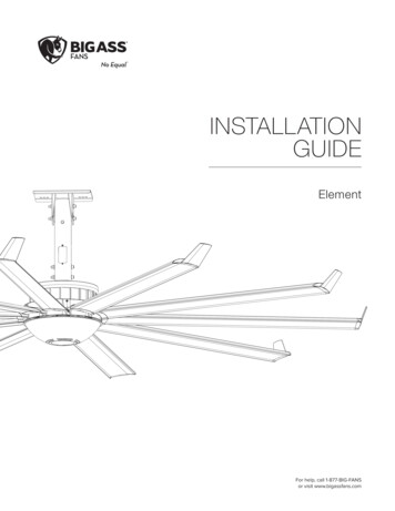
ELEMENT BY BIG ASS FANS Pre-Installation (cont.)Fan diagram5A. Upper Yoke: Secures fan to mounting structure.B. Upper Safety Cable: Redundant safety feature that secures fan tomounting structure in the event of an accident.C. Extension Tube: Extends fan from ceiling and provides path for wiring.D. Access Door: Provides access to lower safety cable.E. Main Fan Unit: Includes direct drive motor, onboard controls, and hub(see p. 1 for more information).F. Airfoil: Provides air movement. In the event of a collision, safety retainerssecure the airfoils to the fan hub.G. Winglet: Improves the efficiency of the fan by reducing drag.H. Dome: Aluminum enclosure for components on underside of fan. Note:Round dome shown. An optional flat dome is available.WWW.BIGASSFANS.COM 2011 DELTA T CORP.ALL RIGHTS RESERVED
ELEMENT BY BIG ASS FANS 6Pre-Installation (cont.)Preparing the work siteCAUTION: Mount fan only to an angle iron or I-beam.When surveying the work site keep the following guidelines in mind: Element weighs, at maximum, 286 lbs (with 3-ft extension tube). A scissor lift or other suitable means for lifting the weight of the fanand at least two installation personnel will be required. Big Ass Fans can only be hung from an angle iron or an I-beam. The minimum dimensions of the angle iron must be 2-1/2’’ 2-1/2” 1/4” (6.4 cm 6.4 cm 0.6 cm) and it cannot be longer than 6 ft (1.8 m). It must be secured to structure. Do not mount the fan tosingle purlins, trusses, or bar joists. Consult a structural engineer for installation methods not covered in the manual.I-BeamAngle Iron Fan installation area must be free of obstructions such as lights, cables, sprinklers, or other building structure. The airfoils shouldhave at least 2 ft (0.61 m) of clearance from any obstructions. Adhere to the safety requirements in the table below when selecting the fan location.Safety requirementMinimum distancesClearance 2 ft from all fan parts. The fan installation area must be free of obstructions such as lights, cables,sprinklers, or other building structure.Blade height 10 ft above the floorHVAC equipment 1x fan diameter if at same level or above diffuser. 2x fan diameter if below diffuser.Fan spacing2.5x fan diameter, center-to-centerRadiant/IR heatersSee the manufacturer’s requirements for the minimum clearance to combustibles. Fans mounted on lightweight I-beams (common in steel buildings) could cause the beam to flex and the fan to move significantlyduring operation. If this flexing causes a clearance problem, we suggest installing a stiffening strut on a nearby beam. The fan should be visible from the location of the wall controller. The mounting system must be able to withstand the torque forces generated by the fan. A 20-ft diameter fan generates nearly 300ft·lb (406.7 N·m) of torque during operation. If the fan is to be located near infrared or radiant heaters, Big Ass Fans recommends that the fan be mounted according to thefollowing guidelines:–– The fan should be mounted outside of the clearances recommended by the manufacturer of the heater and at a height equal to orabove the shielding on the heating element.–– The controller must be mounted on the opposite side of the heater.–– If mounting the fan below the heater shielding, all fan elements must be located outside of the clearances recommended by themanufacturer of the heater and the controller must be remotely mounted. Ensure the mounting location will not expose the fan to direct contact with water unless the fan is labeled, “Suitable for use in wetlocations.”WWW.BIGASSFANS.COM 2011 DELTA T CORP.ALL RIGHTS RESERVED
ELEMENT BY BIG ASS FANS Mounting Structure: I-Beam7Big Ass Fans should only be hung from an I-beam or bar joists. See the following page for bar joist mountinginstructions. Consult a structural engineer for installation methods not covered in this manual.WARNING: The fan should not be installed unless the structure on which the fan is to be mounted is of soundconstruction, undamaged, and capable of supporting the loads of the fan and the method of attachment to the structure.A structural engineer should verify that the structure is adequate prior to fan installation. Verifying the stability of themounting structure is the sole responsibility of the customer and/or end user, and Big Ass Fans hereby expresslydisclaims any liability arising therefrom, or arising from the use of any materials or hardware other than those supplied byBig Ass Fans or otherwise specified in these installation instructions.CAUTION: It is not recommended to mount a Big Ass Fan from a fabricated I-beam.CAUTION: Install the spacers only if the thickness of the I-beam flange exceeds 3/8” (1cm). The mounting holes on thespacer are closer to one side than the other. Make sure this side is facing the I-beam.CAUTION: Ensure the mounting location will not expose the fan to direct contact with water unless the fan is labeled,“Suitable for use in wet locations.”1. Attach upper yoke (to I-beam)Measure the flange width of the I-beam from which the fan will be hung. Consult the tables and diagram below to determine what sizeupper yoke is included with your fan package. Select the upper yoke mounting holes that match the flange width of the I-beam.Secure the upper yoke to the I-beam with the Beam Clip Hardware as shown. Tighten the bolts to 40 ft·lb (54.2 N·m) using a torquewrench and 3/4” socket.Proceed to “Hanging the Fan” (p. 13).Beam Clip Hardware (BAF-Supplied):a. (4) 1/2-13 x 2” GR 8 Boltb. (8) 1/2’’ Flat Washerc. (4) 1/2-13 Nylock Nutd. (2) Beam Clipe. (2) SpacerSmall Upper Yoke13-3/4’’ (349 mm) x 10” (258 mm)I-beamflange widthUpper yokemounting holes5” (127 mm) to6-5/8” (168 mm)Inner holes 6-5/8” (168 mm) to8-1/4” (210 mm)Middle holes 8-1/4”(210 mm) to9-7/8”(250 mm)Outer holesouter holesmiddle holesinner holesUpper Yoke(top view)Large Upper Yoke18-1/2’’ (470 mm) x 10” (258 mm)I-beamflange widthUpper yokemounting holes9-7/8” (250 mm) to11-3/8” (289 mm)Inner holes 11-3/8” (289 mm) to13” (330 mm)Middle holes 13” (330 mm) to14-5/8” (371 mm)Outer holesSide ViewabdebcWWW.BIGASSFANS.COM 2011 DELTA T CORP.ALL RIGHTS RESERVED
ELEMENT BY BIG ASS FANS 8Mounting Structure: Bar JoistsIf you are installing the fan to an I-beam and have attached the upper yoke, proceed to “Hanging the Fan” (p. 13).WARNING: The fan should not be installed unless the structure on which the fan is to be mounted is of soundconstruction, undamaged, and capable of supporting the loads of the fan and the method of attachment to the structure.A structural engineer should verify that the structure is adequate prior to fan installation. Verifying the stability of themounting structure is the sole responsibility of the customer and/or end user, and Big Ass Fans hereby expresslydisclaims any liability arising therefrom, or arising from the use of any materials or hardware other than those supplied byBig Ass Fans or otherwise specified in these installation instructions.WARNING: Never use beam clamps when mounting the fan to angle irons! Beam clamps are only intended for I-beaminstallations.CAUTION: Do not install the fan from a single purlin, truss, or bar joist.CAUTION: Unsupported angle iron spans should not exceed 12 ft (3.7 m).CAUTION: The angle irons must be fastened to the roof structure at each end.CAUTION: Ensure the mounting location will not expose the fan to direct contact with water unless the fan is labeled,“Suitable for use in wet locations.”1. Select proper angle ironsNote: Angle irons and angle iron hardware are not included with the fan.Follow the table below when selecting angle irons for fan installation.Angle iron span(between mounting points)Minimum angle iron dimensions(W x H x T)Number of angleirons needed6’ (1.8 m) or less2.5” (6.4 cm) x 2.5” (6.4 cm) x 0.25” (0.6 cm)2over 6’ (1.8 m) to 8’ (2.4 m)3” (7.6cm) x 3” (7.6 cm) x 0.25” (0.6 cm)2over 8’ (2.4 m) to 12’ (3.7 m)3” (7.6 cm) x 3” (7.6 cm) x 0.25” (0.6 cm)411. Two pairs of angle irons. Pairs should be placed back to back and fastened in center (see step 3).8m)6’ (1.overoverWWW.BIGASSFANS.COMssor le’ (2.4–8.8m)6’ (148’ (2.m)’ (3.712m) – 2011 DELTA T CORP.m)ALL RIGHTS RESERVEDAngle Iron Side View(see table for dimensions)HeightThicknessWidth
ELEMENT BY BIG ASS FANS 9Mounting Structure: Bar Joists (cont.)2. Pre-drill angle ironsDrill two Ø 9/16” (1.4 cm) holes exactly 5-3/8” (13.7 cm) apart in the centers of two angle irons.Measure the distance between the mounting points of the roof structure that the angle irons will span. Measure the same distance onthe angle irons and drill Ø 9/16” (1.4 cm) holes through each end of the angle irons. Drill holes in two angle irons if span is 8 ft (2.4 m)or less. Drill holes in four angle irons if span is greater than 8 ft (2.4 m).AØ 9/16’’ (1.4 cm)1/2 A5-1/2’’ (14 cm)Distance between roof structure mounting points3. Secure angle irons (if span is longer than 8 ft)If the angle iron span is 8 ft (2.4 m) or less, proceed to step 4a on the following page.If the angle iron span is longer than 8 ft (2.4 m), it is necessary to use double angle irons.Locate the center of the angle iron length. Drill Ø 9/16” (1.4 cm) hole through the center of the vertical wall of the angle iron. Drill a totalof four angle irons.Place two drilled angle irons back to back. Fasten the angle irons together with customer-supplied Grade 8 hardware.Align the angle irons to each other and tighten the bolts to 40 ft·lb (54.2 N·m) using a torque wrench and 3/4” socket.Repeat step for remaining two (2) angle irons.Proceed to step 4b.Grade 8 Hardware (Customer-Supplied):a. (2) 1/2-13 Boltb. (4) 1/2” Washerc. (2) 1/2-13 Nylock NutcbbaSide viewWWW.BIGASSFANS.COM 2011 DELTA T CORP.ALL RIGHTS RESERVED
ELEMENT BY BIG ASS FANS 10Mounting Structure: Bar Joists (cont.)4a. Fasten single angle irons to roof structure mounting pointsIf the angle iron span is greater than 8 ft (2.4 m) and requires double angle irons, proceed to step 4b.Fasten the angle irons to the roof structure mounting points at each end with customer-supplied Grade 8 hardware as shown. Do nottighten the hardware until the fan has been mounted to the angle irons.Proceed to step 5.Grade 8 Hardware (Customer-Supplied):a. (4) 1/2-13 Boltb. (8) 1/2” Washerc. (4) 3” Square Washer (BAF-Supplied; see diagram)d. (4) 1/2-13 Nylock NutSquare Washer3”(7.6 cm)Ø 9/16”(1.4 cm)a3”(7.6 cm)Thickness:1/4” (6 mm)bcbdWWW.BIGASSFANS.COM 2011 DELTA T CORP.ALL RIGHTS RESERVED
ELEMENT BY BIG ASS FANS 11Mounting Structure: Bar Joists (cont.)4b. Fasten double angle irons to roof structure mounting pointsFasten the angle irons to the roof structure mounting points at each end with customer-supplied Grade 8 hardware as shown. The angleirons with fan mounting holes should be positioned on the inside, facing each other. Do not tighten the hardware until the upper yokehas been mounted to the angle irons.Grade 8 Hardware (Customer-Supplied):a. (8) 1/2-13 Boltb. (16) 1/2” Washerc. (8) 3” Square Washer (BAF-Supplied; see diagram)d. (8) 1/2-13 Nylock NutSquare Washer3”(7.6 cm)AaØ 9/16”(1.4 cm)3”(7.6 cm)Thickness:1/4” (6 mm)bcbdWWW.BIGASSFANS.COM 2011 DELTA T CORP.ALL RIGHTS RESERVED
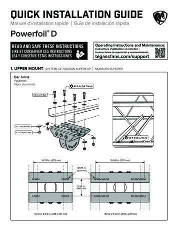
ELEMENT BY BIG ASS FANS 12Mounting Structure: Bar Joists (cont.)5. Attach upper yoke (to angle irons)Secure the upper yoke directly to the angle irons with the Beam Clip Hardware as shown. The angle irons should be aligned with theoutermost holes of the upper yoke. Consult the diagrams below for distances between the angle irons.Tighten the bolts to 40 ft·lb (54.2 N·m) using a torque wrench and 3/4” socket.Beam Clip Hardware (BAF-Supplied):a. (4) 1/2-13 x 2” GR 8 Boltb. (8) 1/2’’ Flat Washerc. (4) 1/2-13 Nylock Nut10-7/8” (27.6 cm)15-5/8” (39.7 cm)Small Upper Yoke13-3/4’’ (34.9 cm) x9-5/8” (24.4 cm)Large Upper Yoke18-1/2’’(46.9 cm) x9-5/8”(24.4 cm)Note: Dashed lines represent angle irons in the above illustrations.Side ViewabbcWWW.BIGASSFANS.COM 2011 DELTA T CORP.ALL RIGHTS RESERVED
ELEMENT BY BIG ASS FANS Hanging the Fan131. Attach extension tube (to upper yoke)Fasten the extension tube to the upper yoke (already attached to I-beam orangle irons) using the Extension Tube Hardware as shown. Before tighteningthe bolts, allow the extension tube to hang freely and balance itself.Tighten the bolts to 40 ft·lb (54.2 N·m) using a 3/8” Allen wrench and a 3/4”socket with torque wrenchExtension Tube Hardware:a. (2) 1/2-13 x 6” Boltb. (4) 1/2” Flat Washerc. (2) 1/2-13 Nylock Nutabbc2. Install trim accessorySlide the trim accessory around the extension tube and raise it to the ceiling. Pinch both retaining clips, slide them through the hole inthe ceiling, and release.CeilingExtension TubeRetaining ClipTrim AccessoryWWW.BIGASSFANS.COM 2011 DELTA T CORP.ALL RIGHTS RESERVED
ELEMENT BY BIG ASS FANS 14Hanging the Fan (cont.)3. Secure upper safety cableThe safety cable is a crucial part of the fan and must be installed correctly. If you have questions, call Customer Servicefor assistance.Secure the safety cable to the I-beam or angle iron by wrapping it around the I-beam or angle iron and securing the looped ends withthe shackle as shown. The cable must be drawn tightly around the I-beam or angle iron, leaving as little slack as possible. If possible,the shackle should be on the topside of the I-beam or angle iron. Securely tighten the shackle.I-Beam MountShackleWWW.BIGASSFANS.COM 2011 DELTA T CORP.Angle Iron MountALL RIGHTS RESERVED
ELEMENT BY BIG ASS FANS 15Hanging the Fan (cont.)4. Attach main fan unit (to extension tube)Do not discard the main fan unit packaging and foam. It should be used if the fan is ever moved or relocated.CAUTION: Do not remove the motor from its protective packagingprior to hanging it!CAUTION: To prevent damage, avoid contact with the printedcircuit board located on the bottom of the fan!cbabCAUTION: The main fan unit is heavy. Use care when raising it.Raise the main fan unit directly from its packaging to the extension tube. Besure to route the lower safety cable into the extension tube. Attach the mainfan unit to the extension tube using the Main Fan Unit Hardware as shown.Tighten the bolts to 20 ft·lb (27.1 N·m) using a 3/8”Allen wrench and a torque wrench and 3/4” socket.Lower Safety CableNote: If installing guy wires, see “Installing Guy Wires”on p. 18.Main Fan Unit Hardware:a. (2) 1/2-13 x 5” Boltb. (4) 1/2” Flat Washerc. (2) 1/2-13 Nylock Nut5. Secure lower safety cableBig Ass Fans recommends completing electrical installation (p. 20) and testing the connections before installing theairfoils.CAUTION: When securing the lower safety cable, be careful not to pinch any electrical wiring that may be routed throughthe extension tube.Remove the access door from the extension tube with a 3/32” Allen wrench. Save thedoor and screws.The lower safety cable is equipped with a pr
ELEMENT BY BIG ASS FANS WWW.BIGASSFANS.COM 2011 DELTA T CORP. ALL RIGHTS RESERVED Operating the Fan Navigating the Controller Menu 28 Speed Selection Screen 30 Active Fan Selection Screen 31