Transcription
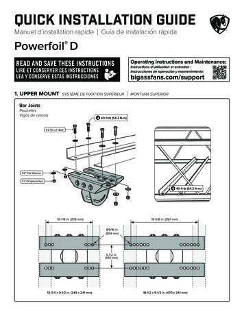
Quick Installation GuideManuel d’installation rapideGuía de instalación rápidaPowerfoil DREAD AND SAVE THESE INSTRUCTIONSLIRE ET CONSERVER CES INSTRUCTIONSLEA Y CONSERVE ESTAS INSTRUCCIONES1. UPPER MOUNTOperating Instructions and Maintenance:Instructions d’utilisation et entretien :Instrucciones de operación y mantenimiento:bigassfans.com/supportSYSTÈME DE FIXATION SUPÉRIEURMONTURA SUPERIORBar JoistsPoutrellesVigas de celosía40 ft·lb (54.2 N·m)1/2-13 x 2" Bolt1/2" Flat Washer1/2-13 Nylock Nut40 ft·lb (54.2 N·m)10-7/8 in. (276 mm)15-5/8 in. (397 mm)Ø9/16 in.(Ø14 mm)5-1/2 in.(140 mm)13-3/4 x 9-1/2 in. (349 x 241 mm)18-1/2 x 9-1/2 in. (470 x 241 mm)
1. UPPER MOUNTSYSTÈME DE FIXATION SUPÉRIEURMONTURA SUPERIORI-BeamPoutre en IViga doble T40 ft·lb (54.2 N·m)1/2-13 x 2" BoltSpacer Entretoise Espaciador(Only if beam flange exceeds 3/8 in. [10 mm])(Si l’aile mesure 10 mm d’épaisseur)(Si el ancho de ala es mayor de 3/8 in. [10 mm])1/2" Flat Washer1/2-13 Nylock NutMounting HolesTrous de fixationOrificios de montajeI-Beam Flange WidthLargeur de l’aile de la poutre en IAncho de ala de la viga doble TA5–6-5/8 in. (127–168 mm)B 6-5/8–8-1/4 in. ( 168–210 mm)C 8-1/4–9-7/8 in. ( 210–251 mm)D 9-7/8–11-3/8 in. ( 251–289 mm)E 11-3/8–13 in. ( 289–330 mm)F 13–14-5/8 in. ( 330–371 mm)FEDSmall MountLarge MountPetit système de fixationMontura pequeñaGrand système de fixationMontura grandeCBA13-3/4 x 9-1/2 in. (349 x 241 mm)18-1/2 x 9-1/2 in. (470 x 241 mm)
2. EXTENSION TUBETIGE DE PROLONGATIONTUBO DE EXTENSIÓNDo not fully tighten hardware.Ne serrez pas la visserie à fond.No ajuste totalmente los accesorios.1/2" Flat Washer1/2-13 x 5" Bolt1/2-13 Nylock Nut3. TIGHTEN HARDWARESERRAGE DE LA VISSERIEAJUSTAR LOS ACCESORIOSAllow extension tube to hang so that it is vertically and horizontally level. Make any necessary angle adjustments toupper mount.Laissez la tige de prolongation pendre librement pour qu’elle se mette d’aplomb et de niveau. Si nécessaire, ajustez l’angle au niveau du systèmede fixation supérieur.Permita que el tubo de extensión cuelgue de manera que esté vertical y horizontalmente nivelado, ajustando los perfiles a la montura superiorsegún sea necesario.40 ft·lb (54.2 N·m)Tighten first.Serrez en premier.Apriete primero.40 ft·lb (54.2 N·m)Side ViewVue latéraleVista lateralFront ViewVue de faceVista frontal
4. UPPER SAFETY CABLEÉLINGUE DE SÉCURITÉ SUPÉRIEURCABLE DE SEGURIDAD SUPERIORThe cable must be drawn tightly around the mounting structure, leaving as little slack as possible.L’élingue doit être enroulée fermement autour de la structure d’ancrage, en laissant le moins de mou possible.El cable se debe envolver firmemente alrededor de la estructura de montaje dejando la menor holgura posible.Angle IronsCornières métalliquesPerfiles angularesShackleI-BeamPoutre en IViga doble TShackle
5. FANVENTILATEURVENTILADORIf your fan order included guy wires, install them according to the instructions included with the guy wire kit.Si vous avez commandé les haubans, installez-les en suivant les instructions fournies avec le kit des haubans.Si junto con su ventilador pidió los cables de sujeción, instálelos de acuerdo con las instrucciones incluidas con el kit de los cables de sujeción.40 ft·lb (54.2 N·m)40 ft·lb (54.2 N·m)Tighten first.1/2-13 x 1-3/4" BoltSerrez en premier.Apriete primero.1/2-13 x 5" Bolt1/2" Flat Washer1/2-13 Nylock Nut10-32 x 1/2" Pan Head Screw1/2" Flat Washer1/2-13 Nylock NutLow Profile MountDirect MountVisit bigassfans.com/supportVisit bigassfans.com/supportRendez-vous sur bigassfans.com/supportRendez-vous sur bigassfans.com/supportVisite bigassfans.com/supportVisite bigassfans.com/supportFixation courteMontura de bajo perfilFixation directeMontaje directo
6. ELECTRICAL INSTALLATIONINSTALLATION ÉLECTRIQUEINSTALACIÓN ELÉCTRICARefer to the provided electrical installation instructions.Reportez-vous aux instructions d’installation électrique fournies.Consulte las instrucciones de instalación eléctrica provistas.7. LOWER SAFETY CABLESÉLINGUES DE SÉCURITÉ INFÉRIEURESCABLES DE SEGURIDAD INFERIORES40 ft·lb (54.2 N·m)1/2-13 x 4-3/4" Bolt1/2" Flat Washer1/2-13 Nylock Nut
8. AIRFOILSPALESASPAS AERODINÁMICASMake sure power is disconnected.Vérifiez que l’alimentation est coupé.Verifique que la alimentación esté desconectada.Do not fully tighten bolts until all retainers are attached. Tighten outer bolts first.Ne serrez pas complètement les boulons à fond tant que toutes les pièces de retenue ne sont pas en place. Serrez les boulons extérieurs en premier.No ajuste totalmente los pernos hasta no aber colocado todos los fijadores. Ajuste los pernos externos primero.5/16-18 x 2" Bolt29 ft·lb (39.3 N·m)5/16" Flat Washer5/16-18 Nylock Nut210-24 x 3/4" Barrel10-24 x 1/2" BoltAHole A should be positioned over top of hole B.Le trou A doit se trouver au-dessus du trou B.El orificio A debe estar ubicado sobre el orificio B.B1
9. HUB COVERCACHE-MOYEUTAPA DEL CUBO10-16 x 1/2" Pan Head Screw10. ACCESSORIESACCESSOIRESACCESORIOSIf your fan order included an accessory, install it according to the instructions that came in the accessory box.Si vous avez commandé un accessoire, installez-le en suivant les instructions fournies.Si junto con su ventilador pidió un accesorio, instálelo de acuerdo con las instrucciones incluidas en la caja del accesorio.11. CONTROLLERDISPOSITIF DE COMMANDECONTROLADORMake sure the controller wiring or cable is routed from the fan to the controller installation location. Refer to theinstructions that came in the controller box for controller installation details.Vérifiez que les fils électriques ou le câble a été tiré jusqu’au site de montage du dispositif de commande depuis le ventilateur. Pour savoir commentinstaller le dispositif de commande, reportez-vous aux instructions fournies.Asegúrese de que el cableado eléctrico o el cable del controlador llegue del ventilador hasta el lugar de instalación del controlador. Los detalles dela instalación los encontrará en las instrucciones que vinieron en la caja del controlador.Conforms to UL 507: Electric FansCertified to CSA C22.2 No. 113: Fans & VentilatorsDDI-INST-261-MUL-01 REV G 03/30/2022 2019 DELTA T LLCALL RIGHTS RESERVED.
The cable must be drawn tightly around the mounting structure, leaving as little slack as possible. L'élingue doit être enroulée fermement autour de la structure d'ancrage, en laissant le moins de mou possible. El cable se debe envolver fi rmemente alrededor de la estructura de montaje dejando la menor holgura posible.