Transcription
BEARING STRENGTH OF COLD FORMED STEEL BOLTEDCONNECTIONS IN TRUSSESMark PanyanouvongThesis Prepared for the Degree ofMASTER OF SCIENCEUNIVERSITY OF NORTH TEXASMay 2012APPROVED:Cheng Yu, Major ProfessorDiane Desimone, Committee MemberHaifeng Zhange, Committee MemberLeticia Anaya, Committee MemberEnrique Barbieri, Chair of theDepartment of EngineeringTechnologyCostas Tsatsoulis, Dean of the Collegeof EngineeringJames D. Meernik, Acting Dean of theToulouse Graduate School
Panyanouvong, Mark. Bearing Strength of Cold Formed Steel BoltedConnections in Trusses. Master of Science (Engineering Systems – ConstructionManagement), May 2012, 109 pp., 9 tables, 14 figures, 11 references.The existing design provision in North American Specification for ColdFormed Steel Structural Member (AISI S100) for the bearing strength of boltedconnections were developed from tests on bolted connected sheets which wererestrained by bolt nut and head with or without washers. However, in the cold-formedassemblies, particularly in trusses, the single bolt goes through both sides of theconnected sections, making the connected sheets on each side unrestrained. Thewarping of the unrestrained sheet may reduce the bearing strength of the boltedconnection. This research investigates the behavior and strength of bearing failure inbolted connections in cold-formed steel trusses. Tensile tests were conducted ontrusses connections with various material thicknesses. It was found that the AISIS100 works well for thick connections but provides unconservative predictions forthin materials. Based on the experimental results, a modified bearing strengthmethod is proposed for calculating the bearing strength of bolted truss connections.The proposed method can be used for any cold-formed steel connections withunrestrained sheet.
Copyright 2012byMark Panyanouvongii
ACKNOWLEDGEMENTSI am heartily thankful to my supervisor, Cheng Yu, whose encouragement,guidance and support from the initial to the final level enabled me to develop andgain greater understanding of the subject. I would like to acknowledge my family andDenial Pisuc who gave me the moral support and for being my back bone. I wouldalso like to give recognition to Stephen Triplett, who was able to help me throughcomposition of this thesis.Many thanks go to Marcus Sanchez and Roger Rovira, whose efforts madethis thesis possible. Lastly, I offer my regards and blessings to all of those whosupported me in any aspect during the completion of the project.iii
TABLE OF CONTENTSPageACKNOWLEDGMENTS . iiiLIST OF TABLES . viLIST OF FIGURES .viiCHAPTER 1 INTRODUCTION . 1CHAPTER 2 BACKGROUND, RESEARCH OBJECTIVES . 32.1Background. 32.2Research Objectives . 4CHAPTER 3 LITERATURE REVIEW . 73.1Research Work and Types of Failure Mode. 73.1.1 Longitudinal Shearing of Steel Sheets (Type I Failure) . 73.1.2 Bearing or Pilling Up of Steel Sheet (Type II Failure) . 83.1.3 Tearing of Sheet in Net Section (Type III Failure) . 83.1.4 Shearing of Bolt (Type IV Failure) . 93.2AISI Design Criteria for Bolted Connections . 103.2.1 Bearing Strength Proposed Methods . 10CHAPTER 4 TESTING. 134.1Testing of Specimens . 134.2Testing Equipment . 154.3Specimens . 164.4Specimens Preparation. 17CHAPTER 5 TEST RESULTS . 195.1Specimen Labeling . 195.2Characterization of Typical Bearing Failure Mode . 205.2.1 Material Properties . 225.3Discussion Proposed Design Method . 23CHAPTER 6 CONCLUSIONS . 29iv
APPENDIX A: DIMENSIONS AND RESULTS OF BOLTED CONNECTIONS IN THEEVALUATION OF EXISTING DATA . 30APPENDIX B: PHOTOGRAPHS AND SPECIMEN CONFIGURATION . 33REFERENCES . 109v
LIST OF TABLESPage3.2.1 Bearing factor C, for bolted connections (AISI S100-2007) . 113.2.2 Modification factor 𝑚𝑓, for type of bearing connection . 114.1.1 Bolt diameter and sizes of bolt holes, inches . 144.1.2 Test matrix of the research project . 145.2.1 Material properties of specimens . 225.3A. Proposed bearing factor, C, for bolted connection . 24B. Proposed modification factor 𝑚𝑓, for bolted connection. 24C. Test-to-predicted ratios for sheet bearing strength . 25D. Resistance factors and AISI factor of safety for proposed design methodsfor bearing in bolted connections . 27vi
LIST OF ILLUSTRATIONSPage2.1Typical failures of bolted CFS connections. 32.2A. Typical sheet to sheet connections . 5B. Typical truss connections . 54.2A. Instron 4482 Universal . 15B. Hydraulic cylinder testing machine . 154.3A. Specimen set up for testing . 16B. Specimen after testing . 164.4Steps to setup the experiment . 175.1Specimens labeling for sheet bearing and shear specimens. 195.2A. Typical curve bearing failure of a bolted connection . 20B. Typical bearing failure of a bolted connection without washers. 20C. Unchanged shape the bearing strength failure of a bolted connectionwithout washers (118mil) . 215.3A. Test results vs. design methods AISI S100 for bearing strength of boltedconnections . 23B. The proposed design vs. design methods AISI S100 for bearing strength ofbolted connections. 25vii
CHAPTER 1INTRODUCTIONCold-formed steel (CFS) is a feasible material in buildings, home, officefurniture, automobiles, equipment, utility poles, highway products, drainagefacilities, and bridges. The popularity of CFS can be ascribed to ease of massproduction and prefabrication, uniform quality, lightweight designs, economyin transportation and handling, fast and simple up righting or installation.CFS structural members shapes are manufactured by pressedbreaking or roll forming cold-or hot-rolled coils or sheets; both formingoperations being performed at ambient room temperature, that is, withoutmanifest addition of heat such as would be required for hot forming. Bucklingusually governs the strength of CFS members for construction.The structural behavior of bolted connections in CFS construction issomewhat different from that in hot-rolled heavy construction, mainly becauseof the thinness of the connected parts. In the U.S., The design provisions forCFS bolted connections are provided in the North American Specification forCold-Formed Steel Structural Member (AISI S100, 2007). Mexico and Canadahave also adopted this specification.1
CHAPTER 2BACKGROUND, RESEARCH OBJECTIVES2.1BackgroundCFS bolted connections may fail in four typical modes as illustrated inFigure 2.1: shear failure of sheet (Type I), bearing failure of sheet (Type II),rupture in the net section (Type III), and shear failure of bolt (Type IV). Thisresearch is focused on the Type II bearing failure of the sheet.Type I Shear Failure of SheetType II Bearing Failure of SheetType III Rupture in the Net SectionType IV Shear Failure of BoltFigure 2.1 Typical Failures of Bolted CFS Connections3
The AISI S100 (2007) provides design provisions for these four typesof failure respectively. AISI S100 provisions for the bearing strength of boltedconnections were developed from tests on sheet connections, in which theconnected sheets were restrained by bolt nut and head with or withoutwashers on both sides of the group of sheets. However in the cold-formedassemblies, for example trusses, framing, racking, etc., the single bolt goesthrough both sides of the connected sections, making the connected elementson each side unrestrained. The unrestrained elements may yield significantout of plan deformation under loading; the deformation may greatly affect thebearing strength of the bolt connection. A comprehensive research project isneeded to investigate the behavior and strength of CFS bolted connectionswith unrestrained elements.2.2Research ObjectivesThis research is aimed at investigating the behavior and strength ofCFS bolted truss connections with unrestrained elements. The investigatedtruss connections contain three elements. The first element used was theweb. The tests used using webs of seven different thicknesses such as:27mil, 33mil, 43mil, 54ml, 68mil, 97mil and 118mil. The second element, thechord had the same seven thicknesses like the web; 27mil, 33mil, 43mil,54mil, 68mil, 97mil and 118mil. With those 23 same thickness combinations ofweb and chords we used for testing our third element, four bolts with differentdiameters; 3/8, 1/2, 5/8 and 3/4 inch. To verify that the results are precise andaccurate; the tests used repeated once for each thickness, for a total of 46tests.4
The main objective for this research is to investigate the behavior andthe strength of bearing failure of bolted connections in cold-formed steel intrusses where the connections in cold-formed steel (CFS) sheets are notrestrained by bolt nut or head on both sides. The bolted connection of thebearing strength of cold-formed steel bolted without nut is presented with thetesting inside of the web having no nut. To determine through mechanicalmethod whether or not having a nut on the inside of the web influences thepeak load.Figure 2.2A Typical sheet to sheetconnectionsFigure 2.2B Typical truss connectionsThis study focused on the different combination of web and chordthickness with varying size bolts. This research also determined the how thefailure points vary based on bolt diameter, web and chord with no support ornut along the inside wall of the web. The experiments conducted were: Examine the difference of the two elements between the web andchord for each configuration. Show the result of the reaction of the web and the chord when the boltsize are different.5
Use different type the bolt size of 3/8, 1/2, 5/8, and 3/4 inch forconnections. Show how the chord and web thicknesses are affected by the lack ofsupport or use of additional washers or nuts inside the web.We compared our experiment testing data to the regular 2-sheet connectedwith a nut.6
CHAPTER 3LITERATURE REVIEW3.1Research Work and Types of Failure ModePrior to 1980, the American Iron and Steel Institute (AISI) determinedthe design specification of bolted connections. These were developed on thebasis of the Cornell tests supervised under the direction of George Winter andother institutes. One of the most recognizable works in this area is theresearch done by Yu (1982).3.1.1. Longitudinal Shearing of Steel Sheets (Type I Failure)Longitudinal shearing of the steel sheet along two almost parallelplanes, where the distance of separation is close to the bolt diameter is aType I Failure. It was discovered by several researchers and they found thatthe shear strength of the sheet type I failure is the relationship between theratio of edge distance 𝑒 and the bolt diameter 𝐶which indicate the bearingstress at failure can be predicted byσbFuwhere σ b ed(Eq.3.1A)Ultimate bearing stress between bolt and connected part,ksiFuTensile strength of connected part, ksieEdge distance, in.dBolt diameter, in.7
3.1.2 Bearing or Piling Up of Steel Sheet (Type II Failure)When the edge distance is sufficiently large or when we have large 𝑒 𝐶ratios, the failure of connections may occur in front of the bolt. The Universityof Missouri-Rolla conducted the research on the failure and recognized thatthe hole extension prior to reaching the bearing strength, limited a boltedconnection. The limitation of the connection movement was 0.25 in. or (6.4mm). The deformation around the bolt holes ( Pn ) is a design consideration,according to the Supplement to the 1996 edition of the Specification [1.333]: isgiven by:Pn (4.6t 1.53)dt Fu(with t in inches)(Eq.3.1B.1)For SI units:Pn (0.831t 1.53)dt Fu (with t in mm)where: t(Eq.3.1B.2)Thickness of connected partdDiameter of bolt (in.)FuTensile strength of steel (ksi) or (MPa)PnBearing strength3.1.3 Tearing of Sheet in Net Section (Type III failure)Cornell University conducted the tests by using connections under bolthead and nut to eliminate the stress concentration for the low ductility steel. In1992, Zadoanfarrokh and Bryan investigated the shear failure and bearingfailure in connections sheets. In order to prevent the rupture failure the width𝑤 of the specimens’ connection has to be sufficiently large and thus set up(w 6.25d) for bearing tests with the nominal bolt diameter d 0.4 in. Besides8
finding the type III failure of tearing of sheet in the net section, the effects ofthe 𝐶 𝑠 ratio on the tensile strength of bolted connections with washers wereobserved.The following formulas have been developed to predict the failure stress in thenet section:a)b)Where 𝜎𝑛𝑒𝑡When 𝐶 𝑠 0.3,When 𝐶 𝑠 0.3,𝜎𝑛𝑒𝑡 [ 1- 0.9r 3r(d/s)]𝐶𝑢 𝐶𝑢𝜎𝑛𝑒𝑡 𝐶𝑢(3.1C.A)(3.1C.B)Failure stress in net section, ksirForce transmitted by bolt or bolts at the section considered,divided by the force in the member at that sectiondBolt diameter, in.sSpacing of bolts perpendicular to line of stress, in.𝐶𝑢Ultimate tensile strength of steel sheets, ksi3.1.4 Shearing of Bolt (Type IV Failure)The shearing of bolt failure is the type of failure by shearing of the boltthat occurs at the strength equal to 0.6 times the tensile strength of the bolt[Yu, 2000]. For the type IV failure, this research was not focus on this mode offailure.9
3.2AISI Design Criteria for Bolted ConnectionsThe design bearing strength of bolted connections shall be determinedby the design bearing strength of bolted connections by tests, 𝑃𝑛 , bearingfactor, C, to account for the influence by the bolt diameter to sheet thicknessratio, 𝐶 𝑡. A modification factor is used to reflect the washer option as well asconnection type for single shear connections without a washer with standardholes, ( 𝑚𝑓 0.75 ).3.2.1 Bearing Strength Proposed MethodsThe bearing strength of bolted connections with standard holes isshown in equation 3.2-1 (𝐸𝑞 . E3.3.1-1 of AISI S100 2007). When deformationaround the bolt holes is not a design consideration, the nominal bearingstrength [resistance], 𝑃𝑛 , of the connected sheet for reach loaded boltdetermined as follows:where𝑃𝑛 𝑚𝑓 Cdt𝐶𝑢(Eq. 3.2.1)CBearing factor, which shall be determined according toTable 3.3.1.dNominal bolt diametertUncoated sheet thicknessFuTensile strength of sheet as defined𝑚𝑓Modification factor for type of bearing connection, whichshall be determined according to Table 3.2.2.USA and MexicoΩ (ASD)ɸ (LRFD)2.500.6010Canadaɸ (LSD)0.50
Table 3.2.1 Bearing Factor, C, for Bolted Connections (AISI S100 2007)Thickness ofConnected Part, t,(inch) (mm)Ratio of FastenerDiameter to MemberThicknessCd/td/t 103.010 d/t 224 – 0.1(d/t)d/t 221.80.024 t 0.1875(0.61 t 4.76)Table 3.2.2 Modification Factor, 𝑚𝑓 , for Type of Bearing ConnectionType of Bearing Connection𝑚𝑓Single Shear and Outside Sheets of DoubleShear Connection with Washers under BothBolt Head and Nut1.00Single Shear and Outside Sheets of DoubleShear Connection without Washers underBoth Bolt Head and Nut, or with only onewasher0.75Inside Sheet of Double Shear Connectionwith or without Washers111.33
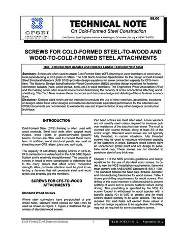
CHAPTER 4TESTING4.1Testing of SpecimensWe will compare our experiment testing data to the regular 2-sheetconnected with a nut. CFS steel sheet nominal thickness range from 27mil to 118mil withminimum yield strength from 33 ksi to 50 ksi. Bolted Connections is referring to the design criteria and therequirements for the bolted connections used for cold-formed steelstructural members in which the thickness of the thinnest connectedpart is less than 3/16 in. (4.76 mm). [1] American Society for TestingMaterial (ASTM), A307 (Type A) bolts, carbon steel bolts and studs,have less than 60,000 PSI Tensile Strength for bolts with nominaldiameters of 3/8, 1/2, 5/8 and 3/4 in. Minimum Edge and End Distances according to AISI S100 (2007). Theminimum distance between centers of bolt holes shall provide sufficientclearance for bolt holes and shall provide sufficient clearance for boltheads, nuts, washers. Also the wrench shall not be less than 3 timesthe nominal bolt diameter, d. (e 3d).13
Table 4.1.1 Bolt diameter and Sizes of Bolt Holes (inches)Nominal bolt diameter, d(in.)AISI Standard HoleDiameter d (in.)3/813/321/29/165/811/163/413/16Note: 1 in. 25.4 mm.Table 4.1.2 Test matrix of the research projectWeb with Chord (mil.)Nominalbolddiameter(in.)27 x 2733 x 3343 x 4354 x 5468 x 6897 x 97118 x 1183/8 inchYesYesYesYesYesNONO1/2 inchYesYesYesYesYesYesYes5/8 inchYesYesYesYesYesYesYes3/4 inchYesYesYesYesNONONOWe repeat each configuration once, resulting in a total of 46 tests.14
4.2Testing EquipmentThe testing was separated by two machines to properly test the varyingweb and chord thicknesses. For thickness of 27mil to 97mil, a 20 kip capacityInstron 4482 universal testing machine was used. For the thickness of 118mil,the test was performed at the high-bay area by the hydraulic cylinder that isable to handle over 20 kip as shown in Fig.4.2B. Most tests conducted werestopped shortly after the deformation point and once maximum load had beenachieved as shown in Fig.4.2A.Figure 4.2A Instron 4482 Universal15Figure 4.2B Hydraulic CylinderTesting Machine
4.3SpecimensThe same sheet steel thicknesses were used for the web and the chordfor each of the 46 tests to create the specimens with 4 different kinds of bolt.A coupon test was performed for every thickness in order to get the yieldstress 𝐶𝑦 , ultimate stress 𝐶𝑢 , and the thickness of the sheet steel andpercentage of elongation. Each thickness was tested 3 times in order toachieve the same results and determine that the tests were precise.t1de 3dt2Figure 4.3ASpecimen setup for testingFigure 4.3BSpecimen after testing16
4.4Specimens PreparationTwo sheets steel with the same thickness were cut into 2 pieces,measurement based upon the testing specifications for each and every test.The hole punch distance varies with the bolt diameter used as according theAISI standard hole diameter specification as shown in the Figure 4.4.Figure 4.4 Steps to setup the experiment17
The sheets were then folded using a brake press machine with the webfold points slight closer so that the web will accurately fit into the chord.The web and chord were connected by the bolt specimen based on thetest specifications and secured with a nut to insure the body of the boltspecimen was within the testing area of the web and chord and that thethreads of the bolt would not create a point of failure during the tests. Thetesting specimens were connected to the testing machine using mountingbrackets to insure the load of the machine is being evenly distributed acrossspecimen.18
CHAPTER 5TEST RESULTSThe testing results and the geometric properties can be found in theAppendices (Table A1, A2, A3 and A4). Here, it is also included thecomparison between the bearing strength of the actual test capacity and thenew bearing capacity calculated with adjustment with preferable the ratio𝑃closest to one ( 𝑡𝑒𝑠𝑡 𝑃𝑛𝑒𝑤 1). The comparisons are shown in the Table A1(Appendix A).5.1Specimen LabelingThe labeling specimens were assigned by the same format to identify the testspecimens:33-1/2-T1Web/Chord Thickness in milTest NumberNominal diameter of bolt ininchesFigure 5.1 Specimens Labeling for Sheet Bearing and Shear Specimens19
5.2Characterization of Typical Bearing Failure ModeThe graph below illustrates the typical curve of the bearing failure forthe specimens. With the initial load applied, the sheet steels experiencedslippage against the bolt. With the load still being applied, sheets steel startedyielding at to the maximum load. At which point the specimen continued todeform and stopped the testing at around 1 or 1.2 inch.Applied load per bolt (lbs.)18000Bearing FailureMaximum load1600014000Plastic Deformation1200010000Elastic Deformation80006000400020000Sheets and Bolt Slippage00.20.40.60.811.2Displacement (inch)Figure 5.2A Typical curve bearing failure of a bolted connectionFigure 5.2B Typical bearing failure of a bolted connection without washers201.4
In this research 46 experiments with 4 different sizes of bolts wereconducted. The chord and the web connections when the load was appliedwere observed. Since, there was no support along the inside wall of the web,the testing results showed the reaction of the web conformed to the perimetercontour after the load applied as shown in Figure 5.2B., resulting in type IIfailures or piling during tests. The same reaction also occurred with samethickness of testing from 27mil until 97mil. In contrast, for the sheets steelconnections of 118mil, the results of the shape remaining unchanged after themaximum load was reached and the test was stopped here. Great elongationwas observed in this case as shown in Figure 5.2C. Due to the thickness ofthe 118mil steel, most failures were type I, (failure of the steel sheet).Figure 5.2CUnchanged shape the bearing strength failure of a boltedconnection without washers (118mil)21
5.2.1 Material PropertiesCoupon tests were conducted according to ASTM 307 (2007)“Standard Test Method and Definitions for Mechanical Testing of SteelProducts” to obtain the actual properties of the test materials in this research.The coupon test results are summarized in Table 5.2. The coating on the steelwas removed by hydrochloric acid prior to the coupon tests. The couponstests were conducted on the INSTRON 4482 universal testing machine. AnINSTRON was employed to measure the tensile strain. The tests wereconducted in displacement control at a constant rate of 0.05 in./min. A total offour coupons were tested for each member, and the average results areprovided in Table 5.2.1Table 5.2.1 Material Properties of specimensNominalsheetthickness27 mil33 mil43 mil54 mil68 mil97 mil118 .06980.10170.1305Actual 𝐶𝑦(ksi)Actual �1.151.211.211.301.181.081.15Elongationon high10.00%high15.50%high10.00%high16.90%high
5.3Discussion Proposed Design MethodAccording to previous research (LaBoube and Yu 1995, Wallace,Schuster, and LaBoube 2001a), the experience adopted the same equations(Eq. E3.3.1-1) for the bearing failure of bolted connections based on the AISIS100 (2007) specifications as bearing factor C and the modification factor 𝑚𝑓listed on Table 3.2.2 and 3.2.3 respectively for bearing single shear andoutside sheets of double connection without washers uses 𝑚𝑓 0.75.After the test results achieved and compared to the current AISI S100predictions are lower than predictions when the ratio of d/t had a big number.In order to accurately predict the bearing strength, the research revised theformula of the bearing factor, C, and the modification factor, 𝑚𝑓 .4.00Data Testing3.50Current AISIS100 DesignP/(Fu 0.0025.0030.0035.0040.00d/tFigure 5.3A Test Results vs. Design Methods AISI S100 for Bearing Strengthof Bolted Connections23
A new bearing factor and modification factor (Table 5.3A) wereproposed in order for the test results to be more in line with the original AISIS100 standard. The Y-axis represents the normalized peak loads, 𝑃𝑡𝑒𝑠𝑡 /(𝐶𝑢 𝐶𝑡),which is equivalent to the value of the bearing factor and modification factor(C 𝑚𝑓 ). The new proposed method adopted a non-linear curve for the C factorin order to get the factor of safety and resistance factor approach to AISI S100values.Table 5.3AProposed Bearing Factor, C, for Bolted connectionRatio of fastener diameter to memberthickness, d/tNew Method for Bearing Factor Cd/t 535 d/t 280.33 13.33/(d/t)d/t 280.81Table 5.3BProposed Modification Factor,𝑚𝑓 , for Bolted ConnectionType of Bearing ConnectionSingle Shear and Outside Sheets ofDouble Shear Connection withoutWashers under Both Bolt Head and Nut24𝑚𝑓0.675
𝑃𝑛 /(𝐶𝐶𝐶𝑢 )Current AISIProposed DesignData from Testingd/tFigure 5.3B The Proposed Design vs. Design Methods AISI S100 forBearing Strength of Bolted ConnectionsThe ratio for the new design method is 𝑃𝑡𝑒𝑠𝑡 /𝑃𝑛𝑒𝑤 . The new methodgives an average test ratio of 1.05, with a standard deviation of 0.28 andcoefficient of 0.24.Table 5.3CHole config.TrussesconnectionsTest-to-Predicted Ratios for Sheet Bearing StrengthNo. oftests46𝑃𝑇𝑒𝑠𝑡 𝑃𝑇𝑒𝑠𝑡 /𝑃𝑁𝑒𝑤Avg.Std.COVdev.1.160.280.24
Proposing bearing strength method, the resistance factor ɸ for (LRFD)and factor of safety Ω (ASD) were determined according Chapter F of AISIS100 (2007), with a target reliability index 3.5 for connections for the LRFD.Considering the equation Eq.5.3A and from AISI S100 (2007) Eq. F1.1-2 theresistance factor ɸ can be determined as follows:where:ɸ 𝐶ɸ (𝑀𝑚 𝐶𝑚 𝑃𝑚 ) 𝑒 𝛽0 𝑉𝑀2 𝑉𝐹2 𝐶𝑃 𝑉𝑃2 𝑉𝑄2Eq.5.3A𝐶ɸCalibration coefficient 1.52 for the United States𝑀𝑚Mean value of material factor, M, listed in Table F1 for type ofcomponent involved (AISI S100-2007)𝐶𝑚Mean value of fabrication factor, F, listed in Table F1 for type ofcomponent involved (AISI S100-2007)𝑃𝑚Mean value of professional factor, P, for tested component𝛽0Target reliability index 3.5 for the United States𝑉𝑀Coefficient of variation of material factor listed in Table F1 fortype of component involved𝑉𝐹Coefficient of variation of fabrication factor listed in Table F1 fortype of component involved𝐶𝑃Correction factor (1 1/n)m/(m-2) for n 4𝑉𝑃Coefficient of variation of test results, but not less than 6.5%mDegree of freedom (n-1)nNumber of tests𝑉𝑄Coefficient of variation of load effect 0.21𝑒Natural logarithmic based 2.71826
According to the AISI, by knowing the resistance factor, ɸ, thecorresponding safety of factor can be computed as follows:Ω 1.533Eq.5.3BɸThe resistance factor ɸ and the factor of safety Ω can be determinedbased upon the test results and the calibrations AISI S100 (2007), Table F1 ofthe bolted connections with and without washersTable 5.3D: Resistance Factors and AISI factor of Safety for ProposedDesign Methods for Bearing in Bolted ConnectionsNumber of SpecimensMeanStd. Dev.COV (𝑉𝑃 β(LRFD)𝑉𝑄ɸ (LRFD)Ω 21AISI S1000.62.560.62.50The new method yielded an equivalent resistance factor of 0.6compared to AISI S100 standard, while the safety factor was slightly higherthan the AISI S100 standard value. Based on the testing value and similarequation values, the AISI S100 would be acceptable to adapt to the sametype of connection.27
CHAPTER 6CONCLUSIONA total of 46 CFS bolted truss connections were tested in this research.The specimen parameters include the thickness of the material and the boltdiameter. The experimental results show that the truss connections with thickmaterials (118mil and 97mil) do not demonstrate significant out of plandeformation in the unrestrained elements. The existing AISI provisions givegood prediction for the beating strength of those connections. However forthin materials (68 mil or thinner), significant out of plane deformation wasobserved, the test results of those connections are lower than the AISIpredictions. On average,
trusses where the connections in cold-formed steel (CFS) sheets are not restrained by bolt nut or head on both sides. bolted connection of the The bearing strength of coldformed steel bolted without nut is- presented with the testing inside of the web no nut. havingTo determine through mechanical method whether or not having a nut on the inside .