Transcription
Design No. P573June 01, 2020Restrained Assembly Rating - 1, 2 Hr (see Item 5, 5A, and 5B)Unrestrained Assembly Rating - 1, 2 HrThis design was evaluated using a load design method other than the Limit States DesignMethod (e.g., Working Stress Design Method). For jurisdictions employing the Limit StatesDesign Method, such as Canada, a load restriction factor shall be used — SeeGuide BXUV or BXUV7* Indicates such products shall bear the UL or cUL Certification Mark for jurisdictionsemploying the UL or cUL Certification (such as Canada), respectively.
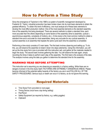
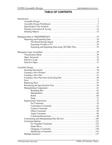
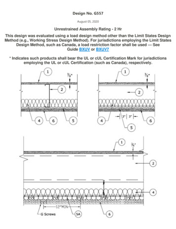
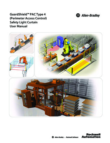
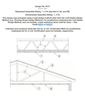
1. Structural Steel Members* — Pre-fabricated light gauge steel truss system consisting of cold-formed, galvanizedsteel cord and web sections. Trusses fabricated in various sizes, depths, and from various steel thickness. Trussesminimum 12 in. deep, spaced a max of 48 in. OC.AEGIS METAL FRAMING, DIV OF MITEK — Ultra-Span, Pre-fabricated Light Gauge Steel Truss SystemTRUSSTEEL, DIV OF ITW BUILDING COMPONENTS INC — TrusSteel1A. Steel Roof Trusses — As an alternate to Item 1 - Cold-formed galvanized steel truss chord and web sectionsmanufactured from steel conforming to ASTM A653 Grade 33 or higher yield strength. Steel thickness of truss chordand web sections as required by design to meet governing code requirements. Truss members connected togetherwith No. 10-16 (min size) self-drilling screws or equivalent. Truss chord and web members to be designed inaccordance with the American Iron and Steel Institute's Specification for the Design of Cold-Formed Steel StructuralMembers, 1996 Edition. Trusses spaced a max of 48 in. OC. Where the truss intersects with the interior face of theexterior walls, the min truss depth shall be 12 in.1B. Steel Joists — As an alternate to Item 1 or 1A, minimum 12K1, spaced a max 48 in. OC.1C. Structural Steel Members* — ((Not Shown) - As an alternate to Item 1, 1A, and 1B, - Pre-fabricated steel trusssystem consisting of cold-formed, galvanized steel chord and web sections. Truss top and bottom chords min. 4 in.high by 1-11/16 in. wide by 18 ga. Truss webs min. 1-1/2 in. by 1-1/2 in. by 20 ga. square tube bent and triangulatedas shown. Chords and web connected by fillet welds. Minimum truss depth min. 12 in. Trusses spaced a max of 24 in.OC. Truss ends placed over and secured to Bearing Seats (Item 1C1) with two min. #10 by 3/4 in. long screws on eachside of Bearing Seats. Allowable loading must be calculated so as to stress the steel trusses to a maximum of 98% ofthe stress calculated in accordance with the allowable stress design approach outlined in the manufacturer's loadtables.EISEN PANEL SYSTEMS L L C — Type Gateway Panel pre-fabricated steel truss system.1C1. Bearing Seats* — (Not Shown) — Galvanized steel tube, min. 1 in. by 2-1/2 in. by 13 ga., oriented vertically andwelded to min. 4 in. by 4 in. by 10 ga., galvanized steel plate. Bearing seats spaced 24 in. OC and attached to bearingsupports by welding or screw attaching the steel plate to the bearing supports.EISEN PANEL SYSTEMS L L C — Type Gateway Panel bearing seat.
1C2. Bracing — (Not Shown) - For use with Item 1C — Galvanized channel-shaped steel sections, min. 1-1/2 in. widewith 1/4 in. flanges, min. 16 ga. Bracing attached to underside of trusses with min. #10 by 3/4 in. long screws throughtruss bottom chord. Bracing installed in truss cavities by scoring, bending and flattening the ends to form a tab forattachment to truss top and bottom chords. Two pieces of bracing crossed and tabs secured to truss chords with min.#10 by 3/4 in. long screws. Location and spacing of underside and crossed bracing to be specified on trussengineering.1D. Structural Steel Members* — As an alternate to Item 1 - Limited to the 1 Hour Ratings. Pre-fabricated lightgauge steel truss system consisting of cold-formed, galv steel cord and web sections. Trusses fabricated in varioussizes, depths and from various steel thickness. Trusses spaced a max of 24 in. OC. Location of lateral bracing for trusschord and web sections to be specified on truss engineering.TRUSS LINK INC — Truss Link2. Bridging — (Not Shown) — Location of lateral bracing for truss chord and web sections to be specified on trussengineering.3. Structural Cement-Fiber Units* — Nom 3/4 in. thick, square or T&G edge, with long dimension of panels to beperpendicular to truss with end joints staggered a min of 4 ft and centered over the trusses. Panels secured to steeltrusses with 1-5/8 in. long No. 8 self-drilling, self-countersinking steel screws spaced a max of 12 in. OC in the fieldwith a screw located 1 in. from each edge, and 8 in. OC at the perimeter, screw attached to the runner track (Item 4),located 1 in. from the edge. At the end joints, screws 8 in. OC with a screw located 2 in. from each edge, located 1/2 in.from the end edges of the panel.As an alternate to the 1-5/8" long No. 8 fastener, the following power-actuated pins may be used for min. 1/8" thick,hot-rolled A36 steel sections for joist specified in Item 1B:Hilti pin model X-U 32MX with a min. 0.157" shank diameter min. 1-1/4" long, DeWalt pin model 50458-PWR with amin. 0.157" shank diameter min. 1-1/4" long or Aerosmith model 5324HPG with a min. 0.145 shank diameter min. 11/4" long. Note that these pins shall not be used to fasten the cement panels to the runner track (Item 4).UNITED STATES GYPSUM CO — Types STRUCTO-CRETE, USGSP.4. Runner Track — For use with Item 3 - Not Shown - Channel shaped runners, min 3-5/8 deep, 1-1/4 in. legs, formedfrom min No. 16 MSG galv steel, centered and located under all long structural cement-fiber unit (Item 3) jointsperpendicular to trusses. Runner tracks ends centered and butted together over truss and legs notched to allowrunner track to lay flat on top of truss upper chord. Runner track not attached to truss except when screws fromattachment of structural cement-fiber unit penetrate both runner track and truss.5. Roof Insulation — Foamed Plastic* — Any polyisocyanurate foamed plastic insulation boards bearing the ULClassification Marking. No min thickness for the 1 hr assembly ratings. Min thickness is 1 in. for the 2 hr assemblyrating, with no limit on max overall thickness. As an alternate to roof insulation, min. 6 in. batts and blankets (Item 8)shall be fitted in the concealed space, draped over the furring channels for the 2 hr rating. Boards installed over thestructural cement-fiber units (Item 3), with the end-joints staggered in adjacent rows. When applied in more than onelayer, each layer of board to be offset from layer below in order to lap all joints. Boards loosely laid, adhered ormechanically fastened to structural cement-fiber units (Item 3). See Foamed Plastic (CCVW) Category in the FireResistance Directory.5A. Roof Insulation — Foamed Plastic* — (Not Shown) As an alternate to Item 5 Any polystyrene foamed plasticinsulation boards bearing the UL Classification Marking. No min thickness for the 1 hr assembly ratings. Min thickness
is 1 in. for the 2 hr assembly rating with no limit on max overall thickness. As an alternate to roof insulation, min. 6 in.batts and blankets (Item 8) shall be fitted in the concealed space, draped over the furring channels for the 2 hr rating.Boards installed over the structural cement-fiber units (Item 3) with the end-joints staggered in adjacent rows. Boardsloosely laid, adhered or mechanically fastened to cement-fiber units (Item 3). See Foamed Plastic (BRYX) category inthe Building Materials Directory or Foamed Plastic (CCVW) category in the Fire Resistance Directory.5B. Roof Insulation — Mineral and Fiber Boards* — (Not Shown) — As an alternate to Item 5 — Mineral wool, glassfiber or perlite insulation boards, 24 by 48 in. min size. No min thickness for the 1 hr assembly ratings. Min thickness is1 in. for the 2 hr assembly rating with no limit on max overall thickness. As an alternate to roof insulation, min. 6 in.batts and blankets (Item 8) shall be fitted in the concealed space, draped over the furring channels for the 2 hr rating.Boards installed over the structural cement-fiber units (Item 3) with the end-joints staggered in adjacent rows. Boardsloosely laid, adhered or mechanically fastened to cement-fiber units (Item 3). See Mineral and Fiber Boards (BQXR)Category in the Building Materials Directory or Mineral and Fiber Boards (CERZ) Category in the Fire ResistanceDirectory.5C. Roof Cover Board - Gypsum Board* (Not Shown) — As an alternate to Item 5 for a 2 hr rating. Min 1/2 in. thick(one layer), 4 ft by 4 ft gypsum roof cover board, adhered or mechanically fastened with a minimum of 5 fasteners perboard.UNITED STATES GYPSUM CO — Type FRX-G5D. Roof Cover Board - Gypsum Board* (Not Shown) — As an alternate to Item 5 for a 2 hr rating. Min 1/2 in. thick(one layer), 4 ft by 4 ft gypsum roof cover board, adhered or mechanically fastened with a minimum of 5 fasteners perboard.UNITED STATES GYPSUM CO — Type SGMRX5E. Roof Cover Board - Cementitious Backer Units* (Not Shown) — As an alternate to Item 5 for a 2 hr rating. Min1/2 in. thick (one layer), 4 ft by 4 ft gypsum roof cover board, adhered or mechanically fastened with a minimum of 5fasteners per board.UNITED STATES GYPSUM CO — Type DCB6. Roofing Membrane* — (Not Shown)—Single-ply membrane that is either ballasted, adhered or mechanicallyattached to the insulation(s) described herein as permitted under the respective company's Classification. See FireResistance Directory, Roofing Membranes (CHCI) category.7. Furring Channels — Hat channels min 25 MSG galv steel, min 2-5/8 in. wide by min 7/8 in. deep, installedperpendicular to the trusses (Item 1), spaced a max of 12 in. OC when batts and blankets (item 8) or loose fill material(item 8A) are used and a max of 16 in. OC when they are not. Two courses of channel positioned 6 in. OC, 3 in. on eachside of gypsum board end joints. Channel splices overlapped 4 in. beneath steel trusses. Channels secured to eachtruss with No. 18 SWG steel wire double strand saddle ties.7A. Steel Framing Members — Not Shown -As an alternate to Item 7a. Main runners — Installed perpendicular to Structural Steel Members — Nom 10 or 12 ft long, 5/16 in. or 11/2 in. wide face, spaced 4 ft OC. Main runners hung a min of 2 in. from bottom chord of Structural SteelMembers with 12 SWG galv steel wire. Wires located a max of 48 in. OC.b. Cross tees or channels — Nom 4 ft long, 15/16 in. or 1-1/2 in. wide face or cross channels, nom 4 ft long,1-1/2 in. wide face, installed perpendicular to the main runners, spaced 16 in. OC. Additional cross tees or
channels used at 8 in. from each side of butted gypsum board end joints. The cross tees or channels may beriveted or screw-attached to the wall angle or channel to facilitate the ceiling installation.c. Wall angles or channels — Used to support steel framing member ends and for screw-attachment of thegypsum board — Min 0.016 in. thick painted or galvanized steel angle with 1 in. legs or min. 0.016 in. thickpainted or galvanized steel channel with a 1 by 1-1/2 by 1 in. profile, attached to walls at perimeter of ceilingwith fasteners 16 in. OC.USG INTERIORS LLC — Type DGL or RX.7B. Alternate Steel Framing Members* — (Not Shown) - As an alternate to Item 7A - Not for use with Items 8 or 8A- Main runners nom 12 ft long, spaced 72 in. OC. Main runners suspended by min 12 SWG galv steel hanger wiresspaced 48 in. OC. Cross tees, nom 6 ft long, installed perpendicular to main runners and spaced 24 in. OC. Additional 6ft long cross tees required at each gypsum board end joint with butted gypsum board end joints centered betweencross tees spaced 8 in. OC. The main runners and cross tees may be riveted or screw attached to the wall angle orchannel to facilitate the ceiling installation.USG INTERIORS LLC — Type DGL or RX7C. Steel Framing Members* - (Not Shown) — As an alternate to Items 7 to 7B, furring channels and Steel FramingMembers* as described below:a. Furring Channels — — Formed of No. 25 MSG galv steel, 2-9/16 in. or 2-23/32 in. wide by 7/8 in. deep,installed perpendicular to the trusses (Item 1), spaced a max of 12 in. OC when batts and blankets (Item 8) orloose fill material (Item 8A) are used and a max of 16 in. OC when they are not. Channels secured to trusses asdescribed in Item b. Ends of adjoining channels overlapped 6 in. and tied together with double strand of No.18 SWG galv steel wire near each end of overlap.b. Steel Framing Members* — Used to attach furring channels (Item a) to the steel joists (Item 1). Clipsspaced a max of 48 in. OC. RSIC-1 and RSIC-1 (2.75) clips secured to alternating joists with No. 8 x 2-1/2 in.coarse drywall screw through the center grommet. Furring channels are friction fitted into clips. RSIC-1 clips foruse with 2-9/16 in. wide furring channels. RSIC-1 (2.75) clips for use with 2-23/32 in. wide furring channels.Adjoining channels are overlapped as described in Item a. As an alternate, ends of adjoining channels may beoverlapped 6 in. and secured together with two self-tapping No. 6 framing screws, min. 7/16 in. long at themidpoint of the overlap, with one screw on each flange of the channel. Additional clips required to holdfurring channel that supports the wallboard butt joints, as described in Item 9.PAC INTERNATIONAL L L C — Types RSIC-1 or RSIC-1 (2.75)8. Batts and Blankets — Optional — Any thickness mineral wool or glass fiber insulation bearing the UL ClassificationMarking for Surface Burning Characteristics, having a flame spread value of 25 or less and a smoke spread value of 50or less. Insulation fitted in the concealed space, draped over the resilient channel/gypsum board ceiling membrane.8A. Loose Fill Material — Optional — As an alternate to Item 8 - Any thickness of loose fill material bearing the ULClassification Marking for Surface Burning Characteristics, having a flame spread value of 25 or less and a smokespread value of 50 or less. Insulation fitted in the concealed space, draped over the resilient channel/gypsum boardceiling membrane.9. Gypsum Board* — One layer of nom 5/8 in. thick by 48 in. wide boards, installed with long dimension parallel totrusses. Attached to the furring channels using 1 in. long Type S bugle-head screws spaced 12 in. OC along buttedend-joints and 12 in. OC in the field when no insulation (Item 8 or 8A) is fitted in the concealed space or a max 8 in.OC along butted end-joints and in the field when insulation (Item 8 or 8A) is fitted in the concealed space, draped
over the furring channel/gypsum board ceiling membrane. When Steel Framing Members (Item 7C) is used, the buttjoints in the gypsum board shall be supported by two furring channels. The two furring channels shall be spacedapproximately 3-1/2 in. OC, and be attached to underside of the joist with one RSIC-1 or RSIC-1 (2.75) clip at each endof the channel. Gypsum board attached to the furring channels using 1 in. long Type S bugle-head screws spaced 8 in.OC along butted end-joints and 12 in. OC in the field when no insulation (Item 8 or 8A) is fitted in the concealedspace.UNITED STATES GYPSUM CO — Type CCGC INC — Type ULIXUNITED STATES GYPSUM CO — Type ULIX10. Gypsum Board* — For use with Steel Framing Members (Item 7A or 7B) when Batts and Blankets* (Item 8 or8A) are not used - One layer of nominal 5/8 in. thick by 48 in. wide boards, installed with long dimension parallel tothe main runners. Gypsum board fastened to each cross tee or channel with five gypsum board screws, with one screwlocated at the mid-span of the cross tee or channel, one screw located 12 in. from and on each side of the cross tee orchannel mid-span, and one screw located 1-1/2 in. from each gypsum board side joint, Except at gypsum board endjoints, gypsum board screws shall be located on alternating sides of cross tee flange. At gypsum board end joints,gypsum board screws shall be located 1/2 in. from the joint. Gypsum board fastened to main runners with gypsumboard screws 1/2 in. from side joints, midway between intersections with cross tees or channels (16 in. OC). End jointsof adjacent gypsum board sheets shall be staggered not less than 32 in. Gypsum board sheets screw attached to legof wall angle with gypsum board screws spaced 12 in. OC. Joints treated as described in Item 10. For use with SteelFraming Members* (Item 7A) when Batts and Blankets* (Item 8) are used - - Ratings limited to 1 Hour- 5/8 in. thick,4 ft wide; installed with long dimension perpendicular to cross tees with side joints centered along main runners andend joints centered along cross tees. Fastened to cross tees with 1 in. long steel gypsum board screws spaced 8 in. OCin the field and 8 in. OC along end joints. Fastened to main runners with 1 in. long gypsum board screws spacedmidway between cross tees. Screws along sides and ends of boards spaced 3/8 to 1/2 in. from board edge. End jointsof the sheets shall be staggered with spacing between joints on adjacent boards not less than 4 ft OC.UNITED STATES GYPSUM CO — Type C10A. Gypsum Board* — For use with Steel Framing Members* (Item 7A) when max 3-1/2 in. Batts andBlankets* (Item 8) are used - - Ratings limited to 1 Hour- 5/8 in. thick, 4 ft wide; installed with long dimensionperpendicular to cross tees with side joints centered along main runners and end joints centered along cross tees.Fastened to cross tees with 1 in. long steel gypsum board screws spaced 8 in. OC in the field and 8 in. OC along endjoints. Fastened to main runners with 1 in. long gypsum board screws spaced midway between cross tees. Screwsalong sides and ends of boards spaced 3/8 to 1/2 in. from board edge. End joints of the sheets shall be staggered withspacing between joints on adjacent boards not less than 4 ft OC.CGC INC — Type ULIXUNITED STATES GYPSUM CO — Type ULIX11. Finishing System — (Not Shown) — Vinyl, dry of premixed joint compound, applied in two coats to joints andscrew heads, paper tape, 2 in. wide, embedded in first layer of compound over all joints.
* Indicates such products shall bear the UL or cUL Certification Mark for jurisdictionsemploying the UL or cUL Certification (such as Canada), respectively.Last Updated on 2020-06-01
Trusses minimum 12 in. deep, spaced a max of 48 in. OC. AEGIS METAL FRAMING, DIV OF MITEK — Ultra-Span, Pre-fabricated Light Gauge Steel Truss System TRUSSTEEL, DIV OF ITW BUILDING COMPONENTS INC — TrusSteel 1A. Steel Roof Trusses — As an alternate to Item 1 - Cold-formed galvanized steel truss chord and web sections