Transcription
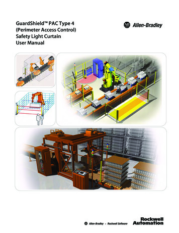
GuardShield PAC Type 4(Perimeter Access Control)Safety Light CurtainUser Manual
Important User InformationBecause of the variety of uses for the products described in this publication, those responsible for theapplication and use of this control equipment must satisfy themselves that all necessary steps have beentaken to assure that each application and use meets all performance and safety requirements, includingany applicable laws, regulations, codes and standards.The illustrations, charts, sample programs and layout examples shown in the guide are intended solely forpurposes of example. Since there are many variables and requirements associated with any particularinstallation, Rockwell Automation does not assume responsibility or liability (to include intellectual propertyliability) for actual use based upon the examples shown in this publication.Rockwell Automation publication SGI-1.1, Safety Guidelines for the Application, Installation andMaintenance of Solid-State Control (available from your local Rockwell Automation sales office), describessome important differences between solid-state equipment and electromechanical devices that should betaken into consideration when applying products such as those described in this publication.Reproduction of the contents of this copyrighted publication, in whole or part, without written permissionof Rockwell Automation, is prohibited.Throughout this manual we use notes to make you aware of safety considerations:WARNINGIMPORTANTATTENTIONIdentifies information about practices or circumstances that can cause an explosion ina hazardous environment, which may lead to personal injury or death, propertydamage, or economic loss.Identifies information that is critical for successful application and understanding ofthe product.Identifies information about practices or circumstances that can lead to personalinjury or death, property damage, or economic loss. Attentions help you identify ahazard, avoid a hazard, and recognize the consequences.SHOCK HAZARDLabels may be on or inside the equipment (for example, drive or motor) to alert peoplethat dangerous voltage may be present.BURN HAZARDLabels may be on or inside the equipment (for example, drive or motor) to alert peoplethat surfaces may reach dangerous temperatures.It is recommended that you save this user manual for future use.
GuardShield PAC Safety Light Curtain Installation InstructionsConditions required for proper use of theGuardShield PAC Safety Light CurtainPlease make sure you read and understand these requirements before you select and install theGuardShield PAC safety light curtain. GuardShield PAC safety light curtains are perimeter accesssafeguarding devices. These safety light curtains are intended to be used to provide perimeter accesssafeguarding of personnel around a variety of machinery.The GuardShield PAC family of safety light curtains are general purpose presence sensing deviceswhich are designed to protect personnel working on or near machinery.The installation of the GuardShield PAC safety light curtains must comply with all applicable federal,state, and local rules, regulations, and codes.It is the responsibility of the employer to properly install, operate and maintain the product as well asthe machinery on which the GuardShield PAC presence sensing device is installed.GuardShield PAC safety light curtains must be properly installed by qualified personnel.GuardShield PAC safety light curtains are presence sensing devices and will not protect personnelfrom heat, chemicals, or flying parts. They are intended to signal a stop of hazardous machine motionwhen the sensing field is broken.GuardShield PAC safety light curtains can only be used on or around machinery which can bestopped anywhere in its stroke or cycle.GuardShield PAC safety light curtains should never be used for guarding full revolution clutchedmachinery.The effectiveness of the GuardShield PAC safety light curtains depend upon the integrity of themachine control circuit. The machinery that the GuardShield PAC presence sensing device is installedon should have control circuitry that is fail safe in design.All stopping mechanisms for the machinery should be inspected regularly to ensure properoperation. The protected machinery must have a consistent reliable and repeatable stopping time.ATTENTIONFailure to read and follow these instructions can lead to misapplication or misuse of theGuardShield safety light curtains, resulting in injury and damage to equipment.Original instructions1
GuardShield PAC Safety Light Curtain Installation InstructionsTable of ContentsSafety Instructions—Maintenance . . . . . . . . . . . . . . . . . 22GuardShield PAC Safety Light Curtain . . . . . . .3Introduction. . . . . . . . . . . . . . . . . . . . . . . . . . . . . . . . . . . . . . . 3Safety Precautions . . . . . . . . . . . . . . . . . . . . . . . . . . . . . . . . . 4Principles of Safe Use and Symbols Used. . . . . . . . . . . . . . . . . . . . 4Daily Inspection. . . . . . . . . . . . . . . . . . . . . . . . . . . . . . . . . . . . . . . . . . .22Six-month Inspection . . . . . . . . . . . . . . . . . . . . . . . . . . . . . . . . . . . . .23Cleaning. . . . . . . . . . . . . . . . . . . . . . . . . . . . . . . . . . . . . . . . . . . . . . . . . .23Technical Specifications . . . . . . . . . . . . . . . . . . . . . . . . . . . . . . . . . . .24Model Overview . . . . . . . . . . . . . . . . . . . . . . . . . . . . . . . . . . . . . . . . . .25Dimensions . . . . . . . . . . . . . . . . . . . . . . . . . . . . . . . . . . . . . . . . . . . . . . .26Accessories . . . . . . . . . . . . . . . . . . . . . . . . . . . . . . . . . . . . . . . 28Specialist Personnel . . . . . . . . . . . . . . . . . . . . . . . . . . . . . . . 4Range of Uses of the Device . . . . . . . . . . . . . . . . . . . . . . . . . . . . . . . . 4Proper Use. . . . . . . . . . . . . . . . . . . . . . . . . . . . . . . . . . . . . . . . . . . . . . . . . 4General Protective Notes and Protective Measures . . . . . . . . . . 4IMPORTANT: Save these instructions foruse at a future time.Product Description. . . . . . . . . . . . . . . . . . . . . . . . . . . . . . . . 5Special Features . . . . . . . . . . . . . . . . . . . . . . . . . . . . . . . . . . . . . . . . . . . 5Light Curtain Principle of Operation . . . . . . . . . . . . . . . . . . . . . . . . 5Examples of Range of Use . . . . . . . . . . . . . . . . . . . . . . . . . . . . . . . . . . 6Safety Functions . . . . . . . . . . . . . . . . . . . . . . . . . . . . . . . . . . . . . . . . . . . 6Generally recognized technical regulations and qualityassurance system ISO 9000 are carefully applied during thedevelopment and production of Allen-Bradley/Guardmasterproducts.Installation and Mounting . . . . . . . . . . . . . . . . . . . . . . . . . 11This technical description must be followed when installingand commissioning the GuardShield PAC. Inspection andcommissioning must be carried out by a qualified person.Response Time . . . . . . . . . . . . . . . . . . . . . . . . . . . . . . . . . . . . . . . . . . . . 9Determining the Safety Distance. . . . . . . . . . . . . . . . . . . . 9US Safety Distance Formula . . . . . . . . . . . . . . . . . . . . . . . . . . . . . . . . 9OSHA Safety Distance Calculation Formula . . . . . . . . . . . . . . . . . 9The ANSI Safety Distance Formula . . . . . . . . . . . . . . . . . . . . . . . . . 10European Safety Distance Formula . . . . . . . . . . . . . . . . . . . . . . . . 10Multiple GuardShield PACs . . . . . . . . . . . . . . . . . . . . . . . . . . . . . . . . 12Mounting Brackets. . . . . . . . . . . . . . . . . . . . . . . . . . . . . . . . . . . . . . . . 12Rockwell Automation reserves the right to make changes orrevisions to the material contained in this publication and cannotbe held liable for incidental or consequential damages resultingfrom the furnishing, performance or use of this material.Electrical Installation. . . . . . . . . . . . . . . . . . . . . . . . . . . . . . 13Connections . . . . . . . . . . . . . . . . . . . . . . . . . . . . . . . . . . . . . . . . . . . . . . 13Wiring Diagram . . . . . . . . . . . . . . . . . . . . . . . . . . . . . . . . . . . . . . . . . . . 15Checklist . . . . . . . . . . . . . . . . . . . . . . . . . . . . . . . . . . . . . . . . . . . . . . . . . 22System Status Indicators . . . . . . . . . . . . . . . . . . . . . . . . . . . . . . . . . . 21System Configuration . . . . . . . . . . . . . . . . . . . . . . . . . . . . . 19Teach Function . . . . . . . . . . . . . . . . . . . . . . . . . . . . . . . . . . . . . . . . . . . 20Troubleshooting Guide . . . . . . . . . . . . . . . . . . . . . . . . . . . . . . . . . . . 20This manual covers the operation and installation of the: Standard GuardShield PAC light curtain GuardShield PAC with Integrated Laser Alignment system GuardShield PAC with Integrated Laser Alignment andArmorBlock Guard I/O connectivity2Original instructions
GuardShield PAC Safety Light Curtain Installation InstructionsGuardShield PAC Safety Light CurtainSelectable functions of GuardShield PAC with ArmorBlock GuardI/O connectivity: Beam codingIntroductionThe GuardShield PAC safety light curtain is a multiple beam,presence sensing device designed for perimeter or accessdetection around hazardous machinery or equipment TheGuardShield PAC is a Type 4 AOPD per IEC 61496. It is a selfcontained, optically synchronized, two box (transmitter andreceiver) safety light curtain with dip switch selectable operatingmodes.The GuardShield PAC safety light curtain consists of a nonmatched pair of optic units, i.e., transmitter and receiver. Thetransmitter and receiver operate on 24V DC. The maximumdistance between transmitter and receiver is referred to as theprotective field width or range. The protective field height is thedistance between the first and last beam in the device.The transmitter emits sequential pulses of infrared light which arereceived and processed by the GuardShield PAC receiver. Thesynchronization of the timing of the emission and reception ofinfrared light pulses is accomplished optically by the first beamadjacent to the GuardShield PAC status LEDs. This beam isreferred to as the synchronization beam. Because theGuardShield PAC transmitter and receiver are opticallysynchronized, no electrical connection is required between thetransmitter and receiver.The GuardShield PAC receiver has two safety outputs, OutputSignal Switching Devices (OSSDs) and one nonsafety auxiliaryoutput. When the GuardShield PAC transmitter and receiver areproperly powered and aligned, all OSSDs are current sourcing 24V DC with a switching capacity of 500 mA. The two safetyOSSDs are cross monitored and short-circuit protected.Interruption of the sensing field causes the receiver to switch thesourced current OFF (0V DC).Range of Uses of the DeviceThe GuardShield PAC safety light curtain is classified as electrosensitive protective equipment (ESPE). The maximum protectivefield width is 16m (52.5ft) for the GuardShield PAC.The device is a Type 4 ESPE as defined by IEC 61496-1 and CLC/TS61496-2 and is therefore allowed for use with controls in safetycategory Type 4 in compliance with EN ISO 13849, SIL CL3 inaccordance with EN 62061 or up to PLe in accordance with EN ISO13849. The device is suitable for: Hazardous area protection Access protectionAccess to the hazardous point must be allowed only through theprotective field. The machine/system is not allowed to start aslong as personnel are within the hazardous area. Refer to the“Examples of Range of Use” on page 6 for an illustration of theprotection modes.The GuardShield PAC is intended as a perimeter or accessprotection device for a whole body detection and can not be usedin horizontial detection applications as it may be possible forpersonnel to step between the beams and access the hazardwithout being detected.Depending on the application, mechanical protection devicesmay be required in addition to the safety light curtain.IMPORTANTRestoring the GuardShield PAC sensing field, (in Guard onlyconfiguration) causes all outputs (OSSDs) to switch to the activehigh state (resume current sourcing 24V DC with a switchingcapacity of 500 mA).The GuardShield PAC is offered in a number of configurationsbased on a standard Type 4 safety light curtain platform.In addition to the standard GuardShield PAC, the GuardShield PACis offered with an integrated laser alignment system or with anintegrated laser alignment system with connectivity toArmorBlock Guard I/O. The ArmorBlock Guard I/O optim allowsnetwork connectivity providing OSSDs over a DeviceNet orDeviceNet safety network. The ArmorBlock Guard I/O option isonly available in GuardShield PACs with integrated laseralignment systems.Selectable functions of the GuardShield PAC and GuardShield PACwith integrated laser alignment are: Beam coding EDM (External Device Monitoring) Start interlock Restart interlockThese installation instructions are designedto address the technical personnel of themachine manufacturer and or the installer ofthe safety system regarding the propermounting, configuration, electricalinstallation, commissioning, operation andmaintenance of the GuardShield safety lightcurtain.These installation instructions do not provideinstruction for the operation of machinery towhich the GuardShield safety light curtain is,or will be, integrated. Only qualifiedpersonnel should install this equipment.IMPORTANTAdditional measures may be necessary toensure that the ESPE does not fail to dangerwhen other forms of light radiation arepresent in a particular application (i.e., use ofcableless control devices on cranes, radiationfrom weld spatter or effects from strobelights).GuardShield PAC Laser AlignmentThe laser light source in the integrated laser alignment system ofthe GuardShield PAC light curtains is a Class 1, eye safe laser diodewith a wavelength of 670 nm.Original instructions3
GuardShield PAC Safety Light Curtain Installation InstructionsThis Class 1, eye safe laser is switched from a low output powerstate to a high output power state (and back again) by means ofcontrol circuitry which detects reflected laser light from atemporary blockage of the emitted laser light. This is mostcommonly accomplished by a person’s finger placed over thelaser overlay window. There is also an automatic shutdownfeature that switches the laser diode from the high power state tothe low power state, if there is no finger or other interruptiondetected for a period of five minutes.During the high output mode of operation, the laser is pulsed at arate of approximately 2 Hz in order to facilitate finger detection inhigh ambient light conditions.ATTENTIONUse of controls or adjustments orperformance of procedures other than thosespecified herein, may result in hazardousradiation exposure.Safety PrecautionsPrinciples for Safe Use and Symbols UsedThe following instructions are preventive warnings to ensure thesafe and proper operation of the GuardShield PAC. Theseinstructions are an essential part of the safety precautions andtherefore have to be observed at any time.Throughout this manual we use the labels ATTENTION andIMPORTANT to alert you to the following:ATTENTIONFailure to observe may result in dangerousoperationATTENTION: Identifies information about practices ofcircumstances that can lead to personal injury or death, propertydamage, or economic loss.ATTENTION helps you Identify a hazard Avoid a hazard Recognize the consequencesmachines that cannot be stopped electricallyin an emergency.The safety distance between the GuardShieldand a dangerous machine movement has tobe maintained at all times.Additional mechanical protective devices have to beinstalled in a way that hazardous machine elements cannotbe reached without passing through the protective field.The GuardShield has to be installed in a way that operatorscan only operate within the sensing area.Improper installation can result in serious injury.Never connect the outputs to 24V DC. If the outputs areconnected to 24V DC, they are in ON-state and cannot stophazardous spots at the machine/application.Never expose the GuardShield to flammable or explosivegases.Regular safety inspections are imperative (see maintenance).Do not repair or modify the GuardShield. The GuardShieldsafety light curtain is not field repairable and can only berepaired at the factory. Removal of either of the GuardShieldendcaps will void the warranty terms of this product.Specialist PersonnelThe GuardShield PAC safety light curtain must be installed,commissioned and serviced only by a qualified person. A qualifiedperson is defined as a person who: Has undergone the appropriate technical trainingand Who has been instructed by the responsible machineoperator in the operation of the machine and the currentlyvalid safety guidelinesand Who has read and has ongoing access to these installationinstructionsProper UseIMPORTANT: Identifies information that is especially importantfor successful application and understanding of the product.ATTENTIONATTENTION The GuardShield PAC must not be used withPotentially hazardous situation, which, if notprevented, might lead to serious or deadlyinjury.Failure to observe may result in dangerousoperation.The GuardShield PAC safety light curtain must be used only asdefined in the “Range of Uses of the Device.” It must be used onlyby qualified personnel and only on the machine where it has beeninstalled and initialized by qualified personnel.If the device is used for any other purposes or modified in anyway, warranty claims against Allen-Bradley Guardmaster shallbecome null and void.General Protective Notes andProtective MeasuresIMPORTANTSafety NotesPlease observe the following items in order toensure the proper and safe use of theGuardShield safety light curtain.4Original instructions
GuardShield PAC Safety Light Curtain Installation Instructions The national/international rules and regulations apply tothe installation, use and periodic technical inspections ofthe safety light curtain, in particular: Machine Directive 98/37/EEC Equipment Usage Directive 89/655/EEC The work safety regulations/safety rules Other relevant health and safety regulationsManufacturers and users of the machine with which thesafety light curtain is used are responsible for obtaining andobserving all applicable safety regulations and rules. The notices, in particular the test regulations of theseinstallation instructions (e.g. on use, mounting, installationor integration into the existing machine controller) must beobserved. The tests must be carried out by specialist personnel orspecially qualified and authorized personnel and must berecorded and documented to ensure that the tests can bereconstructed and retraced at any time. The installation instructions must be made available to theuser of the machine where the GuardShield PAC safety lightcurtain is installed. The machine operator is to be instructedin the use of the device by specialist personnel and must beinstructed to read the installation instructions.referred to as the synchronization beam. Because the GuardShieldPAC’s transmitter and receiver are optically synchronized, noelectrical connection is required between the transmitter andreceiver.The GuardShield PAC’s receiver has two safety outputs, OSSDs(Output Signal Switching Devices) and one nonsafety auxiliaryoutput. When the GuardShield PAC’s transmitter and receiver areproperly powered and aligned, all OSSDs are current sourcing 24V DC with a switching capacity of 500mA. The two safetyOSSDs are cross monitored and short-circuit protected.Interruption of the sensing field causes the Receiver to switch thesourced current Off (0V DC).Restoring the GuardShield PAC’s sensing field, (in Guard onlyconfiguration) causes all outputs (OSSDs) to switch to the activehigh state (resume current sourcing 24V DC with a switchingcapacity of 500mA).The GuardShield PAC Light CurtainThe GuardShield PAC safety light curtain consists of a transmitterand a receiver.TransmitterReceiverProduct DescriptionThis section provides information on the special features andproperties of the safety light curtain. It describes the structureand functions of the unit, in particular the different operatingmodes. Please read this section before mounting, installing andcommissioning the unit.Special Features Start interlockRestart interlockExternal Device Monitoring (EDM)Machine test signalBeam codingGuardShield Light CurtainPrinciple of OperationThe GuardShield PAC safety light curtain consists of anonmatched pair of optic units, i.e. transmitter and receiver withthe same number of beams and spacings. The transmitter andreceiver operate on 24V DC. The maximum distance betweenthe transmitter and receiver is referred to as the protective fieldwidth or range. The protective field height is the distancebetween the first beam and the last beam in the device.Figure 1: Components of the GuardShield PACThe individual beams of the GuardShield PAC are identified bymarkings on the housings.The width of the protective field is derived from the length of thelight path between sender and receiver and must not exceed themaximum rated width of the protective field 16 m (52.5 ft).The GuardShield PAC is also offered with an integrated laseralignment system which has a constantly powered Class 1, eyesafe laser located in the top of the GuardShield PAC transmitterand in the bottom of the GuardShield PAC receiver. Each Class 1,eye safe laser emits a low level of visible light. Simply blocking thislight below the finger symbol causes the light to be reflected backto a photo sensor which changes the condition of the laser light. Ifthis light is at a low level, interrupting it will cause the laser to emita highly visible level of light. Interrupting the visible light in thesame location will cause the laser to switch to a low level ofemission. The emission of visible light will also change to a lowlevel after five minutes of activation.Across from each laser is a target used to help with the alignmentof the GuardShield PAC pair. Positioning the visible light in thecenter of the top and bottom targets will position theGuardShield PAC pair for optimal alignment.The transmitter emits sequential pulses of infrared light, whichare received and processed by the GuardShield PAC receiver. Thesynchronization of the timing of the emission and reception ofinfrared light pulses is accomplished optically by the first beamadjacent to the GuardShield PAC’s status LEDs. This beam isOriginal instructions5
GuardShield PAC Safety Light Curtain Installation InstructionsExamples of Range of UseThe GuardShield PAC safety light curtain operates as a properprotective device only if the following conditions are met: The control of the machine must be electrical. The controlled machine must be able to be stopped anywhere in the machines stroke or cycle. The transmitter and receiver must be mounted such thataccess to the hazard is only through the light curtain’sprotective field. The restart button must be located outside the hazardousarea such that it cannot be operated by a person workinginside the hazardous area. The statutory and local rules and regulations must beobserved when installing and using the device.system is required. Resetting of the system is accomplishedthrough a momentary N.O. push button or key switch.Configuration and activation of this mode of operation is throughdip-switch settings. The Restart Interlock mode is indicated by theillumination of a yellow LED on the GuardShield PAC’s receiver.IMPORTANTRestart interlock should always be configuredfor the GuardShield PAC light curtains. Thereset switch should be located outside of thework cell and positioned so that a clear viewof the work cell is possible.Restart interlock is not available inGuardShield PAC light curtains withArmorBlock Guard I/O connectivity. thisfunctionality must be configured andthrough the safety PLC.Safety FunctionsThe GuardShield PAC safety light curtain offers a variety offunctions, which are integral to the system.Operating modes, functions and features of the GuardShield PACsystem are activated through dip switch settings.IMPORTANTThe protective system must be tested forproper operation after each and everychange to the configuration.Guard OnlyWhen in the guard only mode of operation, the light curtainoperates as an on/off device, meaning the OSSD outputs switchoff/on according to an obstruction or clearing of the detectionfield. The GuardShield PAC is shipped from the factory in theguard only mode.Start InterlockThe start interlock prevents the OSSD outputs from switching toON state after power up of the system with the protective fieldunobstructed. A manual reset of the system is required for theGuardShield PAC to enter the ON state.This can be accomplished by one of two methods. Actuation of a momentary N.O. push button Interruption and restoration of the protective field withinone second.Activation of this mode of operation and selection of the resettingmethod is through dip-switch settings. Indication of this mode ofoperation is through illumination of a yellow LED on theGuardShield PAC’s receiver.IMPORTANTStart interlock is not available in GuardShieldPAC light curtains with ArmorBlock Guard I/Oconnectivity.Restart InterlockThe restart interlock mode of operation prevents the OSSDoutputs from switching to ON after interruption and clearance ofthe protective field. A manual reset of the GuardShield PAC6It is not possible to have both “Start Interlock”and “Restart Interlock” configured at thesame time in the GuardShield PAC.Configuring “Restart Interlock” behaves thesame as “Start Interlock” at power up, i.e., areset of the system is required at power up.External Device Monitoring (EDM) or MachinePrimary Control Element (MPCE) MonitoringThe External Device monitoring function (EDM) is an input signalto the GuardShield receiver from the Final Switching Device (FSD),usually relay contactors, which control the hazardous motion ofequipment or machinery. The EDM circuit is required to see achange of state of the FSD within 300ms of the restoration of theGuardShield’s sensing field after its interruption. Detection of anunsafe condition such as a welded contact causes theGuardShield receiver to go to a lockout condition (OSSDs OFF).The activation and use of this GuardShield functionality usuallyallows the GuardShield’s OSSDs to be connected directly to amachine’s FSD and attain a Category 4 safety circuit. It is necessaryto have the EDM circuit connected to two separate FSDs whichare wired in series to attain the Category 4 rating. Activation ofthis functionality is accomplished by setting the EDM dipswitchno. three to the OFF position and then performing the “Teach”function. It is also necessary to connect the GuardShield receiver’sEDM (yellow) wire to a N.C. output from the FSD.IMPORTANTEDM is not available in GuardShield PAC lightcurtains with ArmorBlock GuardI/O connectivity.System TestingThe GuardShield PAC performs a complete system self-test atpower up and switches to the ON state if the system is properlyaligned and the protective field is unobstructed and the start/restart interlock modes of operation are deactivated.External Test (Machine Test Signal)A test cycle of the system can be triggered by an external testsignal to the GuardShield PAC’s transmitter. Supplying orremoving a signal ( 24V DC) via a N.C. or N.O. switch at the testinput deactivates the transmitter for the duration of the testsignal, simulating an interruption of the protective sensing field.Original instructions
GuardShield PAC Safety Light Curtain Installation InstructionsThe test input must be configured via a dip-switch located in theGuardShield PAC transmitter.Figure 2 is an example of a GuardShield PAC three-beam safetylight curtain used as an opto-electronic fence with corner mirrorcolumns.Beam CodingFigure 3 is an example of a GuardShield PAC three beam with fourretroreflective sensors and an external muting module.If several safety light curtains are operating in close proximity toone another, it is possible that the transmitter’s infrared light fromone GuardShield PAC system is “seen” by another GuardShieldPAC system’s receiver. This would cause a “nuisance” stop. Toprevent this optical interference, the GuardShield PAC has theability to have the transmitter generate different beam patterns,which is referred to as “Beam coding.” Selection and activation ofbeam coding is accomplished through dip-switch settings in boththe transmitter and ceiverThe following settings are available in the GuardShield PAC safetylight curtain; noncoded and coded.IMPORTANTBeam coding improves resistance to opticalinterference.Beam coding increases the system’s responsetime, which may also increase the requiredsafety distance. Refer to Safety Distancecalculations on page 9 of this manual.Corner MirrorFigure 2: GuardShield PAC three beam with corner mirror columnsWorkPiecePowerSupplyApplications and Application RequirementsApplicationsWorkPieceThe GuardShield PAC multi-beam safety light curtain may be usedas an opto-electronic fence; detecting the presence of personnelas they pass through the sensing field or for safeguarding accessto a hazardous area or machine process. Used in combinationwith corner mirrors, the GuardShield PAC multi-beam safety lightcurtains provide multiple-side access detection.When using corner mirrors to protect multiple sides of a machineor work cell, the GuardShield PAC with integrated laser alignmentis the preferred solution. Activation of visible laser light allowspositioning and adjustment of the transmitter, receiver andcorner mirrors.A typical system configuration for access detection to a hazardousarea or machine process is to have the GuardSh
GuardShield PAC Safety Light Curtain Installation Instructions 4 Original instructions This Class 1, eye safe laser is switched from a low output power state