Transcription
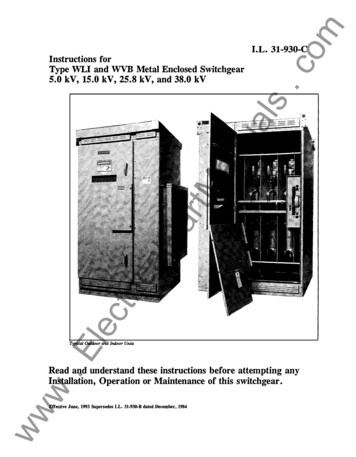
Installation andMaintenance ManualLow Voltage SwitchgearMaxSG
Low Voltage SwitchgearMaxSG Installation andMaintenance ManualTaCo blent ofentsIndex1. Introduction to MaxSG Low Voltage Switchgear. 12. Important Safety Notes and Warnings. 23. Receiving and Handling . 34. Site Preparation. 45. Indoor/Outdoor Installation. 56. Outdoor Installation. 117. Testing and Final Inspection. 138. Placing Switchgear into Service. 169. Standard Construction. 1710. Maintenance. 1811. Warranties. 20Low Voltage Products & SystemsABB Inc. 888-385-1221 www.abb-control.com LV082 [1SXU 900 082 M0201] 5/07
Table of ContentsIntroduction to MaxSG Low Voltage Switchgear.1General Instructions.1Scope of Instructions.1Important Safety Notes and Warnings.2Safety Notations.2Receiving and Handling.3Receiving.3Handling.3Storage.3Site /Outdoor Installation.5General.5Moving by Jacks and Rollers.5Raising by Slings.6Removal of Shipping Base.7Circuit Breaker Overhead Lifting Device.7Installation.7Operation of the Circuit Breaker OverheadLifting Device.9Unit Substations.9Connections.10Installation of Bus Bar Connections BetweenGroups.10Connection to Ground Bus Bar.10Connection to Neutral Bar (Optional).10Connection to Control Source.10IILV082 [1SXU 900 082 M0201] 5/07Outdoor Installation.11General.11Bus Duct Flange.11Joining the Shipping Splits.11Testing and Final Inspection.13Testing.13Control Circuit Checkout.13Final Inspection.14Typical SACE Emax Circuit Diagram.15Placing Switchgear into Service.16Safety Precautions.16Energizing the Main Bus.16Standard Construction.17Standard Color.17Galvalume.17Support and Bus Bars.17Ground Bus and Contacts.17Control Wires.17SACE Emax Circuit breakers.17Maintenance.18General.18Semi-Annual Inspection.18Annual Inspection.1818 to 36 Month Inspection.1910 Year Maximum Inspection.19Suspect Joint – Maintenance.19Care of Finish.19Renewal Parts.19Warranties. 20Disclaimer of Warranties and Limitation of Liability.20Low Voltage Products & SystemsABB Inc. 888-385-1221 www.abb-control.com
1IntroductionMaxSG Low VoltageSwitchgearGeneral InstructionsRead these instructions carefully before installation anduse as a guide during installation and initial operation.File these instructions with other instruction books,drawings and descriptive data of the switchgear. Keepthis book available for the installation, operation, andmaintenance of this equipment. Use of the instructionwill facilitate proper maintenance of the equipment, andprolong its useful life.Information on particular installations appears in thefollowing: Bills of Materials that list electrical devices andequipment Front view showing layout of relays, instruments andcircuit breakers Single line drawings showing power connections Floor plan showing available space for power andcontrol conduitsScope Of Instructions Special construction detailsThe instructions are general in nature. They coverrequirements for installation, setup, checkout andmaintenance as applied to ABB MaxSG Low VoltageSwitchgear. These instructions do not attempt to coverall variations and combinations of equipment andinstallations. Elementary and schematic diagramsLow Voltage Products & SystemsABB Inc. 888-385-1221 www.abb-control.com Connection diagrams LV082 [1SXU 900 082 M0201] 5/07
2Important Safety Notes and WarningsSwitchgear operation depends on proper handling,installation, and maintenance. Neglecting fundamentalrequirements may lead to personal injury, failure of theswitchgear, and property damage.Safety as described in this instruction book involves twoconditions: Personal injury Product or property damageSee important "Disclaimer of warranties andlimitation of liability" on page 11.2.Safety NotationsSafety notations alert personnel to possible death, injury,or property damage situations. The safety notationsappear before the step in which the condition applies.The four hazard levels are:Personnel installing, operating, or maintaining thisequipment must have thorough knowledge of allapplicable local, regional, industry, governmental, andOSHA safety procedures as well as commonly acceptedsafe working practices. Personnel working in, on oraround this equipment must also exhibit common senseand good judgment regarding the potential hazardsfor themselves and other personnel in the area. Theseinstructions are intended for use by fully qualifiedpersonnel and are not a substitute for adequate training,experience, and supervision.Should clarification or additional information be required,refer the matter to your ABB Company sales office. Whencommunicating with ABB regarding the product coveredby this manual, always reference the ABB assigned ShopOrder (S.O.) number or Circuit Breaker Serial Number.DANGER"Danger" indicates a hazardous situation that has a high probabilityof death or severe injury and substantial property damage.WARNING"WARNING" indicates a hazardous situation that has some probabilityof death or severe injury and substantial property damage.CAUTION"CAUTION" indicates a hazardous situation that may result inminor or moderate injury and/or property damage."NOTICE" Indicates a statement of company policy as it relatesdirectly to the safety of personnel or protection of property. LV082 [1SXU 900 082 M0201] 5/07Low Voltage Products & SystemsABB Inc. 888-385-1221 www.abb-control.com
3Receiving and HandlingReceivingStorageBefore shipment, the switchgear is inspected andmarked with its number and position. The factory shipscircuit breakers separately.Leave the equipment on the shipping base.Upon receipt of the switchgear, examine the shipment fordamage or loss. Check the contents against the packinglist before discarding any packing material. Notify ABBand the carrier at once of any discrepancies. If there isdamage from improper handling, file a claim for damagesat once with the carrier and notify ABB.Note: ABB standard shipments are "FOB factory."ABB is not responsible for damage, after delivery ofthe equipment to the carrier.HandlingFor structural integrity, all doors and panels must be in place andsecurely fastened before moving the equipment.Do not move or transport the switchgear with the circuit breakersinstalled.Store all equipment indoors in a well ventilated area.The storage building should have a well-drained pavedfloor. The temperature should be above 60 F (16 C). Theair should be dry (50% maximum humidity).The sections ship wrapped in plastic for protectionduring shipment only. Remove the plastic wrap afterplacing into storage. Cover with heavy wrapping paperor other moisture barrier. Do not use materials that wouldtrap moisture inside the unit. Do not cover louvered orfiltered openings.When storing for a long period of time or in high-humidity,use heaters to keep the interior dry. Bring the powerfor the heaters to the load terminals of the device thatcontrols the heater circuits.Note: The device must remain open when using aseparate power source.Store circuit breakers upright in their original shippingcarton. Do not stack. Do not store circuit breakers in theswitchgear.Before energizing the heaters, remove all the packing materialsfrom the switchgear. Open the circuit breaker or cutout devicethat controls the heaters when using a separate power source.Low Voltage Products & SystemsABB Inc. 888-385-1221 www.abb-control.com LV082 [1SXU 900 082 M0201] 5/07
4Site PreparationGeneralFoundationBefore installing, consult all drawings furnished for theparticular order. The drawings show top and front viewsof the switchgear, primary and secondary connectiondiagrams, and Bills of Materials. Study these drawingsand the following recommendations before preparing thesite plan drawings.The factory supplies floor plan drawings for eachinstallation. The concrete floor must be straight and levelwithin 1/4 inch over the entire length of the line-up.LocationLocate the switchgear in accordance with localregulations. Clearances at the front should allow theinstallation and removal of the circuit breakers. Allowenough rear clearance to open the rear doors. Providerear access for making connections before startup andfor periodic inspections. The recommended minimumclearances appear on the drawings. LV082 [1SXU 900 082 M0201] 5/07The design of the floor may include iron sills in theconcrete. The sills must be straight and level within 1/4inch over their full length, and correctly spaced. Bolt tiesbetween the sills and shim the lower flange of each sill toproper height.Install power and secondary (control) conduits beforemoving the switchgear to the site. Available space for theconduits appears on the floor plans supplied with theswitchgear. Conduits should not extend more than one (1)inch above the station floor level. Plug conduit openingsbefore pouring concrete.Low Voltage Products & SystemsABB Inc. 888-385-1221 www.abb-control.com
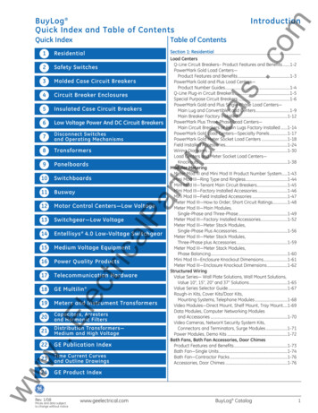
Indoor/Outdoor InstallationGeneralMaxSG metal-enclosed switchgear ships in sections.Sections ship on heavy timber bases or on optionalthrowaway steel bases. See Figure 1.52. Raise the unit enough to position a roller under theshipping base. Repeat the operation at the otherend. See Figure 3.Figure 1. Sections and the shipping base.Unload the switchgear as close to the installation site aspossible. Raise the switchgear with jacks and move onrollers with the shipping bases in place or with an overheadhoist and spreader bar. (See pages 5.2 and 5.3).Moving Jacks And RollersUse of forklift trucks for jacking or placing the jacks other thanas described may result in stress distortions and irreparabledamage to the switchgear.Do not remove the shipping bases until the units are set In place.Moving the units without the shipping base will cause irreparabledamage and a hazardous condition.In many locations the best way of moving the switchgearis with jacks and rollers.Figure 3. Raise the unit enough to position a roller under theshipping base.3. Push the switchgear toward its final position, whileanother person puts a third roller under the forwardend. Keep moving a roller from the rear to the frontuntil the unit is in place.4. For lateral moving, raise the units by jacks asdescribed in step 1. Place the rollers laterally withsteel channels (not furnished) on the rollers. SeeFigures 4 and 5. Carefully push the unit onto a thirdroller and move a roller from the rear to the front untilthe unit is in place.1. Do not remove the shipping base. Move the unitnear the site. Raise the unit by jacks placed underthe front and rear corners. See Figure 2. Note: Somesections are on throw away steel bases.Figure 4. Position rails on rollers as shown for lateral moving.Figure 2. Position jacks under the front and rear corners, insidethe shipping base.Low Voltage Products & SystemsABB Inc. 888-385-1221 www.abb-control.com LV082 [1SXU 900 082 M0201] 5/07
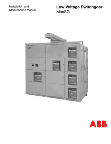
5Indoor/Outdoor InstallationRaising By Slings1. For raising and moving the switchgear with slings,use the shipping bases as shown in Figure 6. Eachsection has its own shipping base, which providesa large hole at each end for attaching a sling andspreader bar assembly.Attachslings inthe fourholes of theshippingbase.Figure 4. Position rails on rollers as shown for lateral moving.Figure 6. End view showing lifting eye.2. Use a spreader bar to keep the legs of the slingvertical.3. Lift and move the switchgear to its final place. Oncethe unit is set in place, remove the shipping base.Figure 5. Carefully push the unit onto a third roller.5. Locate the units in their final position. Raise the unitsto clear the rollers and channels. LV082 [1SXU 900 082 M0201] 5/07Low Voltage Products & SystemsABB Inc. 888-385-1221 www.abb-control.com
5Indoor/Outdoor InstallationRemoval of Shipping BaseInstallationOnce the units are in their final place, remove the shippingbases.1. Open the switchgear doors. Remove the bolts holdingthe shipping bases to the switchgear. Secure alldoors and panels before going to the next step.2. Raise the switchgear to a height that allows removalof the base. Use four jacks for this operation to keepthe units uniformly level and prevent distortion.1. Remove the Carriage-Stop from one end of thelineup.RemoveCarriageStop.3. Remove and discard the shipping bases.4. Select four pieces of wood thick enough to permitremoval of the jack after lowering. Place one at eachcorner. Slowly lower one side of the switchgear until itrests on the wood. Repeat this process on the otherside. The switchgear should now be sitting on the fourpieces of wood.5. Use a crowbar to lift each corner and remove the fourpieces of wood.Boltsholding theswitchgear tothe shippingbase.Figure 8. Remove the Carriage Stop and End Panel.2. Loosen all rails for the overhead lift device. Mount theLocator Plates as shown in Figure 9. Note that theplates have round bosses that mate with holes in therails. Adjust the rails as required to loosely secure thelocator plates in place with the bosses in their matingholes. After mating all Locator Plates in place with therails, secure the locator plates and the rails.Use theseholes(front andrear) whenanchoring theunit in place.Figure 7. View of front mounting provisions.Circuit Breaker Overhead Lifting DeviceFigure 9. Mount Location Plate behind the rail.There is available a traveling overhead lifting device inthe MaxSG switchgear for ease of handling SACE Emaxcircuit breakers. The front section of the switchgearprovides support for the lifting device. The hoist travelsthe full width of the switchgear. The breaker lifts from thefloor or from a completely withdrawn circuit breaker cradlewith a lifting yoke. A worm driven mechanism and wirerope, operated by a removable hand crank provide liftingpower. Although the driving mechanism allows for easyhand operation, the weight of the circuit breaker cannotaccidentally move the mechanism. See the correspondingABB drawing for detailed operating instructions.Low Voltage Products & SystemsABB Inc. 888-385-1221 www.abb-control.com LV082 [1SXU 900 082 M0201] 5/07
5Indoor/Outdoor Installation4. Lift the Overhead lift device up to the rails on theframe.Figure 10. Secure plates and rails for a smooth and continuoustransition between sections.3. Position Overhead Lift device on the tines of forklift.Figure 12. Lift the Overhead lift device up to the rails on the frameAdjust theupper rearwheel tominimizeverticalmovement.Figure 11. Position Overhead Lift Device on tines of fork lift. LV082 [1SXU 900 082 M0201] 5/07Figure 13. Align wheels on the front rail and behind the rear rail asshown.Low Voltage Products & SystemsABB Inc. 888-385-1221 www.abb-control.com
5Indoor/Outdoor Installation5. Push the Overhead lift device off the forklift onto therails.Operation of the Circuit Breaker OverheadLifting DeviceObserve the following requirements when operating thecircuit breaker lifting device.1. The wheels must be properly set on track.2. Do not depend upon the drum attachment tosupport full weight. Allow 4-5 wraps of wire rope toremain on the drum.3. Prevent snarling, kinking or knotting the wire rope.4. Lift only circuit breakers.5. Do not alter the lifting device or the circuit breakerlifting yoke.6. Never walk or stand under a circuit breakersuspended by wire rope.Figure 14. Push the Overhead Lift Device onto the rails.6. Test the continuous movement of the Overhead liftdevice and reinstall the Carriage Stop bracket.7. Do not leave a circuit breaker suspended on the wirerope.Unit SubstationsUnit substations are power transformers with primaryand secondary switchgear. They are field assembledto make a complete unit. Install the transformersand switches next to the switchgear as shown oncoordination drawings.In multi-unit substations, physically identicaltransformers may have disconnect switches that arekey interlocked with secondary breakers. Group thedisconnect switches, transformers and switchgearsections by their key interlock. The interlock sequencedepends upon having the locks on the switch andbreaker operated by the same key.Figure 15. Install the item removed in Step 1 OPERATION OF THECIRCUIT BREAKER OVERHEAD LIFTING DEVICELow Voltage Products & SystemsABB Inc. 888-385-1221 www.abb-control.comNote: Avoid unnecessary rework by checking the keynumbers before moving each piece of equipmentinto its final position. LV082 [1SXU 900 082 M0201] 5/07
5Indoor/Outdoor InstallationConnectionsWARNINGBefore making primary source connections verify that the primary cablesare de-energized.Switchgear are normally shipped in two or three separatesections (shipment sections) according to the lengthof the switchgear. The factory splits the buses forshipment. Control wiring end at the shipping split, in thecase of any interconnection between shipment sectionsinterconnection boards are left too.Bolt tightly the separate units together. See Table 1.Reconnect the bus and control wiring at the shippingsplits. To avoid mistakes, follow the connection diagramwhen replacing control wiring.Table 1Torque Values for Low Voltage Equipment HardwareBolt e all internal connections. Make the externalconnections to control power sources and circuits, tosecondary and potential circuits, feeders, and powersources to ground.Note: After completing all connections to secondary(control) circuits, follow these circuits and removetemporary connections from current transformersecondaries.The outgoing connections are carried out in the terminalsdestined for each principal and derivate switch, removethe subsequent screwed covers for reaching theterminals and tighten the cables.Make the feeders connections after all other connectionsare complete. Be sure to make the right phasesconnections specified in standards for each equipment.The contact surfaces of the bus at bolted joints areplated. Clean contact surfaces with a clean cloth andan OSHA approved solvent. Limit the use of solventsto removing grease and contamination from primaryconductors and insulation, and from unpainted metallicsurfaces. Bolt the bus together. Conductivity of a jointdepends upon the pressure or torque applied. See Table 1.Note: Take care not to remove plating.Connection to Ground Bus BarThe factory bolts the ground bus bars to each frame.Connect the ground bus bars to the station ground bymeans of a cable or bus of larger gage than the housingground bus.Do not run cable or bus in conduit. The cable or busshould take the most direct path to station ground.Connection to Neutral Bar (Optional)This neutral bar runs along the subsequent part of theswitchboard. It is supported by the metallic structure ofthe switchboard and insulated form it through insulators.This neutral bar runs parallel to the ground bus bar.Connection to Control SourceThe control source wiring of the switchboard shouldcome from a section that will not cause minimal voltagefall, especially when the feeder source is to far from theswitchboard.Be careful with the phases sequence and the number ofterminals when connecting.The factory wires the secondary and control connectionsusing the connection diagram for installation. Terminalboards for the easy connection of the client provide theoutgoing secondary and control connections.Once the switchboard is in its final location, al the controlexternal circuits and the splice board connections will beconnected.Installation of Bus Bar Connections BetweenGroupsThe factory assembles the main bus bar in each section.The splices at the shipping splits are unbolted forshipment. Refer to the Connection Diagram.Do not use alcohols or freons. Limit the use of solvents toremoving grease and contamination from primary conductors,insulation, and unpainted metallic surfaces. Use an OSHAapproved, non-flammable solvent with a threshold limit of300 PPM or higher in accordance with local regulations. Usesolvents in well-ventilated areas.10LV082 [1SXU 900 082 M0201] 5/07Low Voltage Products & SystemsABB Inc. 888-385-1221 www.abb-control.com
6Outdoor InstallationGeneralOutdoor and indoor installations are similar. Outdoor unitsare on permanent bases. Use jacks to raise the units forpositioning the rollers.The bases have lifting holes in each end for overheadlifts. Use spreader bars with slings attached in the liftingholes. This prevents damage to the unit tops.Bus Duct FlangeMount the bus duct flange when installing the switchgear.1. Place the gasket between the roof and the flange.Use the adhesive as a binder between each of theparts.2. Cement the gasket to the roof.3. Cement the flange over the gasket.Figure 16. Install gasket material between shipping splits beforebolting together.4. Bolt the flange to the structure.5. Apply a bead of sealer to the exposed edges of thegasket.Joining the Shipping SplitsFor installations of more than three shipping splits,carefully locate the center section in its final position andadd the remaining units on either end.Locate the shipping splits together in their final locationrelative to the floor anchor arrangement if used. It may bedifficult to make position adjustments without damage,after bolting the units together.Allow space to install gasket material supplied with theunit if not already installed.1. Apply gasket material as shown on the Gasketapplication drawings. See Figure 16 and Figure 18.Figure 17. Bolt shipping splits together.2. Loosely bolt the sides of the unit together. See Figure17.3. Install the angle supplied to the roof seam andsecure. See Figure 19 and Figure 20.4 Tighten the bolts in the sides of the units. Payattention to the relative position of the units to thefloor anchor arrangement if used.5. Apply sealant where required as shown in Figure 21.Low Voltage Products & SystemsABB Inc. 888-385-1221 www.abb-control.com11LV082 [1SXU 900 082 M0201] 5/07
6Outdoor InstallationFigure 18. Install gasket material between shipping splits.Figure 20. Tighten the shipping split angle evenly.Apply sealantall aroundFigure 19. Loosely install the shipping split angle as shown.Figure 21. Sealant when required.12LV082 [1SXU 900 082 M0201] 5/07Low Voltage Products & SystemsABB Inc. 888-385-1221 www.abb-control.com
Testing and Final Inspection7Control Circuit CheckoutTestingDANGERDANGERDisconnect the primary power source during testing.Do not exceed the listed voltages for the voltage class of theequipment under test.Disconnect the shunt-connected coils such as potential transformers.Do not test solid state sensors or relays with high voltage. Disconnectsolid state sensors and relays before applying voltage.With the switchgear erected, assembled, andconnected, do the following:1. Remove packing and shipping materials.2. Make sure that all internal parts are clean and dry. Ifmoisture is present, dry with moving air and heat.3. Remove shipping blocks from relays.4. To check for damaged insulation, apply potentialtests to the primary bus. Potential tests should beconducted phase-to-phase and phase-to-ground.60 HZ, RMSWITHSTAND VOLTAGES(PRIMARY CIRCUITS)(1 MINUTE)Rated Voltage240v, 480v, 600vFactory Test2200 voltsDCWITHSTAND1Field Test1650 voltsField Test2300 volts1 The Column headed DC WITHSTAND is a reference for thoseusing DC tests to verify the integrity of connected switchgear. Itrepresents values believed to be appropriate and approximatelyequivalent to the corresponding power frequency withstandtest values specified for each voltage class of switchgear. Thepresence of this column in no way implies any requirements for aDC withstand test on AC equipment. Also, it does not imply thata DC withstand test is an acceptable alternative to ANSI C37.20for design, production, or conformance tests. When making DCtests, raise the voltage to the test value in discrete steps andhold for one (1) minute.5. With the main circuit dead, check the continuityof all circuits after installing the circuit breakers.Energize the control source and operate theequipment. Indicating instruments verify thecontinuity of current transformer circuits afterenergizing the main circuit.The breaker or cutout device of the local control power circuit mustremain open when using a separate control power source.The preferred method to check the control circuit is tofurnish a separate temporary source of control powerof the required control voltage rating. The temporarysource must have a properly coordinated backupprotective device in the circuit. Set the device to clearfaults that might occur. Initially all circuit breakers shouldbe in the DISCONNECT position and the main circuitde-energized. When AC control power is from controlpower transformers in the switchgear, remove all fusesin the transformer circuits. On electrically operatedcircuit breakers, discharge the springs and the motordisconnect-switch should be in the OFF position.DANGEROPEN the circuit breaker before racking.6. Rack drawout breakers to the DISCONNECTposition.7. Open all normal control power source disconnects, ifsupplied.8. Check each control switch or push-button. Makesure that it is in the OPEN position.9. Connect a temporary control power source to thecircuit load terminals in the switchgear. Energizethe control circuit from the temporary control powersource.10. Rack one circuit breaker into the TEST position.When the on-off switch is in the ON position, thecharging of the closing springs of an electricallyoperated circuit breaker indicates connection to thecontrol power.11. Rack the remaining circuit breakers into the TESTposition, one at a time.12. Test all electrically and manually operated breakersfor closing and tripping, while they are in the TESTposition. Use the optional test set available with thetrip unit for testing solid state tripping.13. De-energize the control circuit. If AC control poweris from transformers in the switchgear, removethe temporary separate source of control power.Reinstall all fuses in the transformer circuit.14. Set all relays, regulators, and other devices forproper operation of loads. The factory does not setthe relays.Low Voltage Products & SystemsABB Inc. 888-385-1221 www.abb-control.com13LV082 [1SXU 900 082 M0201] 5/07
7Testing and Final Inspection15. Remove shorting screws from the terminal blocksin the current transformer circuits. See Figure 22on page
Raising By Slings 1. For raising and moving the switchgear with slings, use the shipping bases as shown in Figure 6. Each section has its own shipping base, which provides a large hole at each end for attaching a sling and spreader bar assembly. Attach slings in the four holes of the shipping base. Figure 6. End view showing lifting eye. 2.