Transcription
DCS F/A-18C HORNETEarly Access Guide
DCS [F/A-18C]ContentsHEALTH WARNING!. 6INSTALLATION AND LAUNCH. 7GAME PROBLEMS . 7USEFUL LINKS . 7CONFIGURE YOUR GAME. 8PLAY A MISSION . 12FLIGHT CONTROL . 13F/A-18C HORNET COCKPIT OVERVIEW . 15Left Instrument Panel . 17Center Instrument Panel . 21Right Instrument Panel . 25Left Vertical Panel . 27Left Console . 29Right Vertical Panel. 31Right Console . 33Control Stick . 36Throttles . 37DDI and AMPCD Pages . 38Support (SUPT) Pages. 38Tactical (TAC) . 46HEAD UP DISPLAY. 51PROCEDURES . 53Cold Start . 53Taxi . 60Normal Takeoff. 61Landing. 62HORNET COMMUNICATION SYSTEM . 67How to Use the Radios . 67UFC Radio Functions . 68HORNET MASTER MODES . 702
[F/A-18C] DCSHORNET NAVIGATION (NAV) . 70How to Navigate Using Waypoints. 70Waypoint Navigation . 74TACAN Navigation . 76DATA Option Sublevel . 79A/C (Aircraft) Sublevel . 79WYPT (Waypoint) Sublevel. 80TCN (TACAN) Sublevel . 80Automatic Direction Finder (ADF) Navigation . 81How to Navigate Using ADF Beacons . 81Additional HSI Symbology . 82Setting a Course . 83Autopilot Relief Modes . 83HORNET AIR-TO-GROUND (A/G) . 85Air-to-Ground Stores Management System (SMS) Bombing Page . 85A/G Stores Programming . 87Air-to-Ground Bombing HUD . 89Continuously Computed Impact Point (CCIP) Bombing HUD . 89How to Bomb Using CCIP Mode. 90Automatic (AUTO) Bombing HUD . 91Manual (MAN) Bombing HUD . 97Air-to-Ground Gun and Rockets . 99How to Use A/G Guns . 99How to Use Rockets . 99A/G Gun SMS Page . 100Rockets SMS Page . 101A/G Gun and Rocket HUD . 102HORNET AIR-TO-AIR (A/A) . 105Air-to-Air RADAR . 106Basic Air-to-Air RADAR Information . 106Range While Search (RWS) . 108How to Use RADAR in Beyond Visual Range Mode . 1083
DCS [F/A-18C]Air-to-Air RADAR HOTAS Controls .111Range While Search (RWS) DATA .114Air Combat Maneuvering (ACM) Modes .115M61A2 Gun, Air-to-Air Mode (A/A GUNS) .117How to Use the Gun Summary .117A/A GUNS SMS Page .117A/A GUNS HUD.119Radar Not Tracking Mode .119Radar Tracking Mode .122AIM-9 Sidewinder Air-to-Air Missile .127How to Use the AIM-9 Summary .127IR Cool Switch .127AIM-9 on the SMS Page .128AIM-9 HUD .129AIM-7 Sparrow Air-to-Air Missile .135How to Use the AIM-7 Summary .135AIM-7 SMS Page .136AIM-7, No RADAR Tracking .137AIM-7, RADAR Tracking .138AIM-7 with L&S Target .140HORNET DEFENSIVE SYSTEMS .143Integrated Countermeasures Control Panel (ICMCP) .144EW Page .146Azimuth Indicator .149Right Instrument Panel Warning / Advisory / Threat Display Panel .152BIT .153Control Indicator Panel .154HOTAS .1554
[F/A-18C] DCS5
DCS [F/A-18C]HEALTH WARNING!Please read before using this computer game or allowing your children to use it.A very small proportion of people may experience a seizure or loss of consciousness when exposed tocertain visual images, including flashing lights or light patterns that can occur in computer games.This may happen even with people who have no medical history of seizures, epilepsy, or“photosensitive epileptic seizures” while playing computer games.These seizures have a variety of symptoms, including light-headedness, dizziness, disorientation,blurred vision, eye or face twitching, loss of consciousness or awareness even if momentarily.Immediately stop playing and consult your doctor if you or your children experience any of the abovesymptoms.The risk of seizures can be reduced if the following precautions are taken, (as well as a generalhealth advice for playing computer games):Do not play when you are drowsy or tired.Play in a well-lit room.Rest for at least 10 minutes per hour when playing the computer game.6HEALTH WARNING!
[F/A-18C] DCSINSTALLATION AND LAUNCHYou will need to be logged into Windows with Administrator rights in order to install the game.After purchasing DCS: F/A-18C Hornet from our e-Shop, start DCS World. Select the Module Managericon at the top of the Main Menu. Upon selection, your Hornet will automatically install.DCS World is the PC simulation environment that the F/A-18C Hornet simulation operates within.When you run DCS World, you in turn launch DCS: F/A-18C Hornet.As part of DCS World, the Su-25T Frogfoot attack aircraft and TF-51 training aircraft are also includedfor free.After executing the DCS World icon on your desktop, the DCS World Main Menu page is opened.From the Main Menu, you can read DCS news, change your wallpaper by selecting either the F/A-18CHornet or Su-25T Frogfoot icons at the bottom of the page, or select any of the options along theright side of the page. To get started quickly, you can select Instant Action and play any of themissions listed in the F/A-18C Hornet tab.GAME PROBLEMSIf you encounter a problem, particularly with controls, we suggest you back up and then delete yourSaved Games\User Name\DCS\Config folder, which is created by DCS on your operating system driveat first launch. Restart the game and this folder will be rebuilt automatically with default settings,including all of the controller input profiles.If problems persist, we suggest consulting our online technical support forums athttp://forums.eagle.ru/forumdisplay.php?f 251USEFUL LINKSDCS : F/A-18C Hornet forum:https://forums.eagle.ru/forumdisplay.php?f 557DCS Wiki:http://en.wiki.eagle.ru/wiki/Main Page7
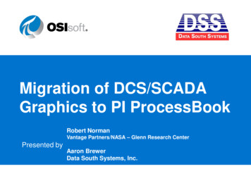
DCS [F/A-18C]CONFIGURE YOUR GAMEBefore jumping into the Hornet cockpit, the first thing we suggest is to configure your game. To doso, select the Options button at the top of the Main Menu screen. You can read a detailed descriptionof all Options in the DCS World Game Manual. For this Early Access Guide, we will just cover thebasics.OptionsFigure 1. DCS World Main MenuUpon selecting the Options screen, you will see seven tabs along the top of the page.8CONFIGURE YOUR GAME
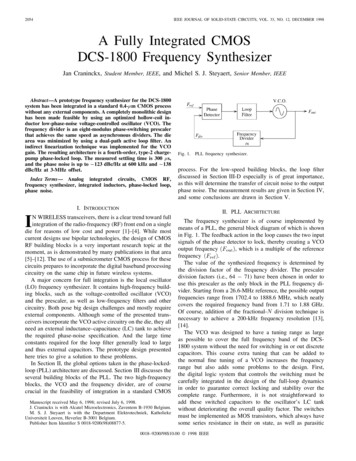
[F/A-18C] DCSFigure 2. DCS World OptionsSYSTEM. Configure your graphics options to best balance aesthetics with performance. You havePRESET options along the bottom of the page, but you can further adjust your graphics settings tobest suit your computer. If you have lower performance, we suggest selecting the Low PRESET andthen increase graphics options to find your best balance.CONTROLS. Set up your controls and functional bindings. Let’s take a closer look at this page:First, select the aircraft you wish to assign control inputs to by use of the Aircraft Selection dropdown. Next, along the left side of the screen are all the ACTIONS associated with the selected InputFunction drop down. To the right are all the detected input devices that have been detected toinclude keyboard, mouse, and any joysticks, throttles and rudder pedals.9
DCS [F/A-18C]Aircraft SelectionInput FunctionsAxis TuneFigure 3. Controls Configuration1.2.Aircraft Selection. From this drop-down menu, select F/A-18C Sim.Input Functions. This displays various categories of input functions, such as axis devices,views, cockpit functions, etc. To assign a function, double mouse-click in the box thatcorresponds to the desired input function and the input controller device. Once selected,press the button or move the axis of the device to assign it.3.a.4.10Example 1: if setting a pitch axis, first select AXIS COMMANDS from the InputFunctions drop down. Find the box where your Joystick input device and thePitch Action intersect, and double mouse-click in the box. In the ADDASSIGNMENT PANEL, move your joystick forward and back to assign the axis.Press OK when done.b. Example 2: if setting a keyboard of HOTAS command like cycle the landing gear,first select ALL as the Input Function category. Find the box where your inputdevice and the LANDING GEAR CONTROL HANDLE – UP/DOWN Action intersect,and double mouse-click in the box. In the ADD ASSIGNMENT PANEL, press thekeyboard or controller device button you wish to assign to the action. Press OKwhen done.Axis Tune. When assigning an axis (like X and Y axis for a joystick), you can use this subpage to assign a dead zone, response curve, and other tuning. This can be very useful ifyou find the aircraft overly sensitive to control.CONFIGURE YOUR GAME
[F/A-18C] DCSGAMEPLAY. This page primarily allows you to adjust the game to be as realistic or casual as youwant it to be. Choose from many difficulty settings like labels, tool tips, unlimited fuel and weapons,etc.AUDIO. Use this page to adjust the audio levels of the game. You also have the option to turn onand off different audio effects.MISC. This is a catch-all of features to further tune the game to your preference.VR. The VR tab allows you to enable support for the Oculus Rift and HTC Vive and adjust itsfunctionality. When using VR, be particularly aware of the Pixel Density setting as it can have adramatic effect on game performance.11
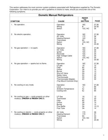
DCS [F/A-18C]PLAY A MISSIONNow that you have configured your game, let’s get to why you purchased DCS: F/A-18C, to fly somemissions! You have several options to fly a single-player mission.Figure 4. DCS World Main Menu1.2.3.4.5.6.INSTANT ACTION. Simple missions that place you in the task of your choice. We will beusing several of these in this Early Access Guide to test what you learn.CREATE FAST MISSION. Set various mission criteria to allow a mission to be created foryou.MISSION. More in-depth, stand-alone missions.CAMPAIGN. Linked missions to create a campaign narrative.MULTIPLAYER. Create your own or join an internet server.MISSION EDITOR. Use this very powerful Mission Editor to create your own missions.On the Main Menu page, you the options to fly the Hornet in an INSTANT ACTION mission, CREATEFAST MISSION, load a MISSION, play a Hornet CAMPAIGN when campaigns are available, or create amission in MISSION EDITOR. You also have the option to jump online and fly with others.Select the INSTANT ACTION from the right side of the screen. From here, you will be presented anumber of F/A-18C Hornet INSTANT ACTION missions to choose from.12PLAY A MISSION
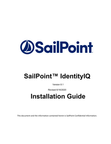
[F/A-18C] DCSTo get started, we suggest the FREE FLIGHT mission. Later on, you can also use these missions topractice starting up the aircraft, takeoffs, landings, navigation and sensor / weapon employment.FLIGHT CONTROLPrimary aircraft flight controls include the flight control stick, throttle, and rudder pedals. The stick isused to roll the aircraft left and right to perform turns and pitch the nose up and down to climb ordescend. The throttle is used to control engine power and resulting airspeed. The pedals are used toyaw the airplane left and right using the rudder (like a boat). Pedal use in flight is limited toeliminating sideslip and helping to coordinate smooth turns, but they are also used on the ground toturn the nose wheel when taxiing.To fly the aircraft to the right or left: roll the aircraft in the direction you wish to go and gently pullback on the stick. The greater you pull back on the stick, the faster your turn rate will be and themore speed you will lose.When flying from the cockpit, you can toggle the Controls Indicator display by pressing RCtrl Enter to see a visual reference of the positions of your flight controls.Left Throttle and Position IndicationRight Throttle and Position IndicationTrim Tab Position (mechanism used to reduce pressure on controlstick)Control Stick and Position IndicationPedals and Rudder Pedal IndicatorWheel Brake pressure IndicatorFigure 5: Controls Indicator displayMaximum Pitch Trim Deviation Indicator. Before takeoff, the pitch trim indicator (5) shall be setapproximately to a neutral positionIf you are flying only with a keyboard, the primary flight control keys will be: arrow keys to controlroll and pitch, Numpad and Numpad- to control throttle, and Z / X to control the rudderpedals. If you do have a joystick, it may be equipped with a throttle handle and/or a twist grip, whichwill allow you to control the rudder pedals.13
DCS [F/A-18C]Figure 6. Flight Key Commands14FLIGHT CONTROL
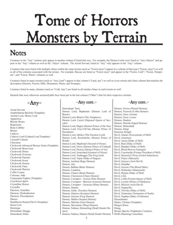
[F/A-18C] DCSF/A-18C HORNET COCKPIT OVERVIEWOnce in the cockpit, it’s best to have a general understanding of where the various controls arelocated. To help locate items more easily, we have broken the Hornet cockpit into eight primaryareas. In later sections of this Early Access Guide, we will reference these locations.Instant Action Mission Practice: Hornet Cold and DarkHornet Instant Action Mission: Hornet Cold and Dark. Use this mission to explore then cockpit andbecome familiar with its layout. To move your view: KeypadKeypadKeypadKeypadKeypadKeypad8: Up6: Right2: Down4: Left*: Zoom In/: Zoom OutPress pressing [LEFT ALT C] toggles mouse control between interacting with the cockpit andcontrolling your view.What follows is a summary description of cockpit functions included in this Early Access version thatare generally not described elsewhere in this document.15
DCS [F/A-18C]Left Instrument PanelCenter Instrument PanelRight Instrument PanelLeft Vertical PanelRight Vertical PanelThrottlesControl StickLeft ConsoleFigure 7. F/A-18C Cockpit Overview16F/A-18C HORNET COCKPIT OVERVIEWRight Console
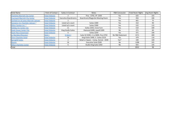
[F/A-18C] DCSLeft Instrument PanelMaster Caution LightLeft Warning/Caution AdvisoryLightsLeft Engine FireWarning/Extinguisher LightsFire Extinguisher PushbuttonLeft Digital Display Indicator(DDI)Master Mode ButtonsMaster Arm SwitchEmergency Jettison ButtonIntegrated Fuel / EngineIndicator (IFEI)Selective Jettison / LandingGear, and Flap Position LightsPanelFigure 8. Left Instrument Panel1.2.3.4.Left Digital Display Indicator (DDI). The left DDI is a 3-color display that provides desiredinformation to control various aircraft functions and displays. There are 20 pushbuttons on theDDI which are used to select the function and the mode for proper indicator display. Brightness Selector Knob. Placing this rotary knob to OFF prevents the DDI fromoperating. Placing the knob to NIGHT provides a lower brightness control range, and theDAY setting provides a more bright default setting. Brightness Control. This knob varies the intensity of the symbols and text. Contrast Control. This knob varies the contrast between symbology and the darkbackground on any level of brightness.Master Mode Buttons. These two buttons allow you to change between Air-to-Air (A/A) 1 andAir-to-Ground (A/G) 2 master modes. There are three master modes of operation: navigation(NAV), air-to-air (A/A), and air-to-ground (A/G). The controls, displays, and the avionic equipmentoperation are tailored as a function of the master mode you select.Master Arm Switch M . This switch controls the ability for weapons to be employed orjettisoned. Weapons can only be released when this switch is set to the ARM position.Emergency Jettison Button. The emergency jettison button, labeled EMERG JETT jettisonsstores from the parent bomb racks on external stores stations 2, 3, 5, 7 and 8. Holding the buttondown for 375 msec initiates jettison.17
DCS [F/A-18C]5.6.Selective Jettison / Landing Gear, and Flap Position Lights Panel. This panel has threeprimary functions; the top is used to selectively select stations to jettison and the bottom twoprovide landing gear and flaps status. Station Jettison Select Buttons. These buttons are labeled CTR (center), LI (leftinboard), RI (right inboard), LO (left outboard) and RO (right outboard). Pressing a buttonilluminates it and selects the weapon station for jettison. Selective jettison is performed bythe selective jettison knob in conjunction with the station jettison select buttons. Landing Gear Indications. There are three green landing gear position lights markedNOSE, LEFT and RIGHT. The lights indicate that the gear is down and locked, or that agear link is not locked. Flap Indications. A green light indicates the aircraft is within flight parameters for theflight control computer to adjust flap scheduling in accordance with the selected switchposition.oHALF. FLAP switch at HALF setting and airspeed below 250 knots.oFULL. FLAP switch at FULL setting and airspeed below 250 knots.oFLAPS. FLAP switch HALF or FULL settings and airspeed over 250 knots,abnormal flap condition (any flap is off or lacks hydraulic pressure), in spinrecovery mode, or GAIN switch in ORIDE position.Integrated Fuel / Engine Indicator (IFEI). The integrated fuel/engine indicator (IFEI) enginedisplay contains a left and right liquid crystal display for RPM (N2)%, TEMP (EGT) C, FF (fuelflow) PPH, NOZ (nozzle position)%, and OIL (oil pressure) psi. During engine starts withoutexternal electrical power, only RPM and TEMP are displayed by battery power until the APU comeson line. With the APU on line or external power, all engine data is displayed. Engine RPM. Displays engine N2 rpm from 0 to 100%. There is no RPM indication ofafterburner. Exhaust Gas Temperature (TEMP). Displays turbine exhaust gas temperature(EGT) from 0 to 1,999 C. Engine Fuel Flow (FF). Displays main engine fuel flow only (afterburner fuel flow isnot displayed). Range is 300 to 15000 Pounds Per Hour (PPH) with 100 pound perhour increments. The tens of units positions have fixed zeros. When fuel flow is lessthan 320 PPH, zero is displayed. Engine Nozzle Position (NOZ). Displays exhaust nozzle position from 0 to 100%open in 10% increments. Engine Oil Pressure (OIL). Displays engine oil pressure from 0 to 195 psi in 5 psiincrements.The IFEI fuel display window contains three digital counters to provide dynamic fuel quantityindications. The upper digital counter displays total aircraft fuel quantity (10-pound increments).The middle digital counter displays total internal fuel quantity (10-pound increments). A digitalcounter legend is displayed to the right of the upper and middle counters (T - total fuel, I - internalfuel). The lower digital counter displays the selected BINGO fuel quantity (100-pound increments).18F/A-18C HORNET COCKPIT OVERVIEW
[F/A-18C] DCSEngine RPMExhaust Gas TemperatureEngine Fuel FlowTotal FuelEngine Nozzle PositionTotal Internal FuelEngine Oil PressureFigure 9. Integrated Fuel / Engine Indicator (IFEI)7.8.9.Left Engine Fire Warning/Extinguisher Lights. If a fire is detected in the left engine,this indicator, marked FIRE, will be lit along with an "Engine Fire Left, Engine Fire Left"audio warning. This is a steady state, red light. To enable the fire bottle to discharge intothe selected engine/AMAD bay, the pilot must lift the guard over the FIRE warning lightand press the FIRE button. The button has two positions. Pushed in shuts off fuel flow tothe engine and arms the fire extinguisher and the READY light will illuminate. Pushing thisFIRE Warning button in once more toggles the button to the out position and the fuel valvewill open again for that engine and the READY light will turn off.Master Caution Light. A yellow MASTER CAUTION light, on the upper left part of theinstrument panel, comes on when any of the caution lights or caution displays come on.The MASTER CAUTION light goes out when it is pressed (reset). An audio tone is initiatedwhenever the MASTER CAUTION light comes on. This button is also used to “re-stack”caution and advisory notices.Left Warning/Caution Advisory Lights. The Left Warning/Caution Advisory Lightsprovide visual indications of normal aircraft operation and system malfunctions affectingsafe operation of the aircraft. A red warning light normally indicate a systems malfunctionthat could be a severe hazard to further flight, and may require immediate action. Yellowcaution lights and displays normally, but not always, indicate malfunctions that requireattention but not immediate action. After the malfunction has been corrected, warning andcaution lights and caution displays go out. Advisory lights and displays indicate safe ornormal conditions and supply information for routine purposes.19
DCS [F/A-18C] L BLEED. Will light when the Fire and Bleed Air Test Switch is pressed or bleed airleak or fire (600F degrees) has been detected in the left engine bleed air ducting. Ifilluminated, the left bleed valve is automatically closed. Will light when TEST A orTEST B switch is held or a bleed air leak or fire has been detected in the left engineducting. A "Bleed Air Left, Bleed Air Left" audio message will also sound. L BLD OFFcaution will be displayed on the LDDI. R BLEED. Will light when the Fire and Bleed Air Test Switch is pressed or bleed airleak or fire (600F degrees) has been detected in the right engine bleed air ducting. Ifilluminated, the right bleed valve is automatically closed. Will light when TEST A orTEST B switch is held or a bleed air leak or fire has been detected in the right engineducting. A "Bleed Air Right, Bleed Air Right" audio message will also sound. R BLDOFF caution will be displayed on the LDDI. SPD BRK. Will light anytime the speed brake is not fully retracted. STBY. When ALQ-165 ECM mode switch is set to STBY on the ECM control panel, theSTBY light indicates that the EC
practice starting up the aircraft, takeoffs, landings, navigation and sensor / weapon employment. FLIGHT CONTROL Primary aircraft flight controls include the flight control stick, throttle, and rudder pedals. The stick is used to roll the aircraft left and right to perform turns and pitch t