Transcription
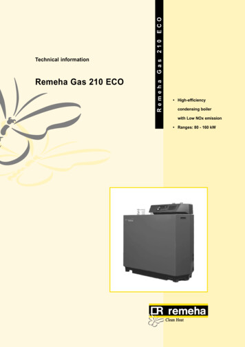
ECOGasRemeha Gas 210 ECORemeha210Technical information High-efficiencycondensing boilerwith Low NOx emission Ranges: 80 - 160 kW
CONTENTSPreface51General description of the boiler62Construction2.1 Boiler layout2.2 Operation principle7783Technical data and dimensions3.1 Dimensions3.2 Technical data3.3 Quotation specifications3.4 Optional Accessories991011114Efficiency information4.1 Annual efficiency4.2 Heat to water efficiency4.3 Standing losses121212125Application information126Control and safety equipment6.1 The instrument panel6.1.1 General6.1.2 Layout of the instrument panel6.1.3 Indication LED’s6.1.4 Manual override (hand/auto orforced modes ‘high’ and ‘low’)6.1.5 Display of values with more thantwo digits6.2 Flow diagram control system6.3 Operating mode (x [[)6.4 Shut-off mode (b XX)6.5 Setting mode user level (X [[)6.5.1 Flow temperature set point (!)6.5.2 Pump run on time (@)6.5.3 Boiler control setting ng mode service level (only for thequalified service engineer) (X [[)216.6.1 Low fire start point ( )226.6.2 Boiler output to indicate high fire(%)226.6.3 Maximum output (6)226.6.4 Forced part load and running time(& en *)226.6.5 Cycling prevention delay-time (() 226.6.6 Start and end point for analog signal(a and B)226.6.7 PWM pump position (C and D)226.6.8 t from control stop point to startpoint (E)226.6.9 Maximum flue gas temperature (F) 226.6.10 High limit temperature set point (G) 226.6.11 Modulation start point T (H)226.6.12 Minimum water pressure (I)236.6.13 Adjustments options/accessories(J)236.6.14 Base point internal compensationslope (L)236.6.15 Boiler type (P)23Read-out mode (X [[)23Failure mode (x [[) (service level)25Counter mode (1, , and .)(service level)256.9.1 Hours Run256.9.2 Successful ignition attempts256.9.3 Total start attempts26Installation instructions7.1 General7.2 Delivery, positioning and support surface7.3 Flue gas discharge and air supply7.3.1 General7.3.2 Classification due to dischargingflue gases7.3.3 Material and installation7.3.4 Single boiler conventional flue7.3.5 Single boiler, room sealed flue7.3.6 Different pressure zones7.3.7 Cascade flue systems7.4 Installation details7.4.1 Condensate discharge7.4.2 Water treatment7.4.3 Safety valve7.4.4 Water circulation7.5 Multiple installation2727272929292930303131313131323233
RemehaGas 210 ECO8Electrical installation358.1 General358.2 Electrical specifications358.2.1 Power supply358.2.2 Automatic Controls358.2.3 Fuse specification358.2.4 Boiler temperature control358.2.5 Low water protection(flow and content)358.2.6 High limit protection358.2.7 Differential air pressure switch (LD2) 358.3 Electrical connections358.4 Boiler control378.5 Safety interlocks398.5.1 Shut-down interlock398.5.2 Lock-out interlock398.6 Remaining outputs398.6.1 Analog output398.6.2 Indicating module No.1408.7 Options/accessories408.7.1 Provision for thermostat pocket408.7.2 Water pressure sensor408.7.3 Differential pressure sensor408.7.4 Gas valve proving(only for 120 and 160 kW boilers)408.7.5 Minimum gas pressure switch418.7.6 Indicating module No.2418.8 Remaining connections418.8.1 System pump418.8.2 Frost protection419Commissioning9.1 Initial lighting9.2 Shut-down10 Fault-finding10.1 General10.2 Overview malfunctions (locking)11 Inspection and servicing / maintenanceinstructions11.1 General11.2 Annual inspection11.2.1 Check combustion characteristics11.2.2 Cleaning the IMS-system11.2.3 Cleaning the siphon11.2.4 Check the adjustment of theignition probe11.2.5 Check the water pressure11.3 Maintenance4424243444444484848484848484848
PREFACERead these instructions carefully before putting the boiler into operation, familiarise yourself with its controlfunctions, operation and strictly observe the instructionsgiven. Failure to do so may invalidate warranty or prevent the boiler from operating.If you have any questions, or if you need more information about specific subjects relating to this boiler, or itsinstallation please do not hesitate to contact us.The data published in these technical instructions isbased on the latest information (at date of publication)and may be subject to revisions.We reserve the right to continuous development in bothdesign and manufacture, therefore any changes to thetechnology employed may not be retrospective nor maywe be obliged to adjust earlier supplies accordingly.The installation and commissioning of the boiler mustbe carried out by a competent Engineer, with the relevant certification i.e.: CORGI, ACOPS, IEE regs. Oncompletion a copy of the commissioning sheet should bereturned to Broag Ltd. for record purposes.Fig. 01 Artist impression Gas 210 ECO5
RemehaGas 210 ECO1GENERAL DESCRIPTION OF THE BOILERAn intelligent, advanced boiler control ('abc ') continuously monitors the boiler conditions, varying the heatoutput to suit the system load. The control is able toreact to external "negative" influences in the rest ofthe system (flow rates, air / gas supply problems) maintaining boiler output for as long as possible withoutresorting to a lock out condition. At worst the boilerwill reduce its output and/or shut down (shut off mode)awaiting the "negative" conditions to to return to normalbefore re-starting.The 'abc ' control cannot override the standard flamesafety controls.Every Remeha Gas 210 ECO is checked followingassembly by means of a test computer to ensure itsproper operation.The boiler meets the requirements of the EC regulationsof the directives:- 90/396/EEC Gas appliances directive- 92/42/EEC Efficiency directive- 89/336/EEC E.M.C. directiveand comply with the following requirements:- 73/23/EEC Electrical low voltage directive.- 89/392/EEC Machinery directive.The Remeha Gas 210 ECO boiler is a pre-assembled,free standing, gas fired, high efficiency condensing boiler.The sectional cast aluminium heat exchanger and othermajor components are contained within a sealed airbox. This forms the main boiler casing with a removablefront section for maintenance purposes. All electrical andelectronic controls are contained within the instrumentpanel mounted on top of the boiler.The flue gas outlet, combustion air inlet, flow, return andgas connections are located on the top of the boiler witha condensate connection at low level on the right handside.The boiler is suitable for room sealed or open flue applications and has been designed for central heating andindirect hot water production at working pressures notexceeding 6 bar. It must be installed on a fully pumpedsystem and is suitable for use on both sealed and openvented installations (minimum operating pressure openvented 0.3 bar).The pre-mix gas burner (NG only) with its gas/air ratiocontrol system ensures clean, trouble free operation withhigher than average efficiencies 109% (NCV) in thecondensing mode combined with ultra low NOx andminimum CO emissions. The standard control packageallows actual and set values to be read and adjustedon the built in digital display which also provides normaloperating and fault code indication.CE Reference number : 0063 BL 3264.6
2CONSTRUCTION2.1 Boiler 71828Fig. 02 Cut away view of Remeha Gas 210 ECO (160 kW model 14.15.16.17.18.19.20.21.air supplyflue gas outletcombustion test point (O2/CO2)sealed air boxdifferential air pressure switch (LD2)IMS gas-air ratio controlair supply fanpre-mix, fibre faced burnercombined ignition/ionisation probesight glassgas combi-block (with governor)cast aluminium, sectional heat exchangertemperature sensor - flowtemperature sensor - returntemperature sensor - heat exchangertemperature sensor - flue gas22.23.24.25.26.27.28.29.7drain pan (condensate)condensate connectionheat exchanger inspection hatchinstrument panelfacility for incorporating a rematic weathercompensator (optional)boiler setting keysread-out display and reset keyon/off switchgas connectionflow connectionreturn connectiondrain cock and optional second return connection(when fitted)connection for optional thermostat pocket(for use with external sequence control)
RemehaGas 210 ECO2.2 Operation principleCombustion air is drawn into the closed air box throughthe air inlet from the plant room (open flued) or fromoutside via the eccentric flue system (room sealed) byan air supply fan.On the inlet side of the fan is a specially designedIMS (Integrated Mixing System) gas / air ratio controlunit which takes gas from the combi-block and mixesit in the correct proportions with the incoming air. Thismechanical mixing system ensures the correct mixture isdelivered to the pre-mix burner at all times.Depending on demand (under the dictates of flow/returnsensor and other external/internal control inputs) the‘abc ’ system determines the boiler output, which directlycontrols the the volume of mixed gas and air to thepremix burner. This mixture is initially ignited by thecombined ignition/ionisation probe which monitors thestate of the flame. Should the flame be unstable or notignite within the pre-set safety time cycle the controls will(after 5 attempts) shut the boiler down requiring manualintervention to reset the boiler. The digital display willindicate a flashing fault code confirming the reason forthe failure.The products of combustion in the form of hot flue gasesare forced through the heat exchanger transfering theirheat to the system water (the flue gas temperature isreduced to approximately 5 C above the temperatureof the system return water) then discharged via thecondensate collector, vertically through the 150 mm connection to atmosphere.Because of the low flue gas exit temperature there willbe a vapour cloud formed at the flue gas terminal - thisis not smoke, simply water vapour formed during thecombustion process.If the controls allow the flow and therefore return temperature to fall below dew point (55 C) this water vapourwill begin to condense out in the boiler, transfering itslatent heat into the system water, increasing the outputof the boiler without increasing the gas consumption.Condensation formed within the boiler and flue systemis discharged from the boiler to an external drain via thedrain pan / siphon supplied.The boiler can be supplied, as an option with a second(fixed temperature) return connection. This additionalconnection enables the boiler to make full use of its condensing ability whilst accepting both fixed and variabletemperature returns from the same system.8
3TECHNICAL DATA AND DIMENSIONS3.1 DimensionsFig. 04 View drawings(0021H7900001)Flow connectionReturn connectionGas connectionCondensate connectionFlue gas connectionCombustion air supply connectionSecond return connection1¼” BSP (m)1¼” BSP (m)1¼” BSP (m)32 mm o/d (plastic)150 mm i/d150 mm i/d1¼” BSP (m) (optional)9
RemehaGas 210 ECO3.2 Technical dataBoiler typeRemeha Gas210 ECO - 80Remeha Gas210 ECO - 120Remeha Gas210 ECO - 160345GeneralNumber of sectionsqty.Casing ColourBS RALBoiler control options(External input)(Two wire control)Nominal output (80/60ºC)2002On/off, High/low, Analog 0-10V ght drykg130150170Noise level at 1 M from boiler, room sealeddBA 57mbar17 / 50Nominal output (40/30ºC)Nominal input (GCV / Hs)Nominal input (NCV / Hi)Gas and FlueInlet pressure gas minimum / maximum3Gas consumption (natural gas)m /h8.612.917.2NOx-emissionmg/kWh 35NOx-emission (O2 0%, dry)ppm 20Residual fan dutyPa115100100Flue gas masskg/h137205274Water sideFlow temperatureOperating pressure min.maximumºC110operatingºC20 - 90open ventedbar0.3closedbar0.8max.bar6Water contentsliter121620Water resistance at 11ºC tmbar496446536Water resistance at 20ºC tmbar150135162ElectricalMain supplyPower consumptionInsulation classTable 01V / Hz230 / 1 / 50min.Watt685869maxWatt9284110IPTechnical data1020
3.4 Optional Accessories- Modulating weather-compensated / optimising boilercontrols for single and multiple installations- Thermostat pocket- Second return connection- Water pressure sensor- Air supply filter c/w air supply connecting piece (foruse during building construction)- Vertical room sealed terminal c/w air supply connecting piece- Differential pressure sensor to monitor burner andheat exchanger for blockage- Indicating module No. 2 indicating operation, boiler onand high fire (Volt free)- Interface for RS232 connection, modem communication or communication software (Recom MCBA)- Interface for communication with several boiler controls- Valve leak proving system- Minimum gas pressure switch.3.3 Quotation specificationsCast aluminium - sectional pre-mix gas fired boiler- Sectional heat exchanger manufactured from cast aluminium- Maximum operating pressure of 6 bar- Maximum operating temperature of 90 C- Ultra low NOx (max. 20 ppm @ 0% O2)- Pre-mix, fully modulating (10-100%) gas burner withunique IMS gas/air ratio control for maximum efficiency- Intelligent advanced boiler control ‘abc ’ c/w a comprehensive operating, service and fault diagnosticfacility- No minimum flow requirement- Available as conventional flue or room sealed operation- Capable of remote BMS control (0-10V modulating,on/off and high/low option)- Socket for advanced service diagnostics (for PC connection)- Supplied fully factory assembled and tested- Powder coated enamel steel casing BS RAL colour2002- Sealed air box construction for maximum safety- Suitable for use with Natural gas- Supplied as standard with on/off switch, temperatureindication, flow, return, heat exchanger block and fluegas sensors and hours run indication- Supplied as standard with indicating module No. 1lock-out indication (Volt free), shut down indication(Volt free), boiler on indication (24 Volt AC)- Efficiencies up to 109% (NCV / Hi)- Manufactured to ISO 9001- CE approved.11
RemehaGas 210 ECO4EFFICIENCY INFORMATION4.1 Annual efficiencyUp to 108.2% at Hi (up to 97% at Hs) at an averagewater temperature of 35 C (40/30 C).4.3 Standing lossesOn average 0.3% at Hi (0.33% at Hs) at an averagewater temperature of 45 C.4.2 Heat to water efficiencya. Up to 98% at Hi (88% at Hs) at an average watertemperature of 70 C (80/60ºC).b. Up to 109% at Hi (98% at Hs) at an average watertemperature of 35 C (40/30ºC).Note: NCV Hi, GCV Hs5APPLICATION INFORMATIONThe Gas 210 ECO can be used on all new and refirbishment projects in both single and multiple configurations. Conventional and room sealed flue systemcapability means that the boiler can be sited almostanywhere within a building.The Remeha range of weather compensators (options)are able to communicate directly with the boiler controlsto make full use of its fully modulating feature, ensuringthat the boiler closely matches the system demand at alltimes. External control systems (BMS) can be interfacedwith the boiler to provide on/off - high/low or modulating(0-10V) control options.12
6CONTROL AND SAFETY EQUIPMENT6.1 The instrument panel6.1.2 Layout of the instrument panelThe instrument panel consists of the following components (see Fig. 05 and Table. 02):1. On/off switch2. PC-connection3. Facility for incorporating a rematic weathercompensator.6.1.1 GeneralThe boiler is supplied with a standard set of defaults preprogrammed for normal operation but can be tailored bythe Engineer to suit most site conditions. These valuesare set and read using the built in control panel orwith a note book computer (with optional software andinterface).For security the control has three levels of access :1. user level- free access2. service level - access with service code by qualifiedpersonnel3. factory level - access by PC with factory code(Remeha only).The functions of keys and displays (letters a - h) areexplained in Table. 02.Fig. 05 Instrument panel(0021H7900016)13
RemehaGas 210 ECOa. code-displayIndicates on user level:Additional indication on servicelevel:operating mode- 1 digit or lettersetting mode- ! digit or letter with dotread-out mode- ! digit or letter with flashing dotshut-off mode- letter bforced full load- letter hforced part load- letter ltest phase IMS- letter tfailure mode- 1 digit flashesboiler run information mode - successively 1 , .b. t-displayIndicates:temperaturessettingsshut-off codeslock-out codesc. reset-key:to reset boiler after a lock-outd. m-key:program function: key to select the required mode (mode-key)e. s-key:program function: key to select the required program within the selected mode(step-key)f. e-key:program function: key to save the settings (store-key)g. [ ]-key:program function: to select a higher settingh. [-]-key:program function: to select a lower settingh. [-]-key held for 2 secondsswitch function: manual override (hand/auto)Table 02Instrument panel functions6.1.3 Indication LED’sThe instrument panel has three indicating LED’s.1. The LED above the [-]-key (in the h-symbol) whenilluminated green confirms the boiler is in manualoverride (see par. 6.1.4).2. The LED above the [ ]-key (in the 0-symbol) whenilluminated green confirms that the IMS system iscompletely closed (rest position).3. The LED above the e-key when illuminated red(flashing) confirms that the differential pressure sensor has identified a need for the burner and/or heatexchanger to be cleaned. This function is only available if the optional differential pressure sensor isfitted (see par. 8.7.3).Hand/autoWhen the [-]-key is pressed and held for 2 seconds theboiler will run, even if external controls are not calling forheat. The green LED above this key (in the h-symbol)will illuminate indicating manual override.By pressing and holding for 2 seconds the [-]-key, theboiler will return to normal (auto control).Attention: A (system) pump which isn’t connected tothe terminal strip of the boiler control, will not beactivated!Forced mode ‘high’ (h [[)By pressing the m and [ ]-key simultaneously in operating mode during 2 seconds, the boiler will run atmaximum power. The letter h will now appear on thedisplay.By pressing the [ ]- and [-]-keys simultaneously, theboiler will return to operating mode.Following a manual override the boiler will return tonormal (auto control) if no keys are used within a 15minute period.6.1.4 Manual override (hand/auto or forced modes‘high’ and ‘low’)Some of the keys on the instrument panel have a doublefunction.- Normal function - program input (see par. 6.5 and 6.6)- Manual override - (during these modes as describedbelow the flow temperature cannot exceed its pre-setmaximum).14
Forced mode ‘low’ (l [[)By pressing the m and [-]-key simultaneously in operating mode, the boiler will run at minimum power. Theletter l will now appear on the display.By pressing the [ ]- and [-]-keys simultaneously, theboiler will return to operating mode.Following a manual override the boiler will return tonormal (auto control) if no keys are used within a 15minute period.- values from 100 to 199 will be indicated by a dotbetween both digits e.g. )0 100, !0 110,(9 199- values from 200 to 299 will be indicated by a dotbehind every digit e.g. )) for 200, !) 210,(( 299- values over 300 will be indicated by showing thethousands, hundreds, tens and units in separate alternating pairs.6.1.5 Display of values with more than two digitsThe display has only two digits available therefore valuesover this are displayed as follows :- negative values will be indicated by a dot behind thelast digit e.g. 1) -10- values from 00 to 99 will be indicated without anypunctuation marks6.2 Flow diagram control systemOperating mode,see par. 6.3press the m-keypress the s-keycode-displayt-displayonly digit or letter0 - 9, h, l, b, tSetting mode,see par. 6.5 and6.6* Note: Only active when optional module/sensoris fitted.Flow temperature, shut-off codedigit or letter with dot!Flow temperature set point@Pump run on timeABoiler control settingservice engineer level only: Low fire start point as percentage%Boiler output as % to indicate high fire* Maximum output&Forced part load*Forced part load running time(Cycling prevention delay-timeaStart point for 0 Volt analog signalBEnd point for 10 Volt analog signalCn/aDn/aE t from control stop point to start pointFn/aGHigh limit temperature set pointHModulation start point TIMinimum water pressure*15
RemehaGas 210 ECORead-out mode,see par. 6.7JAdjustments options/accessoriesLn/aPBoiler type, factory setdigit or letter with flashing dot!Actual flow temperature@Actual return temperature#Actual flue gas temperature Actual outdoor temperature (with outside temperature sensor)%Actual heat exchanger temperature Flow temperature (setpoint)&Actual heat demand status and differential air pressure switchpositionFailure mode,see par. 6.8Counter mode,see par. 6.9Table 03*Actual open to close time IMS(Requested outputACalculated or actual outputBStatus IMSCActual valve position IMSDActual water pressure*EActual p over burner and heat exchanger*FActual fan speedGActual ionisation levelHMinimum position IMSdigit flashesdigits flash1Failure code (chapter 10)2Operating modeduring failure (par. 6.3)3Flow temperatureduring failure4Return temperatureduring failure5Flue gas temperatureduring failure6Position of IMSduring failuredigit , .digits flash1, ,, .Number of operating hours burner2, ,, .Number of successful ignition attempts3, ,, .Total number of start attemptsFlow diagram control system16
6.3 Operating mode (x [[)During normal operation the code-display shows thestatus (position in cycle) of the boiler, with the t-display indicating the actual flow temperature.The digits or letters in the code-display have thefollowing meaning:0Standby; there is no heat demand from control system or IMS is moving to maximum1Pre-purging (12 seconds)2Ignition3The burner is firing5Waiting mode; the fan runs and the boiler waits until sufficient air transport is established (air pressureswitch open or closed)6Normal control stop during heating:- flow temperature setpoint 5 C- flow temperature desired setpoint modulating control 5 C- flow temperature 95 C7Pump overrun timebShut-off modehForced full loadlForced part loadtTest phase IMS (when no signal is being observed by the control unit: in total 3 attempts before lock-out)Table 04Operating codes6.4 Shut-off mode (b XX)During shut-off mode condition the code-display willshow a b, whilst the t-display indicates the causewith two flashing dots.Table below details cause of shut-off mode.CodeDescriptionCause/control pointsbInsufficient air transport during pre-purge. After 5 attemptsthe boiler will go to lock-out code 08 (see par. 10.2).Check:)*- flue gas discharge/air supply forclogging- air pressure switch and connections.BB@ @%Return temperature is higher than flow temperature. If theboiler registers a higher return temperature than flow, it willmodulate to minimum set point and run for 10 minutes. Ifreturn temperature remains higher than the flow the boilerwill shut-down and wait for return temperature to fall belowflow temperature.- Flow and return sensors wiringreversedFlow temperature rate of rise exceeded. The boiler will shutoff for ten minutes, then restart. Should the rate oftemperature rise remain the same after 5 start attempts(within one heat demand cycle), this code will be recordedas a shut-down failure and cycle repeated.Check:17- Flow and return connectionsreversed.- system full of water and underpressure- pumps are running- water flow through the boiler.
RemehaGas 210 ECOBBB@ #) #If minimum gas pressure switch is connected (option) andpressure is below minimum set point. Boiler shuts down for10 minutes. The boiler will try again, if gas pressure is stillbelow minimum it will shut down again and repeat the cycleuntil pressure is re-instated.- Check gas supplyFlow / return t factory-set maximum exceeded. The boilerwill shut off for 150 seconds, then restart. Should the tconditions remain the same after 20 attempts (within oneheat demand cycle), this code will be recorded as a shutdown failure and the cycle repeated.Check:One or several adjusted parameters out of range includingsome factory defaults which should not have been changed.Reset parameters.- Is gas valve open?- Check set value of the gas pressureswitch- Check wiring.- system full of water and underpressure- pumps are running- water flow through the boiler.Press the reset-key directly followed bypressing and holding the m-key for 5seconds.Code display shows P.Enter correct boiler type parameter,see table in par. 6.6.BB%@ @Maximum flue gas temperature set point is exceeded. Boilershuts down for 150 seconds, then restarts. This cycle isrepeated if necessary.Check:When boiler exceeds maximum flue gas temperature with5 C, the boiler will go to lock-out code 52 (see par. 10.2).- if the heat exchanger is clean.- the flue gas temperature set point- the gas/air settingsIf water pressure sensor is connected (option) and pressure Check:is below minimum set point. Boiler will shut down and restart - system pressureonly if water pressure is re-instated.- minimum water pressure set point- sensor- wiring.B**External interlock has opened. When the interlock closes,the control stop or shut-off mode is cancelled.Cancel the shut-off by removing thecause.B( Heat exchanger and flow temperature t is exceeded (5 C).Boiler shuts down for 10 minutes then restarts. Should the t conditions remain the same after 5 successive attemptswithin one heat demand cycle, this code will be recorded asa shut down failure and the cycle repeated.Check:Table 05Shut-off codesNote: Shut-off mode is a normal boiler operatingfunction and does not represent a boiler failure.However, this may indicate a system problem or anincorrect parameter setting.18- system full of water and underpressure- pumps are running- water flow through the boiler.
6.5 Setting mode user level (X [[)CodeDescriptionSetting range!Flow temperature set point20 - 90ºC@Pump run on setting00Preset80 pump run on 10 seconds01 - 15 pump run on in minutes99ATable 06Boiler control setting03 continuous pump operation31Control mode (modulating-on/off-etc.)Settings mode user levelNote: Changing @ and A should only be on designengineers advice.6.5.1 Flow temperature set point (!)The required flow temperature is adjustable from 20 to90ºC (factory setting 80 C).The following diagram shows a typical example of thisprocedure:CodeCodeResetResetSet required flow temperature with the ' ' and '-' -keyFind code 1.(digit and dot)1xCodeResetCodeReset1xStore the new settingReturn to operating modeFig. 06 Adjusting maximum flow temperature19
RemehaGas 210 ECO6.5.2 Pump run on time (@)Pump run on time can be adjusted (Please refer toinstallation contractor).- Press the m-key until the digit ! (with dot) appearsin the code-display.- Press the s-key until the digit @ (with dot) appearsin the code-display.- Set the required value, using the [ ]- and [-]-keys.- Press the e-key to store the new value (value willflash twice).- Press the reset-key to return to operating mode.CodetDescription@00Pump runs on for 10 seconds@xxPump runs on for 1 to 15 minutes (xx 01 to 15)@99Continuous pump operationTable 07Adjustments pump run on time6.5.3 Boiler control setting (A)The boiler is factory set to option 31 (On/Off-modulationwith heating On).To change the control option:- Press the m-key until the digit ! (with dot) appearsin the code-display.- Press the s-key until the digit A (with dot) appearsin the code-display.- Set the required value, using the [ ]- and [-]-keys.- Press the e-key to store the new value (value willflash twice).- Press the reset-key to return to operating mode.Note: Booster function n/aCodeATable 08tDescriptionx0Heat demand offx 1, 2, 3, 4 or 5x1Heat demand onx 1, 2, 3, 4 or 51yOn/off, modulating on flow temperature with booster functiony 0 or 12yHigh/low, modulating on flow temperaturey 0 or 13yOn/off, modulating on flow temperature without booster functiony 0 or 14yAnalog signal 0-10V on temperaturey 0 or 15yAnalog signal 0-10V on output %y 0 of 1Boiler control setting20
6.6 Setting mode service level (only for the qualifiedservice engineer) (X [[)To prevent accidental, unauthorised access by non-qualified persons the control system requires an input codeto gain access to the second level of boiler control.- Press the m- and s-keys simultaneously and hold.The code-display now shows a letter c with a random number in the t-display.- While holding both keys pressed, set the t-displayto 12, using the [ ]- or [-]-keys and press thee-key.- The display will flash twice confirming acceptance ofthe access code.- Release the keys and c12 will dissappear fromthe display.CodeYou are now in the service mode.WARNING: changing the pre-set values without reference to the tables contained in this manual mayresult in incorrect boiler operation.- The service settings can now be reached by pressingthe m-key until the digit ! (with dot) appears inthe code-display. Set the required value, using thes-key.- To delete the service code press the reset-key once.- If no keys are pressed over a 15 minute period theservice code will delete automatically.DescriptionSetting rangePre-set Low fire start point, par. 6.6.100 - )0 ( 100) (% output)50%Boiler output to indicate high fire, par.6.6.200 - )0 ( 100) (%)90 Maximum output, par. 6.6.350 - )0 ( 100) (%))0 ( 100)&Forced part load, par. 6.6.410 - 50 (% output)30*Forced part load running time, par.6.6.400 - 30 (x 10 sec.)02 (80 kW) and 01(120 kW and 160 kW)(Cycling prevention delay-time, par.6.6.500 - 30 (x 10 sec.)02 ( 20 s.)aStart point for 0 Volt analog signal,par. 6.6.65) ( -50) - 50 ( C)00BEnd point for 10 Volt analog signal,par. 6.6.650 - (()0 ( 100)Cn/a, par. 6.6.710 - )0 ( 100) (%))0 ( 100)Dn/a, par. 6.6.710 - )0 ( 100) (%)30E t from control stop point to startpoint, par. 6.6.805 - 20 ( C)10FMaximum flue gas temperature, par.
Remeha Gas 210 ECO Remeha Gas 210 ECO Technical information. 3 CONTENTS Preface 5 1 General description of the boiler 6 2 Construction 7 2.1 Boiler layout 7 . 6.6.4 Forced part load and running time (& en *) 22 6.6.5 Cycling prevention delay-time (() 22 6.6.6 Start and end point for analog signal (a and B) 22