Transcription
Engineering Drawing Questions and Answers – DrawingTools and their Uses – 11. How many battens will be there for a Drawing board?a) 1b) 2c) 3d) 4Answer: bExplanation: Generally drawing board has dimensions of 1000 x 1500, 700 x 1000, 500 x700, 350 mm x 500 mm, and made of well-seasoned soft wood, so there would be nobending while life increases. And also if size of drawing board increases widely then theboard will be fabricated with another 1 or 2 batten.2. The part that doesn’t belong to T-square isa) Working edgeb) Bladec) Stockd) EbonyAnswer: dExplanation: Working edge and Stock are parts of T- square those which make 90 degreeswith each other, the blade is the long bar that exists in T-Square. Ebony is part of Drawingboard in which T-square is fitted to draw lines.3. The angle which we can’t make using a single Set-square isa) 45ob) 60oc) 30od) 75oAnswer: dExplanation: 45o can be drawn using 45o Set-square, and 30o, 60o can be drawn using 30o –60o Set-square, but to draw 75o degrees we need both Set-squares. That is only if we keep30o of set-square adjacent with 45o set-square we can get 75o. And also multiple anglescan be achieved using protractor.4. The angle which we can’t make using both the Set-squares isa) 15ob) 105oc) 165od) 125oAnswer: dExplanation: 15o can be made by keeping 45o and 30o adjacent to each other on the lineperpendicular to the line for which 15ois made. Likewise for 105o and 165o also if we justchange the alignment with the required line it possible. But to make 125o there is no suchcombination available for Set-squares.5. Small bow compass can draw circles less than mm radius.a) 25mmb) 30mmc) 35mmd) 40mmAnswer: a1
Explanation: A normal Small bow compass is capable of drawing circles less than the25mm radius. This is because of the arrangement of a screw in between the legs of thecompass. But any other normal compass can’t give us perfect circles whose radius is lessthan 25mm.6. Which is not the use of divider?a) To divide curved or straight lines into the desired number of equal partsb) To draw circlesc) To transfer dimensions from one part of the drawing to another partd) To set-off given distances from the scale to the drawingAnswer: bExplanation: Divider can be used for those purposes as mentioned in options. But wecannot use divider as a compass and even if we want the compass to be used as dividerwe can change the pencil part with needle attachment.7. The cardboard scales are available in a set of scales.a) sixb) tenc) eightd) twelveAnswer: cExplanation: The cardboard scales are available in a set of eight scales. They aredesignated from M1 to M8 which has scale of 1:1, 1:2.5, 1:10, 1:20, 1:50, 1:200, 1:300,1:400, and 1:1000. These are standard scales used.8. is used to draw curves which are not circular.a) Compassb) Protractorc) French curvesd) Pro circleAnswer: cExplanation: French curves are used for drawing curves which can’t be drawn with acompass. A faint freehand curve is first drawn through the known points. Longest possiblecurves exactly coinciding with the freehand curve are then found out from the Frenchcurve. Finally, neat continues curve is drawn with the aid of French curve.9. The areas of the two subsequent sizes of drawing sheet are in the ratioa) 1:5b) 1:4c) 1:2d) 1:10Answer: cExplanation: A successive format size (from A0 to A5) is obtained by halving along thelength or doubling along the width. So the areas of the two subsequent sizes are in theratio 1:2. Likewise in reverse order (from A5 to A0) the ratio will be 2:1.10. The sizes from A0 to A5 increases.a) Trueb) False2
Answer: bExplanation: The sizes from A0 to A5 decreases, A5 (148 mm x 210 mm), A4 (210 mm x297 mm), A3 (297 mm x 420 mm), etc. A successive format size is obtained by doublingalong the width or halving along the length.11. The increase in hardness is shown by the value of the figure put in front ofthe letter H, 2H, 3H, and 4H etc.a) Trueb) FalseAnswer: aExplanation: Letters HB denote the medium grade where the increase in hardness isshown by the value of the figure put in front of the letter H, viz. 2H, 3H, and 4H etc.Similarly, the grade becomes softer according to the letter B, 2B, 3B and 4B etc.12. What is the next size of 210 mm x 297 mm in drawing papers?a) 148 mm x 210 mmb) 297 mm x 420 mmc) 420 mm x 594 mmd) 105 mm x 148 mmAnswer: bExplanation: 210 mm x 297 mm is A4 size, next one is A3 (297 mm x 420 mm), whichcame doubling along the width. And the next size is obtained by doubling the width i.e. A2(420 mm x 594mm) and so on.13. The Grade becomes according to the figure placed in front of theletter B, 2B, 3B, 4B etc.a) harderb) lighterc) darkerd) softerAnswer: dExplanation: The increase in hardness is shown by the value of the figure put in front of theletter H, 2H, 3H, and 4H etc. Similarly, the grade becomes softer according to the figureplaced in front of the letter B, 2B, 3B, and 4B etc.Drawing Tools and their Uses – 21. The accuracy of the drawing depends on the quality of the instruments used.a) Trueb) FalseAnswer: aExplanation: Drawing instruments play a vital role in the quality of the drawing. Factorssuch as accuracy, precision, correctness, etc depend on the quality of the said3
instruments. There are many drawing instruments which help in increasing the accuracy ofthe drawing.2. Which of the following instrument is made of thin strips of wood arranged in aline to form a rectangle and on which, the drawing is made?a) Mini – drafterb) Drawing Boardc) Protractord) ScaleAnswer: bExplanation: The drawing board is made up of thin sheets of seasoned soft wood,arranged in a line so as to form a rectangle. Then it is fitted with two battens on therespective parallel sides of the board. The battens are attached with the help of screws.3. Which of the following tools is used to draw horizontal lines?a) Mini – drafterb) Protractorc) T – squared) French curveAnswer: cExplanation: T – squares are made up of hard wood, plastics, etc. It consists of two parts;stock and blade. The stock slides on the drawing board and the horizontal lines are drawnfrom the working edge on the side of the blade. The angle between the stock and the bladeis 90 .4. Which of the following instrument can be used to draw accurate perpendicularlines, parallel lines and angular lines?a) Mini – drafterb) T – squarec) Protractord) Set squareAnswer: aExplanation: Mini – drafters are used to draw perpendicular lines, parallel lines and angularlines. They consist of blades, protractor head, double bar link mechanism, screw andclamp. The blades have markings corresponding to the engineering scale.5. According to the Indian Standard Institute (ISI), which among the followingdesignation has the size 1000 x 700 (in mm)?a) B0b) B1c) B2d) B3Answer: bExplanation: The designation B1 is 1000 x 700 mm in size whereas B0, B2 and B3designations are 1500 x 1000 mm, 700 x 500 mm and 500 x 300mm respectively. Thesedesignations denote the dimensions of the drawing boards. Standard dimensions are usedto simplify the production process.4
6. Which is the most common tool used for drawing circles?a) French curveb) Mini – drafterc) Dividerd) CompassAnswer: dExplanation: Compass is used to draw circles. Its design is similar to the divider, except incompass there is a provision for the attachment of pencil or lead in one of the legs of thecompass. The divider is used to measure and repeat the dimensions when they arerepeated.7. For drawing circles with large radius, which of the following tool is used?a) Bow compassb) Lengthening bar compassc) Dividerd) ProtractorsAnswer: bExplanation: In lengthening bar compass, there is a provision for increasing the radius ofthe circle greater than the total open length of the compass. This helps in drawing verylarge circles with the help of medium sized compasses.8. Which of the following drawing tools is used by architects for makingblueprints?a) Drawing Pencilsb) Dustersc) Ink Pend) ErasersAnswer: cExplanation: Ink Pen is used to draw the blueprints by architects and draftsmen. They areused to draw lines onto the tracing paper. They are used for making the final drafts of thedrawing made in pencil. Drawing pencils have generally leads which drawn on paper canbe erased. This does not happen with the ink pen.9. Which of the following drawing tool is not used to set the drawing sheet ontothe drawing board?a) Drawing clipsb) Drawing pinsc) Dividerd) Adhesive TapeAnswer: cExplanation: Divider is a drawing tool used to replicate the dimensions when thedimensions are repeated. Drawing clips, drawing pins and adhesive tapes are used toattach the drawing sheet onto the drawing board. These attachments are temporaryattachments and can be removed after the drawing is completed.5
10. According to the Indian Standard institution (ISI) what is the size of thedesignation A3 in mm?a) 420 x 297b) 841 x 594c) 1189 x 841d) 297 x 210Answer: aExplanation: The size of the designation A3 in mm is 420 x 297. The designations A0, A1,A2, A4 and A5 have sizes 1189 x 841 mm, 841 x 594 mm, 594 x 420 mm, 297 x 210 mmand 210 x 148 mm respectively. Standardizing helps in uniformity of the products all overthe nation and will avoid local variations.11. Which of the following drawing tool is used to transfer dimensions when thereis a repetition of the dimensions?a) Compassb) Protractorc) Dividerd) Mini – DrafterAnswer: cExplanation: Divider is used to transfer dimensions when there is a repetition of thedimensions. It is the faster method than using a scale and then marking the dimensionagain. Protractors are only used to mark angles and compass is used to draw circles.12. Which of the following grades of leads is the hardest?a) 6Bb) 5Hc) 4Bd) 6HAnswer: dExplanation: 6H is the hardest grade of lead. The softest grade is 6B. HB is the mediumsoft grade. Generally for educational purposes, 2HB pencils are used to make drawings. Bis soft and H is medium hard. As the prefix number increases, the softness increases in Band the hardness increases in case of H.13. For marking angles, which of the following drawing tool is used?a) Protractorb) Dividerc) Compassd) French curveAnswer: aExplanation: Protractors are used to mark angles from 0 to 180 . There are markings onthe semicircular area of the protractor. The least count of protractor for educationalpurpose is 1 . The accuracy of marking angles is highest in protractor.14. Using 30 – 60 – 90 and 45 – 45 – 90 set squares, which of the followingangle is not possibke to draw?a) 45 b) 30 c) 10 d) 90 6
Answer: cExplanation: Using proper combination of both the set squares, one can draw multipleangles with 30 angle minimum. If T-square and mini-drafter also used, the minimumaccurate angle that we can draw is 15 . Set squares are generally used to draw verticaland inclined lines.15. Which is the instrument used to draw parallel lines fast?a) Set squareb) Ruler scalec) Protractord) Roll-n-drawAnswer: dExplanation: Using roll-n-draw scales, we can draw parallel lines very accurately and fast.They are used to draw parallel lines in horizontal direction, vertical direction and also ininclined planes. General dimension of the roll-n-draw scale is 30 cm and 15 cm. The scaleis rolled on the paper to achieve parallel lines.Sheet layout, Types of Machine Drawing and Free-HandSketching1. The preferred size of the drawing sheets is recommended by thea) B.I.S.b) ASMEc) ASTMd) NISTAnswer: aExplanation: Bureau of Indian Standards (B.I.S.), American Society of MechanicalEngineering (ASME), American Society for Testing and Materials (ASTM), U.S. NationalInstitute of Standards and Technology (NIST).2. The untrimmed size for sheet is 240 mm x 330 mm.a) A1b) A3c) A4d) A5Answer: cExplanation: The untrimmed size of any sheet will be slightly larger than trimmed size. Theuntrimmed size for an A4 sheet is 240 mm x 330 mm where trimmed size is 210 mm x297mm. The space between the trimmed sheet and the frame is called border.3. SP: 46 (2003) recommends the borders of mm width for the sheetsizes A0 and A1, and mm for the sizes A2, A3, A4 and A5.a) 10, 20b) 15, 20c) 20, 10d) 15, 10Answer: c7
Explanation: SP: 46 (2003) recommends the borders of 20 mm width for the sheet sizes A0and A1, and 10 mm for the sizes A2, A3, A4 and A5. The BIS-SP 46 is the standard usedin the educational institution for engineering drawing.4. The false statement regarding orientation mark.a) The orientation mark coincides with one of the centering marksb) Represents the direction to which sheet is placedc) Orientation mark can be used for the orientation of drawing sheet on thedrawing boardd) Facilitate positioning of the drawing for reproduction purposeAnswer: bExplanation: The sheet may be placed in any direction but within the sheet, the drawingshould be specified particularly for reproduction purpose, the main purpose is to facilitatepositioning of the drawing and parts in it.5. The size of the title block is mm x mm.a) 25 x 10b) 100 x 25c) 65 x 185d) 185 x 65Answer: dExplanation: The size of the title block is 185mm x 65 mm which is recommended by B.I.S.(Bureau of Indian Standards), where 25mm x 10mm is for scale in drawing sheet. Withinthe title box there will be so many sections divided like Name of the firm, Drawing No, Title,etc.6. The number of folding methods for folding of various sizes of drawing sheets isa) 1b) 2c) 3d) 4Answer: bExplanation: The final size of the folded print in method 1 will be 297 x 190, while that inmethod 2 will be 297 x 210. In either case, the title block is visible at the top of the foldedprint. When prints are to be stored and preserved in cabinets they are folded by method 2.7. Which of the following is reducing scale?a) 10:1b) 10:2c) 0.5:1d) 2:1Answer: cExplanation: 0.5:1 is reducing scale which we can also be written as 1:2. In the remainingoptions the antecedent is more than the consequent. So we can say if antecedent is adecimal and consequent is whole number then the ratio is said to be reducing scale.8
8. 1:10000 is enlarging scale.a) Trueb) FalseAnswer: bExplanation: 1:10000 is reducing scale since antecedent is less than consequent. The ratiorepresents the object should be drawn 1/10000th of the original one. Usually this muchratios will be used only when the machine parts are too big.9. is not an essential thing for free-hand sketching.a) A soft-grade pencilb) French curvesc) A soft rubber-eraserd) A paper in form of a sketch-book or a padAnswer: bExplanation: French curves are used for drawing curves which cannot be drawn with acompass. Since we are just making a rough sketch of our drawing beforehand, for theactual drawing there is no need for French curves. The remaining are primaryrequirements to sketch any drawing.10. Which statement is false?a) Drawing for instruction manual: This is assembly drawing without dimensions.This is also used for explaining working principle of each partb) Exploded assembly drawing: This type of assembly drawing is used forexplaining working principle of any machinec) Drawing for catalogue: Special assembly drawings are prepared forcatalogues, with overall and principal dimensionsd) Patent drawing: It is generally assembly drawing either in pictorial form orprincipal view of orthographic projection of machineAnswer: bExplanation: The correct statements are schematic assembly drawing: This type ofassembly drawing is used for explaining working principle of any machine. Explodedassembly drawing: It represents the details of a machine in a pictorial form as it isassembled. It helps the mechanics for dismantling machine for repairing purpose.11. Arrange the statements. Given statements refers to free-hand sketching ofstraight lines.i) Then begin to draw the line with short and light strokes.ii) Hold the pencil at about 30 mm distance from the lead point.iii) Finish finally with a dark and firm line.iv) Swing it from left to right and backwards, between the two points.a) i), ii), iii) and iv)b) ii), iii), iv) and i)9
c) iv), iii), i) and ii)d) ii), iv), i) and iii)Answer: dExplanation: Holding the pencil should be primary thing, getting clear view on drawing isnext, after we have to just draw with a light sketch so that we can understand how thesketch will be, and finishing with a dark sketch.12. Arrange the statements. Given statements refers to free-hand sketching of acircle.i) Add four radial lines between them.ii) Make the center and through it, draw horizontal and vertical center lines.iii) The paper may be revolved after about each quarter-circle for easy wristmotion while drawing.iv) Mark points on these lines at radius distance from the center.a) ii), i), iv) and iii)b) ii), iii), iv) and i)c) iv), iii), i) and ii)d) ii), iv), i) and iii)Answer: aExplanation: For drawing, circle center should be the primary thing. Make the circle andthrough it draw horizontal and vertical center lines. Later we add four radial lines betweenthem and then the paper maybe revolved for easy wrist motion to enable drawing.Different Types of Lines – 11. Medium thickness, line-group of 2mm are not used fora) out linesb) dotted linesc) cutting plane –linesd) dimension linesAnswer: dExplanation: Out lines, dotted lines and cutting plane-lines are drawn using 2mm thicknesslines. Whereas centre lines, section lines, dimension lines, extension lines, constructionlines, leader lines, short break lines and long-break lines are drawn using 1mm thicknesslines.2. Initial work and construction lines are drawn using pencil.a) 3Hb) 4Hc) H d) 2HAnswer: cExplanation: Initial work and construction lines are drawn using H pencil. 2H pencil is usedfor outlines, dotted lines, dimension lines and arrowheads. 3H, 4H are used for centre linesand section lines.10
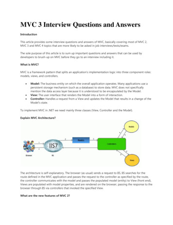
3. Centre lines, section lines are drawn using pencil.a) H b) 2H c) 3H or 4H d) HBAnswer: cExplanation: Centre lines, section lines are drawn using 3H or 4H pencil. Outlines, dottedlines, section-plane lines, dimension lines and arrow heads are drawn using 2H. Thesedifferent pencils give different shades which give different importance to lines in drawing.4. The line given below is used fora) Long-break linec) Centroidal linesb) Cutting planesd) Out lines of adjacent partsAnswer: aExplanation: Lines used to represent cutting planes is chain thin (narrow) with thick (wide)at the ends and at changing of position, lines used to represent centroidal lines andoutlines of adjacent parts are chain thin double-dashed or long-dashed double-dotted(narrow).5. The line given below is used fora) Hidden outlinesc) Hidden edgesb) Cutting planesd) Dimension linesAnswer: bExplanation: Hidden outlines, hidden edges are drawn using dashed thin (narrow) lines.Dimension lines are drawn using continuous thin (narrow) lines (straight or curved). Thegiven type of line in question is used to represent cutting planes.6. Dashed thick (wide) line is represented byAnswer: cExplanation: The other lines are continuous thin (narrow) (straight or curved) whichareused for grid, dimension. Dashed thin (narrow) is used for hidden outlines. A Chain thinlong-dashed dotted (narrow) line is used for centre line, lines of symmetry etc.11
7. Match the following.a) 1, i; 2, ii; 3, iii; 4, ivb) 1, ii; 2, iii; 3, i; 4, ivc) 1, ii; 2, iv; 3, iii; 4, id) 1, iv; 2, iii; 3, ii; 4, iAnswer: bExplanation: Thick-thin-thick are used for cutting planes, dashed thick (wide) is used forsurface treatment, zigzag lines are used for long-break lines and continuous thin line isused for dimensions, extensions and projection lines.8. Match the following.a) 1, i; 2, ii; 3, iii; 4, ivb) 1, ii; 2, iii; 3, iv; 4, ic) 1, ii; 2, iv; 3, iii; 4, id) 1, iv; 2, iii; 3, ii; 4, iAnswer: bExplanation: Thick-thin-thick are used for cutting planes, dashed thick (wide) is used forsurface treatment, chain thick or long dashed dotted (wide) is used for indication of lines orsurfaces to which a special requirement applies and continuous thin line is used fordimensions, extensions and projection lines.9. Drawing pencils are graded according to increase in relativea) diameterb) sharpnessc) lengthd) hardnessAnswer: dExplanation: Drawing pencils are graded according to increase in relative hardness. They12
are marketed with the labeled as H, 2H, 3H, 4H, 5H, 6H etc. These grades are used forgetting accurate, clean and neat drawings.10. Match the following.1. Dimension linesi.Continuous thick lines2. Extension or Projection lines ii.Continuous thin lines3. Margin linesiii.Continuous thick lines4. Outlinesiv.Continuous thin linesa) 1, i; 2, ii; 3, iii; 4, ivb) 1, ii; 2, iii; 3, iv; 4, ic) 1, ii; 2, iv; 3, iii; 4, id) 1, iv; 2, iii; 3, ii; 4, iAnswer: cExplanation: Dimension lines are continuous thin lines, are terminated at the outer ends bypointed arrowheads. Extension lines continuous thin lines extend by about 3mm beyondthe dimension lines. Margin lines are continuous thick or wide lines along which the printsare trimmed. Outlines are continuous thick or wide lines.11. Short-break lines are drawn freehand while long-break lines are ruled lines.a) Trueb) FalseAnswer: aExplanation: Short-break lines are continuous, thin and wavy. They are drawn withfreehand and are used to show a short-break, or irregular boundaries. Long-break lines arethin ruled lines with short zigzags within them.13
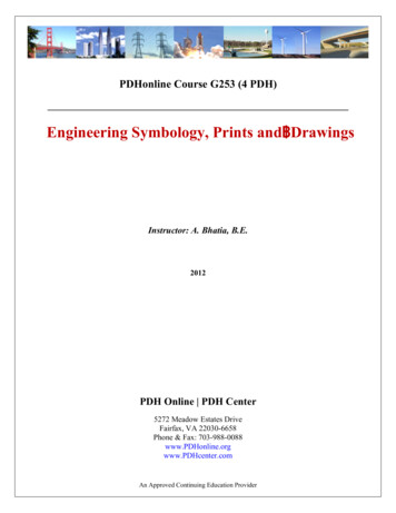
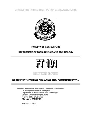
Different Types of Lines – 21. In engineering drawing, which type of line indicates that there is a change ofplane?a) Continuous thin wavyb) Long chain thinc) Continuous thickd) Medium thick short dashesAnswer: cExplanation: In engineering drawing, a change of plane is indicated by drawing continuousthick lines. Continuous thin lines are used for indicating dimension line, hatching line,revolved section, etc. Long chain lines are used to indicate center line, cutting lines.2. Which of the following lines are used to show that the object is cut and thenviewed?a) Hidden linesb) Leader linesc) Centre linesd) Hatching LinesAnswer: dExplanation: Hatching lines are used to show that the orthographic view is drawn after asection of the object is cut. They indicate that the object is cut and it shows the remainingsolid body. Hidden lines are used to indicate holes or slots.3. What do hidden lines in orthographic projections denote?a) Holes or slotsb) Change of Planec) Position of cutd) Centre of a circle or cylinderAnswer: aExplanation: Hidden lines denote those parts which cannot be seen when viewing theobject. They are used when there are holes or slots in the object, if they cannot be vieweddirectly. Change of plane is indicated by outlines. Position of cut is denoted by section line.14
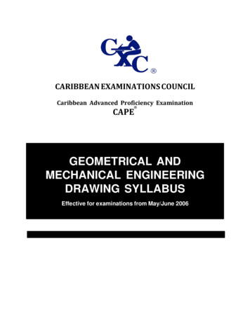
4. From the fbelow figure, what is the name of the line X?a) Outlineb) Section linec) Hidden lined) HatchingAnswer: cExplanation: Hidden lines are dashed lines with dashes equaling 2mm and the gap 1mm.These lines depict that there is a hole or slot i.e. no solid part is present there. Section lineare long chain thin lines with thick ends.5. What is the type of line used for line a?a) Continuous thickb) Continuous thin straightc) Medium thick short dashesd) Continuous thin wavyAnswer: bExplanation: Continuous thin straight lines are used to denote the dimensions of the object.Thin lines are used so as to distinguish between outline and the dimension line.Continuous thin wavy lines are used to indicate short breaks or irregular boundary line.6. The axis of the cylinder or sphere is denoted by which of the following line?a) Section lineb) Centre linec) Hidden lined) Leader lineAnswer: b15
Explanation: Centre line shows the axis of the cylinder or sphere. These lines generallypass through the centre of the circle. For a cylinder, they generally are parallel to the heightof the cylinder. For circles, two centre lines are drawn perpendicular to each other passingthrough the centre of the circle.7. What is the standard length and width of the arrowhead of dimension lines?a) 2mm and 2mmb) 3mm and 1mmc) 4mm and 2mmd) 3mm and 2mmAnswer: bExplanation: Arrowheads of dimension lines have a length of 3mm and 1mm wide. Whendrawing the arrowheads the ratio, length: width is to be maintained at 3:1. The arrowheadscan be drawn with length 6mm and breadth 2mm, since the ratio is the same.8. What is the length of the short dashes of the centre lines?a) 5mmb) 2mmc) 1mmd) 3mmAnswer: bExplanation: Centre line consists of long dash of 8-10mm, a gap of 1mm, short dash of2mm and then a gap of 1mm. This pattern continues throughout the centre line. In case ofsection line, the ends of the section line are thickened. This is how section line and centreline are different.9. Among the following, which of the representation is wrong?a)b)c)d)Answer: bExplanation: For proper dimensioning, it is important for the lines to meet. One line cannotbe in air with respect to the other intersecting line; they should meet at some point. If thelines do not meet, dimensions will not have accuracy.16
10. Which type of line is used to join the dimension line and the curve that needsto be dimensioned?a) Leader lineb) Outlinec) Dimension lined) Section lineAnswer: aExplanation: Leader lines lead the dimension line to the curve that needs to bedimensioned. It is a bridge connecting two lines. Outlines are the main or most prominentlines of the object when viewed for drawing. Dimension lines are used to denote theparticular dimensions.11. What is the difference between the section line and the centre line?a) The length of the long dashesb) The length of short dashesc) The width of the gapd) The two ends of the linesAnswer: dExplanation: The ends of a section line are thickened so as to distinguish it from the centreline. The rest of the section line has the same thickness and dimensions as that of thecentre line. The thickening of the ends in the section line is also used to denote thedirection of viewing.System of Dimensioning – 11. Which are the two systems of placing dimensions? (Options given below)i. Aligned system, ii. Break system, iii. Unidirectional system, iv. Directionalsystema) i, iib) i, iiic) ii, ivd) i, ivAnswer: bExplanation: The two systems of placing dimensions are aligned system and unidirectionalsystem. In the aligned system the dimension is placed perpendicular to the dimension line.17
In unidirectional system all dimensions are placed such that they can be read from thebottom of the drawing sheet.2. Aligned system is used for drawing of air crafts, automobiles.a) Trueb) FalseAnswer: bExplanation: Since the drawing of aircrafts, automobiles etc. are very large it isinconvenient to read dimensions from the right-hand side. So we use unidirectional systemof dimensioning but not aligned system of dimensioning.3. In unidirectional system the dimensions area) Placed above the dimension linesb) Placed below the dimension linesc) Placed by breaking the dimension line in the middled) Placed left side of the dimension lineAnswer: cExplanation: In unidirectional system all dimensions are placed such that they can be readfrom the bottom of the drawing sheet. The dimension lines are broken near the middle forinserting the dimensions. This is used in mainly large drawings.4. In aligned system the dimensions area) Placed parallel to the dimension lineb) Placed perpendicular to the dimension linec) Placed left side of the dimension lined) Placed right side of the dimension lineAnswer: bExplanation: In the aligned system the dimension is placed perpendicular to the dimensionline. The dimensions should be placed near the middle and above, but clear of thedimension lines.5. From unidirectional system, it isa) Convenient to read dimensions from the bottom edgeb) Convenient to read dimensions from the right-hand edgec) Convenient to read dimensions from the right-hand edged) Convenient to read dimensions from the top edgeAnswer: aExplanation: Unidirectional system of dimensioning is used for large drawings. So the18
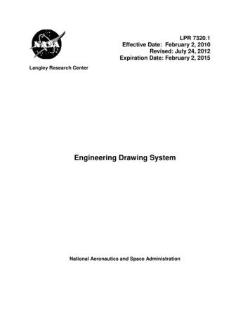
dimensions are placed by breaking the dimension line near the middle. Also all dimensionsare so placed that they can be read from the bottom edge.6. Match the followinga) 1, i; 2, ii; 3, iii; 4, ivb) 1, ii; 2, iii; 3, i; 4, ivc) 1, iv; 2, iii; 3, i; 4, iid) 1, iv; 2, i; 3, ii; 4, iiiAnswer: cExplanation: An arrowhead is placed at each end of a dimension line. The pointed endtouches the outline or an extension line. The length of the arrowhead should be aboutthree times its maximum width.7. Match the followinga) 1, i; 2, ii; 3, iii; 4, ivb) 1, ii; 2, iii; 3, i; 4, ivc) 1, iv; 2, iii; 3, i; 4, iid) 1, iv; 2, i; 3, ii; 4, iiiAnswer: cExplanation: An arrowhead is placed at each end of a dimension line. The size of anarrowhead should be proportional to the thickness of the outlines. It is drawn freehand withtwo strokes made in the direction of its pointed end. The space between them is neatlyfilled up.19
8. In which system of dimensioning the figures can read from bottom as well asright hand side of the drawing?a) Aligned systemb) Unidirectional systemc) Nonaligned multidirectional systemd) Parallel systemAnswer: aExplanation: In aligned system of dimensioning, the dimension figures are written in such away that they can read from the bottom and right hand side of the drawing. It increases theeffort in reading the dimensions.System of Dimensioning – 21. Which of the following dimension is according to the ‘aligned system’ ofdimensioning?a) 40b) 55c) 25d) 10Answer: aExplanation: In aligned system of dimensioning, the dimensions are written on thedimension line. Their alignment is along the length of the dimension line. The dimensionsare always written either on top or below the dimension line but never cutting it.2. In dimensioning, the lines enclosing the dimension line are known asa) Leader lineb) Dimension line20
c) Extension lined) OutlineAnswer: cExplanation: The extension line encloses the dimension line. It starts and ends with
Explanation: 45o can be drawn using 45o Set-square, and 30o, 60o can be drawn using 30o – 60o Set-square, but to draw 75o degrees we need both Set-squares. That is only if we keep 30o of set-square adjacent with 45o set-square we can get 75o. And also multiple ang


![Engineering Graphics Essentials [4th Edition]](/img/13/978-1-58503-610-3-1.jpg)