Transcription
Kirstie PlantenbergEngineering Graphics Essentialswith AutoCAD 2018 Instruction Text and Video InstructionSDCP U B L I C AT I O N SBetter Textbooks. Lower Prices.www.SDCpublications.comACCESS CODEUNIQUE CODE INSIDE
Visit the following websites to learn more about this book:Powered by TCPDF (www.tcpdf.org)
[ Chapter 2: Drawing in AutoCAD ]CHAPTER 2DRAWING IN AUTOCAD CHAPTER OUTLINE2.1) INTRODUCTION . 52.1.1) Navigating through the AutoCAD tutorials . 52.2) AUTOCAD’S WORKSPACES AND USER INTERFACE. 72.3) THE DRAWING AREA . 72.4) ACCESSING AUTOCAD COMMANDS . 92.4.1) Application button . 92.4.2) The ribbon . 102.4.3) Tool palettes . 122.4.4) Command prompt / window . 132.4.5) Shortcut menus . 142.4.6) Application status bar . 142.4.7) Quick access toolbar . 152.4.8) Touch screen . 152.5) STARTING, SAVING, AND OPENING DRAWINGS . 162.5.1) Starting a new drawing . 162.5.2) Saving and opening a drawing . 182.5.3) File tab . 182.5.4) Autodesk 360 . 192.6) CUSTOMIZE USER INTERFACE (CUI) . 202.7) USER INTERFACE AND STARTUP TUTORIAL . 202.7.1) Setting up the user interface . 202.7.2) Starting a new drawing . 242.7.3) Saving your drawing as a template . 262.7.4) Checking your drawing parameters . 272.8) COORDINATES . 272.8.1) Cartesian and polar coordinates . 272.8.2) Cartesian coordinate system. 272.8.3) Polar Coordinates . 282.8.4) Relative coordinates . 302.8.5) World coordinate system (WCS) and user coordinate system (UCS) . 312.8.6) The coordinates panel . 332.8.7) Coordinate position . 342.9) WCS/UCS COORDINATE SYSTEMS TUTORIAL . 342.9.1) Coordinates. 342.9.2) Change to the user coordinate system (UCS). 362.9.3) Coordinate display and drawing . 372.9.4) Drawing using the UCS coordinate system . 372.10) DRAWING USING COORDINATES TUTORIAL . 382.10.1) Drawing a rectangle using Cartesian coordinates . 392-1
[ Chapter 2: Drawing in AutoCAD ]2.10.2) Drawing using relative polar coordinates. 412.10.3) Drawing using both Cartesian and polar coordinates . 422.11) PRINTING . 432.11.1) Page setup . 442.11.2) Plot . 452.11.3) Printing to scale . 452.12) PRINTING TUTORIAL. 462.12.1) Creating the drawing . 462.12.2) Printing . 472.12.3) Printing to scale . 492.12.4) Printing to PDF . 512.13) DRAW COMMANDS . 512.13.1) Line . 522.13.2) Construction line . 522.13.3) Ray . 532.13.4) Polyline. 532.13.5) Polygon . 542.13.6) Rectangle . 542.13.7) Arc . 552.13.8) Circle . 552.13.9) Spline . 562.13.10) Ellipse. 572.13.11) Point . 572.14) TEXT . 582.14.1) Style . 582.14.2) Single-line text . 582.14.3) Multi-lined text . 592.15) MODIFY COMMANDS . 602.15.1) Selecting objects . 612.15.2) Erase . 612.15.3) Copy . 612.15.4) Mirror . 622.15.5) Offset. 632.15.6) Array. 642.15.7) Move . 662.15.8) Rotate. 672.15.9) Scale . 682.15.10) Stretch . 692.15.11) Lengthen . 692.15.12) Trim . 702.15.13) Extend . 702.15.14) Break . 712.15.15) Join. 722.15.16) Chamfer . 732.15.17) Fillet. 732.15.18) Blend curves . 742.15.19) Explode . 742.16) OBJECT SNAP COMMANDS . 742-2
[ Chapter 2: Drawing in AutoCAD ]2.16.1) Endpoint . 772.16.2) Midpoint . 772.16.3) Intersection . 772.16.4) Apparent intersection . 772.16.5) Extension . 772.16.6) Center . 782.16.7) Quadrant . 782.16.8 ) Tangent . 792.16.9) Perpendicular . 792.16.10) Parallel . 792.16.11) Nearest . 802.16.12) Snap from . 802.16.13) Insert . 802.16.14) Node . 812.16.15) Geometric Center . 812.16.16) Object snaps settings . 812.16.17) Object snap cycling and aperture. 822.17) WAGON TUTORIAL. 832.17.1) Preparing to draw. 832.17.2) Drawing . 842.17.3) Using modify commands . 882.18) SELECTING OBJECTS . 892.19) OBJECT SELECTION TUTORIAL . 902.19.1) Selecting objects using the pickbox. . 902.19.2) Selecting objects using a window . 922.20) OBJECT SNAP TUTORIAL . 942.20.1) Drawing using osnaps . 942.20.2) Trimming . 1012.21) POLAR TRACKING . 1022.22) OBJECT SNAP TRACKING . 1032.23) TRACKING TUTORIAL . 1042.23.1) Polar tracking . 1042.24) DYNAMIC INPUT . 1082.25) DYNAMIC INPUT TUTORIAL . 1092.25.1) Dynamic input settings . 1092.26) GRIP BOXES. 1112.27) GRIP BOX TUTORIAL . 1122.27.1) Preparing to draw. 1122.27.2) Fixing the drawing . 1132.27.3) Modifying the drawings shape. 1162.28) PARAMETRIC DRAWING . 1182.28.1) Geometric constraints . 1182.28.2) Dimensional constraints . 1192.29) APPLYING PARAMETRIC CONSTRAINTS TUTORIAL . 1202.29.1) Applying geometric constraints . 1202.29.2) Applying dimensional constraints . 1232.30) AUTOMATIC PARAMETRIC CONSTRAINTS TUTORIAL . 1262-3
[ Chapter 2: Drawing in AutoCAD ]DRAWING IN AUTOCAD QUESTIONS. 129DRAWING IN AUTOCAD PROBLEMS . 1412-4
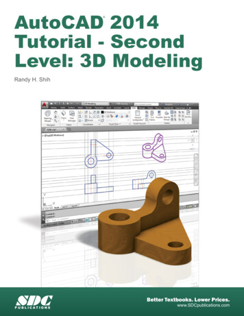
[ Chapter 2: Drawing in AutoCAD ]CHAPTER SUMMARYIn this chapter you will learn how to navigate through and create drawings withinAutoCAD’s 2-D drawing workspace. Entities within the AutoCAD environment are created withina coordinate framework. Objects such as Lines, Circles, Polygons, etc are created using a setof defining coordinates points. Although this may sound complex, AutoCAD makes creatingprofessional looking engineering drawings very simple. By the end of this chapter you will be ableto create and edit complex geometries.2.1) INTRODUCTIONAutoCAD allows you to visualize, document and share a design idea in either a2-D or 3-D environment. This chapter will focus on AutoCAD’s 2-D drawing capabilities.AutoCAD gives you the tools to create accurate and professional looking detailed andassembly drawings. Figure 2.1-1 shows a detailed drawing created in AutoCAD’s 2-Ddrawing workspace.Figure 2.1-1: AutoCAD drawing example2.1.1) Navigating through the AutoCAD tutorialsThe AutoCAD tutorials presented in this book have specific objectives which arestated at the beginning. Each tutorial is designed to introduce the user to a particularfeature of AutoCAD or to a set of commands. As you will see, there are several ways toaccess AutoCAD’s commands. For each command sequence, the tutorial will usuallystate one or two ways to access a command. This doesn’t mean that you would not beable to access it in another way.The format of each tutorial is consistent. For each step, a general statement ofwhat is to be accomplished is given, followed by a command sequence that takes you stepby step through the process. Within the tutorials the font, capitalization, and boldness of2-5
[ Chapter 2: Drawing in AutoCAD ]the text are used to convey information. The text format scheme used in each tutorial isas follows: Underlined text: Gives a location of where the command or options should beentered or selected. Italic text: Gives the name of a window, palette, ribbon, tab, or a field. Bold text: Text that should be typed in the Command window or into a field toaccess a command. Many AutoCAD commands may be entered in an abbreviatedform. The “line” command may be accessed by typing the full word LINE or by justtyping L. Therefore, when a command is written in full within a tutorial containedin this book, only the capitalized letters need to be typed. For example, if you seeELlipse, you may type the full word but you only need to type EL. Bold italic text: Represents the name of a command, toggle, button, or icon thatshould be selected. Bold Courier font: Indicates a key on the keyboard that needs to be pressed. Normal text: Gives instructions. Courier font: Represents AutoCAD prompts within the Command window.An example of a command sequence from one of the tutorials is given in thefollowing example. The command sequence illustrates the use of text format to conveyinformation. The command sequence is used to create a line that is arrayed around anexisting circle.Example of an AutoCAD tutorial command sequence1) Create a total of 16 sun rays using a polar ARray. Each sun rayLine is 0.5 inches long.a) Command: l or line orDraw toolbar:b) Specify first point: QUADrant orObject Snap toolbar:of Select the right side quadrant of the sunbody circle.c) Specify next point or [Undo]: @.5 0d) Specify next point or [Undo]: Entere) Command: ARray or Modify toolbar:i.ii.iii.iv.v.vi.Select objects: Select the line.Select objects: EnterEnter array type [Rectanglular/PAth/POlar] Rectangular : POSpecify center point of array or [Base point/Axis of rotation]: cenor Select the center of the circle.Select grip to edit array or [ASsociative/Base point/Items/Anglebetween /Fill angle/ROWs/Levels/ROTate items/eXit] eXit : Fvii. Specify the angle to fill ( ccw, - cw) or [EXpression] 360 : 360viii. Select grip to edit array or [ASsociative/Base point/Items/Anglebetween /Fill angle/ROWs/Levels/ROTate items/eXit] eXit : Iix. Enter number of items in array or [Expression] 6 : 16x. Select grip to edit array or [ASsociative/Base point/Items/Anglebetween /Fill angle/ROWs/Levels/ROTate items/eXit] eXit : Enter2-6
[ Chapter 2: Drawing in AutoCAD ]2.2) AUTOCAD’S WORKSPACES AND USER INTERFACEAutoCAD has three predefined workspaces: Drafting & Annotation, 3D Basicsand 3D Modeling. Each workspace allows for easy access to operations that are relevantto the current workspace.AutoCAD’s user interface is workspace dependent. We will focus on the Drafting& Annotation workspace in this book. The Drafting & Annotation workspace userinterfaces are shown in Figure 2.2-1. The important areas of the interfaces are identifiedand will be discussed in the sections indicated.2.4) Application button2.4) Ribbon2.4) Quick access toolbar2.3) Drawing window2.5) File tab2.5) Design feed palette2.9) Drawing cursorNavigation bar2.9) Coordinate axisModel & Layout space2.4) Command prompt / window2.4) Status barFigure 2.2-1: Drafting & Annotation workspace user interface2.3) THE DRAWING AREAThe drawing area/window is the place where you create and view your drawing.The background color of the drawing window may be changed to suit the user’s preferenceas shown in Figure 2.3-1.The drawing area is as large as you need it to be. The usable drawing area doesnot just consist of the area that you can see. You can pan around the drawing area using2-7
[ Chapter 2: Drawing in AutoCAD ]the Pan command to reveal areas of your drawing that are out of view. You can alsoZoom in and out to reveal more or less of the drawing area. Both the Pan and Zoomcommands are located in the Utilities ribbon panel in the Home tab or the Standard toolbar.You can also pan and zoom by manipulating the mouse wheel. Pan: Hold down the mouse wheel and move the mouse. Zoom: Rotate the mouse wheel. Zoom All: Double click the mouse wheel.Figure 2.3-1: Drawing area background colorChanging the drawing area’s background color1) Application button: Select the Optionsicon at the bottom of the menu.2) Options window – Display tab: Select the Colors button.3) Drawing Window Colors window:a) Context field: Select 2D model spaceb) Interface element field: Select Uniform backgroundc) Color field: Select your color preference.d) Select the Apply & Close button.Because the drawing area is so large, it is a good idea to indicate the region thatyou wish to use. This is your drawing size or limits. This is usually the area that will beprinted. You can change your drawing size using the LIMITS command.2-8
[ Chapter 2: Drawing in AutoCAD ]Setting your drawing size1) Command: limits2) Specify lower left corner or [ON/OFF] 0.0000,0.0000 : Enter (The lower leftcorner of your limits should always remain 0,0.)3) Specify upper right corner 420.0000,297.0000 : 280,216 (This changes a Metricdrawing area to the equivalent of an 11 x 8.5 sheet of paper.)The units (i.e., inches, millimeters, feet) used to draw objects in the drawing areacan be selected using the UNits command.Setting your drawing units, precision and angle directions1) Command: UNits2) Drawing Units window: Use this window to set your units and precision.2.4) ACCESSING AUTOCAD COMMANDSAutoCAD allows its users to access commands in many different ways, one ofwhich will no doubt become your favorite. The most common ways of accessingAutoCAD’s commands within the Drafting & Annotation workspace are through theapplication button, ribbon, command window, shortcut menus, and status bar.2.4.1) Application buttonMenus are available through the Application button in the upper left corner of thedrawing window. These menus contain the commands used to create, save, print andmanage your drawing. Figure 2.4-1 shows the Application button. The Search menu(near the top) allows you to perform a keyword command search. The search even worksfor commands that are not directly accessible through the Application button. Note the2-9
[ Chapter 2: Drawing in AutoCAD ]location of the Options button at the bottom. This button will be referenced several timesin the upcoming tutorials.ApplicationbuttonOptionsFigure 2.4-1: Application button2.4.2) The ribbonThe Ribbon provides, in a single location, commands that are relevant to thecurrent workspace. It is organized into a series of tabs. Several ribbon panels are locatedin each tab area. Each panel contains related commands. Figure 2.4-2 shows the Drafting& Annotation workspace Ribbon. Individual ribbon panels may be expanded by clickingon the black arrow located in the bottom right corner of each panel. Once the mousemoves off of an expanded panel, the panel will collapse unless it is pinned. The ribbonmay be docked horizontally or vertically. When it is docked vertically, the text tabs arereplaced with icons. The ribbon as a whole or individual panels may float freely anywherein the drawing window. Panels may also be added to or removed from a specific ribbontab. This requires accessing the CUI (Customize User Interface) manager.Ribbon tabsRibbon panelMinimize to panel titlesExpands the panelpinnedFigure 2.4-2: The Ribbon2 - 10not pinned
[ Chapter 2: Drawing in AutoCAD ]Floating and docking ribbon panels1) Floating: Click on a ribbon panel title and drag it to the drawing window.2) Docking: Once the panel is floating, it may be moved, sent back to the ribbon, or theorientation may be changed.MoveSend to RibbonToggle orientationTooltips appear when your mouse hovers over an icon. For the first few secondsan abbreviated tooltip appears. If the mouse remains over the icon, an expanded tooltipwill appear as shown in Figure 2.4-3. The tooltips help you navigate through the commandsteps if you are uncertain how to proceed. Tooltip appearance may be modified byaccessing in the Display tab of the Options window (Application button – Options D
The drawing area/window is the place where you create and view your drawing. The background color of the drawing window may be changed to suit the user’s preference as shown in Figure 2.3-1. The drawing area is as large as you need it to be. The usable drawing


![Engineering Graphics Essentials [4th Edition]](/img/13/978-1-58503-610-3-1.jpg)