![Engineering Graphics Essentials [4th Edition]](/img/13/978-1-58503-610-3-1.jpg)
Transcription
ENGINEERING GRAPHICSESSENTIALSFourth EditionText and Independent Learning DVDKirstie PlantenbergUniversity of Detroit MercySDCPUBLICATIONSwww.SDCpublications.comSchroff Development Corporation
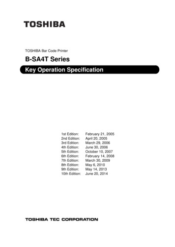
Chapter 1: Orthographic ProjectionORTHOGRAPHIC PROJECTIONIn Chapter 1 you will learn the importance of engineering graphics and howto create an orthographic projection. An orthographic projection describes theshape of an object. It is a two dimensional representation of a three dimensionalobject. Different line types are used to indicate visible, hidden and symmetrylines. By the end of this chapter, you will be able to create a technically correctorthographic projection using proper projection techniques.1.1) INTRODUCTION TO ENGINEERING GRAPHICSEngineering graphics is a set of rules and guidelines that help you create anengineering drawing. An engineering drawing is a drawing or a set of drawings thatcommunicates an idea, design, schematic, or model. Engineering drawings come inmany forms. Each engineering field has its own type of engineering drawings. Forexample, electrical engineers draw circuit schematics and circuit board layouts. Civilengineers draw plans for bridges and road layouts. Mechanical engineers draw partsand assemblies that need to be manufactured. This book focuses on the latter. This isnot to say that only students in a mechanical engineering curriculum will benefit fromlearning engineering graphics. It benefits everyone from the weekend carpenter whowants to draw plans for his/her new bookshelf to the electrical engineer who wants toanalyze electrical component cooling using a CAE program. Engineering graphicsteaches you how to visualize and see all sides of an object in your mind. Being able tovisualize in your mind will help you in several aspects of critical thinking.1.2) ORTHOGRAPHIC PROJECTION INTRODUCTIONAn orthographic projection enables us to represent a 3-D object in 2-D (see Figure1-1). An orthographic projection is a system of drawings that represent different sides ofan object. These drawings are formed by projecting the edges of the objectperpendicular to the desired planes of projection. Orthographic projections allow us torepresent the shape of an object using 2 or more views. These views together withdimensions and notes are sufficient to manufacture the part.1-1
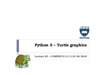
Chapter 1: Orthographic ProjectionFigure 1-1: Orthographic projection.1.2.1) The Six Principle ViewsThe 6 principle views of an orthographic projection are shown in Figure 1-2. Eachprinciple view is created by looking at the object in the directions indicated in Figure 1-2and drawing what is seen as well as what is hidden from view.Figure 1-2: The six principle views.1-2
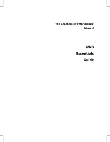
Chapter 1: Orthographic Projection1.3) THE GLASS BOX METHODTo obtain an orthographic projection, an object is placed in an imaginary glass boxas shown in Figure 1-3. The sides of the glass box represent the six principle planes.Images of the object are projected onto the sides of the box to create the six principleviews. The box is then unfolded to lie flat, showing all views in a 2-D plane. Figure 1-4shows the glass box being unfolded to create the orthographic projection of the object.Figure 1-3: Object in a glass box.1-3
Chapter 1: Orthographic ProjectionFigure 1-4: Glass box being unfolded.1-4
Chapter 1: Orthographic ProjectionInstructor Led Exercise 1-1: Principle viewsLabel the five remaining principle views with the appropriate view name.What are the differences between the Right Side and Left Side views?What are the differences between the Top and Bottom, and Front and Rear views?Which view(s) have the least number of hidden or dashed lines?1-5
Chapter 1: Orthographic Projection1.4) THE STANDARD VIEWSWhen constructing an orthographic projection, we need to include enough views tocompletely describe the true shape of the part. The more complex a part, the moreviews are needed to describe it completely. Most objects require three views tocompletely describe them. The standard views used in an orthographic projectionare the front, top, and right side views. The other views (bottom, rear, left side) areomitted since they usually do not add any new information. It is not always necessary touse the three standard views. Some objects can be completely described in one or twoviews. For example, a sphere only requires one view, and a block only requires twoviews.1.4.1) The Front ViewThe front view shows the most features or characteristics of the object. Itusually contains the least number of hidden lines. The exception to this rule is when theobject has a predefined or generally accepted front view. All other views are based onthe orientation chosen for the front view. The top, front, and bottom views are all alignedvertically and share the same width dimension. The left side, front, right side, and rearviews are all aligned horizontally and share the same height dimension (see the figureshown in Exercise 1-1).1.5) LINE TYPES USED IN AN ORTHOGRAPHIC PROJECTIONLine type and line weight provide valuable information to the print reader. Forexample, the type and weight of a line can answer the following questions: Is the featurevisible or hidden from view? Is the line part of the object or part of a dimension? Is theline indicating symmetry?There are four commonly used line types: continuous, hidden, center and phantom.The standard recommends using, no less than, two line widths. Important lines shouldbe twice as thick as the less important thin lines. Common thicknesses are 0.6 mm forimportant lines and 0.3 mm for the less important lines. However, to further distinguishline importance, it is recommended to use four different thicknesses or weights: thin,medium, thick, and very thick. The actual line thickness should be chosen such thatthere is a visible difference between the line weights; however, they should not be toothick or thin making it difficult to read the print. The thickness of the lines should beadjusted according to the size and complexity of the part. The following is a list ofcommon line types and widths used in an orthographic projection.1. Visible lines: Visible lines represent visible edges and boundaries. The line type iscontinuous and the line weight is thick (0.5 - 0.6 mm).2. Hidden lines: Hidden lines represent edges and boundaries that cannot be seen.The line type is dashed and the line weight is medium thick (0.35 - 0.45 mm).3. Center lines: Center lines represent axes of symmetry and are important forinterpreting cylindrical shapes. Crossed center lines should be drawn at the centersof circles. They are also used to indicate circle of centers and paths of motion. Theline type is long dash – short dash and the line weight is thin (0.3 mm).1-6
Chapter 1: Orthographic Projection4. Phantom lines: Phantom lines are used to indicate imaginary features. Forexample, they are used to indicate the alternate positions of moving parts, andadjacent positions of related parts. The line type is long dash – short dash – shortdash and the line weight is usually thin (0.3 mm).5. Dimension and Extension lines: Dimension and extension lines are used to show thesize of an object. In general, a dimension line is placed between two extension linesand is terminated by arrowheads, which indicates the direction and extent of thedimension. The line type is continuous and the line weight is thin (0.3 mm).6. Cutting plane lines: Cutting plane lines are used to show where an imaginary cuthas been made through the object in order to view interior features. The line type isphantom and the line weight is very thick (0.6 to 0.8 mm). Arrows are placed atboth ends of the cutting plane line to indicate the direction of sight.7. Section lines: Section lines are used to show areas that have been cut by the cuttingplane. Section lines are grouped in parallel line patterns and usually drawn at a 45 angle. The line type is usually continuous and the line weight is thin (0.3 mm).8. Break lines: Break lines are used to show imaginary breaks in objects. A break lineis usually made up of a series of connecting arcs. The line type is continuous andthe line weight is usually thick (0.5 – 0.6 mm).Instructor Led Exercise 1-2: Line typesUsing the line type definitions, match each line type name with the appropriate linetype. Visible Line Hidden Line Center Line Phantom Line Dimension and Extension Lines Cutting Plane Line Section Lines Break Line1-7
Chapter 1: Orthographic ProjectionInstructor Led Exercise 1-3: Line use in an orthographic projectionFill the following dotted orthographic projection with the appropriate line types.1.6) RULES FOR LINE CREATION AND USEThe rules and guide lines for line creation should be followed in order to create linesthat are effective in communicating the drawing information. However, due to computerautomation, some of the rules may be hard to follow.1.6.1) Hidden LinesHidden lines represent edges and boundaries that cannot be seen.Rule 1. The length of the hidden line dashes may vary slightly as the size of thedrawing changes. For example, a very small part may require smaller dashesin order for the hidden line to be recognized.1-8
Chapter 1: Orthographic ProjectionRule 2. Hidden lines should always begin and end with a dash, except when the hiddenline begins or ends at a parallel visible line (see Figure 1-5).Figure 1-5: Drawing hidden lines.Rule 3. Dashes should join at corners (see Figure 1-6).Figure 1-6: Hidden lines at corner.1.6.2) Center LinesCenter lines represent axes of symmetry and are important for interpreting cylindricalshapes (Figure 1-7). They are also used to indicate circle of centers and paths of motionas shown in Figure 1-8.Figure 1-7: Axes of symmetry1-9
Chapter 1: Orthographic ProjectionFigure 1-8: Center line usesRule 1. Center lines should start and end with long dashes (see Figure 1-8).Rule 2. Center lines should intersect by crossing either the long dashes or the shortdashes (see Figure 1-9).Figure 1-9: Crossing center lines.1 - 10
Chapter 1: Orthographic ProjectionRule 3. Center lines should extend a short distance beyond the object or feature. Theyshould not terminate at other lines of the drawing (see Figure 1-10).Figure 1-10: Terminating center lines.Rule 4. Center lines may be connected within a single view to show that two or morefeatures lie in the same plane as shown in Figure 1-11. However, they shouldnot extend through the space between views.Figure 1-11: Connecting center lines.1.6.3) Phantom LinesPhantom lines are used to indicate alternate positions of moving parts (see Figure 18). They may also be used to indicate adjacent positions of related parts and repeateddetail as shown in Figures 1-12 and 1-13. They are also used to show fillets and roundsin the view that does not show the radius. In this case, the phantom lines are used toshow a change in surface direction (see Figure 1-14).1 - 11
Chapter 1: Orthographic ProjectionRule 1. Phantom lines should start and end with a long dash.Figure 1-12: Related part.Figure 1-13: Repeated detail.Figure 1-14: Phantom lines used to indicated a change in surface direction1 - 12
Chapter 1: Orthographic Projection1.6.4) Break LinesBreak lines are used to show imaginary breaks in an object. For example, whendrawing a long rod, it may be broken and drawn at a shorter length as shown in Figure1-15.Figure 1-15: Using break lines.There are two types of break lines. A break line may be a series of connecting arcs,as shown in Figure 1-15, or a straight line with a jog in the middle as shown in Figure 116. If the distance to traverse is short the series of connecting arcs is used. This seriesof arcs is the same width as the visible lines on the drawing. If the distance is long thethin straight line with a jog is used.Figure 1-16: Types of break lines.1.6.5) Line Type PrecedenceSome lines are considered more important than other lines. If two lines occur inthe same place, the line that is considered to be the least important is omitted.Lines in order of precedence/importance are as follows:1.2.3.4.Cutting plane lineVisible lineHidden lineCenter line1 - 13
Chapter 1: Orthographic Projection1.7) CREATING AN ORTHOGRAPHIC PROJECTIONThe steps presented in this section are meant to help you create a technically correctorthographic projection using the 3rd angle projection standard. To understand andvisually see how views are created using the 3rd angle projection standard, put your righthand on a table palm up. You are looking at the front view of your hand. Now rotateyour hand so that your thumb points up and your little finger is touching the table. This isthe right side view of your hand. Put your hand back in the front view position. Nowrotate your hand so that your finger tips are pointing up and your wrist is touching thetable. This is the top view of your hand.The following steps will take you through the creation of an orthographic projection.Once you become experienced and proficient at creating orthographic projections, youwill develop short cuts and may not need to follow the steps exactly as written. Thesesteps are visually illustrated in Figure 1-17.1.2.Choose a front view. This is the view that shows the most about the object.Decide how many views are needed to completely describe the object. If youare unable to determine which views will be needed, draw the standard views(front, top and right side).Draw the visible features of the front view.Draw projectors off of the front view horizontally and vertically in order to createthe boundaries for the top and right side views.Draw the top view. Use the vertical projectors to fill in the visible and hiddenfeatures.Project from the top view back to the front view. Use the vertical projectors tofill in any missing visible or hidden features in the front view.Draw a 45 projector off of the upper right corner of the box that encloses the frontview.From the top view, draw projectors over to the 45 line and down in order tocreate the boundaries of the right side view.Draw the right side view.Project back to the top and front view from the right side view as needed.Draw center lines where necessary.3.4.5.6.7.8.9.10.11.Following the aforementioned steps will insure that the orthographic projection isdone correctly. That is, it will insure that: The front and top views are vertically aligned.The front and right side views are horizontally aligned.Every point or feature in one view is aligned on a projector in any adjacent view(front and top, or front and right side).The distance between any two points of the same feature in the related views(top and right side) are equal.Figure 1-17 identifies the adjacent and related views. Adjacent views are twoadjoining views aligned by projectors. Related views are views that are adjacent to thesame view.1 - 14
Chapter 1: Orthographic ProjectionFigure 1-17: Creating an orthographic projection1.7.1) Projection SymbolIn the United States, we use 3rd angle projection to create an orthographic projection.This is the method of creating orthographic projections that is described in this chapter.In some parts of Europe and elsewhere 1st angle projection is used. To inform the printreader what projection method was used, the projection symbol should be placed in thebottom right hand corner of the drawing. If the drawing uses metric units, the text “SI” isplaced in front of the projection symbol. The projection symbols are shown in Figure 118. Figure 1-19 shows the projection symbol’s proportions.1 - 15
Chapter 1: Orthographic ProjectionFigure 1-18: First and third angle projection symbols.Figure 1-19: Projection symbol proportions.1 - 16
Chapter 1: Orthographic ProjectionIn Class Student Exercise 1-4: Missing lines 1Name: Date:Fill in the missing lines in the front, right side, and top views. Hint: The front viewhas one missing visible line. The right side view has one missing visible line andtwo missing hidden lines. The top view has five missing visible lines and twomissing hidden lines.1 - 17
Chapter 1: Orthographic ProjectionNOTES:1 - 18
Chapter 1: Orthographic ProjectionIn Class Student Exercise 1-5: Missing lines 2Name: Date:Fill in the missing lines in the top, front, and right side views. Hint: The top viewhas one missing visible line. The front view has four missing visible lines and fourmissing center lines. The right side view has two missing hidden lines and onemissing center line.1 - 19
Chapter 1: Orthographic ProjectionNOTES:1 - 20
Chapter 1: Orthographic ProjectionVideo Exercise 1-6: Beginning Orthographic ProjectionThis video exercise will take you through creating an orthographic projection for theobject shown.1 - 21
Chapter 1: Orthographic ProjectionVideo Exercise 1-7: Intermediate Orthographic ProjectionThis video exercise will take you through creating an orthographic projection for theobject shown.1 - 22
Chapter 1: Orthographic ProjectionIn Class Student Exercise 1-8: Drawing an orthographic projection 1Name: Date:Shade in the surfaces that will appear in the front, top, and right side views.Estimating the distances, draw the front, top, and right side views. Identify thesurfaces with the appropriate letter in the orthographic projection.1 - 23
Chapter 1: Orthographic ProjectionNOTES:1 - 24
Chapter 1: Orthographic ProjectionIn Class Student Exercise 1-9: Drawing an orthographic projection 2Name: Date:Identify the best choice for the front view. Estimating the distances, draw the front,top, and right side views.1 - 25
Chapter 1: Orthographic ProjectionNOTES:1 - 26
Chapter 1: Orthographic ProjectionVideo Exercise 1-10: Advanced Orthographic ProjectionThis video exercise will take you through creating an orthographic projection for theobject shown. Note: The object is not completely dimensioned; however, the missingdimensions will be made apparent in the video.1 - 27
Chapter 1: Orthographic Projection1.8) AUXILIARY VIEWSAuxiliary views are used to show the true shape of features that are not parallel toany of the principle planes of projection. Auxiliary views are aligned with the angledfeatures from which they are projected. Partial auxiliary views are often used to shownonly a particular feature that is not described by true projection in the principle views.Figure 1-20 shows the use of auxiliary views.Figure 1-20: Auxiliary views.1 - 28
Chapter 1: Orthographic ProjectionVideo Exercise 1-11: Auxiliary ViewsThis video exercise takes you through creating the auxiliary views for the followingobject.1 - 29
Chapter 1: Orthographic ProjectionNOTES:1 - 30
Chapter 1: Orthographic ProjectionIn Class Student Exercise 1-12: Auxiliary viewName: Date:Draw the auxiliary view for this object.1 - 31
Chapter 1: Orthographic ProjectionNOTES:1 - 32
Chapter 1: Orthographic ProjectionORTHOGRAPHIC PROJECTION CROSSWORD PUZZLEName: The thickest line type on a non-sectioned orthographic projection.The standard views used in an orthographic projection in alphabetical order.The front and right side views are aligned .Projection or construction lines are not shown on the final drawing. (true, false)An orthographic projection is a . representation of an object?Phantom line use: Used to indicate .1 - 33
Chapter 1: Orthographic ProjectionDown1.3.4.5.7.Phantom line use: Used to indicate .Center line use: Used in indicate axes of .The top and front views are aligned .The view that generally contains the least number of hidden lines.If a hidden line and center line appear in exactly the same location on a drawing,which one do you delete?8. To indicate line importance we draw line using different line .9. Should a center line end at the boundary of an object?11. In the United States . angle projection is used.1 - 34
Chapter 1: Orthographic ProjectionORTHOGRAPHIC PROJECTION PROBLEMSName: Date:P1-1) Sketch the front, top and right side views of the following object. Use the gridprovided.1 - 35
Chapter 1: Orthographic ProjectionNOTES:1 - 36
Chapter 1: Orthographic ProjectionName: Date:P1-2) Sketch the front, top and right side views of the following object. Use the gridprovided.1 - 37
Chapter 1: Orthographic ProjectionNOTES:1 - 38
Chapter 1: Orthographic ProjectionName: Date:P1-3) Sketch the front, top and right side views of the following object. Use the gridprovided.1 - 39
Chapter 1: Orthographic ProjectionNOTES:1 - 40
Chapter 1: Orthographic ProjectionName: Date:P1-4) Sketch the front, top and right side views of the following object. Use the 5x5 mmgrid provided.1 - 41
Chapter 1: Orthographic ProjectionNOTES:1 - 42
Chapter 1: Orthographic ProjectionName: Date:P1-5) Sketch the front, top and right side views of the following object. Use the gridprovided.1 - 43
Chapter 1: Orthographic ProjectionNOTES:1 - 44
Chapter 1: Orthographic ProjectionName: Date:P1-6) Sketch the front, top and right side views of the following object. Use the gridprovided.1 - 45
Chapter 1: Orthographic ProjectionNOTES:1 - 46
Chapter 1: Orthographic ProjectionName: Date:P1-7) Sketch the front, top and right side views of the following object. Use the gridprovided.1 - 47
Chapter 1: Orthographic ProjectionNOTES:1 - 48
Chapter 1: Orthographic ProjectionName: Date:P1-8) Sketch the front, top and right side views of the following object. Use the gridprovided.1 - 49
Chapter 1: Orthographic ProjectionNOTES:1 - 50
Chapter 1: Orthographic ProjectionName: Date:P1-9) Sketch the front, top and right side views of the following object. Use the gridprovided.1 - 51
Chapter 1: Orthographic ProjectionNOTES:1 - 52
Chapter 1: Orthographic ProjectionName: Date:P1-10) Sketch the front, top and right side views of the following object. Use the gridprovided.1 - 53
Chapter 1: Orthographic ProjectionNOTES:1 - 54
Chapter 1: Orthographic ProjectionName: Date:P1-11) Sketch the front, top and right side views of the following object. Use the gridprovided.1 - 55
Chapter 1: Orthographic ProjectionNOTES:1 - 56
Chapter 1: Orthographic ProjectionName: Date:P1-12) Sketch the front, top and right side views of the following object. Use the gridprovided.1 - 57
Chapter 1: Orthographic ProjectionNOTES:1 - 58
Chapter 1: Orthographic ProjectionName: Date:P1-13) Sketch the front, top and right side views of the following object. Use the gridprovided.1 - 59
Chapter 1: Orthographic ProjectionNOTES:1 - 60
Chapter 1: Orthographic ProjectionName: Date:P1-14) Sketch the front, top and right side views of the following object. Use the gridprovided.1 - 61
Chapter 1: Orthographic ProjectionNOTES:1 - 62
Chapter 1: Orthographic ProjectionName: Date:P1-15) Sketch the front, top and right side views of the following object. Use the gridprovided.1 - 63
Chapter 1: Orthographic ProjectionNOTES:1 - 64
Chapter 1: Orthographic ProjectionName: Date:P1-16) Sketch the front, top and right side views of the following object. Use the gridprovided.1 - 65
Chapter 1: Orthographic ProjectionNOTES:1 - 66
Chapter 1: Orthographic ProjectionName: Date:P1-17) Sketch the front, top and right side views of the following object. Use the gridprovided.1 - 67
Chapter 1: Orthographic ProjectionNOTES:1 - 68
Chapter 1: Orthographic ProjectionName: Date:P1-18) Sketch the front, top and right side views of the following object. Use the gridprovided.1 - 69
Chapter 1: Orthographic ProjectionNOTES:1 - 70
Chapter 1: Orthographic ProjectionName: Date:P1-19) Given two complete views, sketch in the missing view.1 - 71
Chapter 1: Orthographic ProjectionNOTES:1 - 72
Chapter 1: Orthographic ProjectionName: Date:P1-20) Given two complete views, sketch in the missing view.1 - 73
Chapter 1: Orthographic ProjectionNOTES:1 - 74
Chapter 1: Orthographic ProjectionName: Date:P1-21) Given two complete views, sketch in the missing view.1 - 75
Chapter 1: Orthographic ProjectionNOTES:1 - 76
Chapter 1: Orthographic ProjectionName: Date:P1-22) Given two complete views, sketch in the missing view.1 - 77
Chapter 1: Orthographic ProjectionNOTES:1 - 78
Chapter 1: Orthographic ProjectionName: Date:P1-23) Given two complete views, sketch in the missing view.1 - 79
Chapter 1: Orthographic ProjectionNOTES:1 - 80
Chapter 1: Orthographic ProjectionName: Date:P1-24) Given two complete views, sketch in the missing view.1 - 81
Chapter 1: Orthographic ProjectionNOTES:1 - 82
Chapter 1: Orthographic ProjectionName: Date:P1-25) Given two complete views, sketch in the missing view.1 - 83
Chapter 1: Orthographic ProjectionNOTES:1 - 84
Chapter 1: Orthographic ProjectionName: Date:P1-26) Given two complete views, sketch in the missing view.1 - 85
Chapter 1: Orthographic ProjectionNOTES:1 - 86
Chapter 1: Orthographic ProjectionName: Date:P1-27) Sketch in a complete auxiliary view in the space indicated.1 - 87
Chapter 1: Orthographic ProjectionNOTES:1 - 88
Chapter 1: Orthographic ProjectionName: Date:P1-28) Sketch in a complete auxiliary view in the space indicated.1 - 89
Chapter 1: Orthographic ProjectionNOTES:1 - 90
Chapter 1: Orthographic ProjectionName: Date:P1-29) Finish the two incomplete auxiliary views.1 - 91
Chapter 1: Orthographic ProjectionNOTES:1 - 92
Chapter 1: Orthographic ProjectionP1-30) Use a CAD package to create an orthographic projection of the following object.Draw the three standard views. Print using appropriate pen widths and insert a titleblock.P1-31) Use a CAD package to create an orthographic projection of the following object.Draw the three standard views. Print using appropriate pen widths and insert a titleblock.1 - 93
Chapter 1: Orthographic ProjectionP1-32) Use a CAD package to create an orthographic projection of the following object.Draw the three standard views. Print using appropriate pen widths and insert a titleblock.1 - 94
Chapter 1: Orthographic ProjectionP1-33) Use a CAD package to create an orthographic projection of the following object.Draw the three standard views. Print using appropriate pen widths and insert a titleblock.P1-34) Use a CAD package to create an orthographic projection of the following object.Draw the three standard views. Print using appropriate pen widths and insert a titleblock.1 - 95
Chapter 1: Orthographic ProjectionP1-35) Use a CAD package to create an orthographic projection of the following object.Draw the three standard views. Print using appropriate pen widths and insert a titleblock.1 - 96
Chapter 1: Orthographic ProjectionP1-36) Use a CAD package to create an orthographic projection of the following object.Draw the three standard views. Print using appropriate pen widths and insert a titleblock.P1-37) Use a CAD package to create an orthographic projection of the following object.Draw the three standard views. Print using appropriate pen widths and insert a titleblock.1 - 97
Chapter 1: Orthographic ProjectionP1-38) Use a CAD package to create an orthographic projection of the following object.Draw the three standard views. Print using appropriate pen widths and insert a titleblock.P1-39) Use a CAD package to create an orthographic projection of the following object.Draw the three standard views. Print using appropriate pen widths and insert a titleblock.1 - 98
Chapter 1: Orthographic ProjectionP1-40) Use a CAD package to create an orthographic projection of the following object.Draw the three standard views. Print using appropriate pen widths and insert a titleblock.1 - 99
Chapter 1: Orthographic ProjectionP1-41) Use a CAD package to create an orthographic projection of the following object.Draw the three standard views. Print using appropriate pen widths and insert a titleblock.1 - 100
Chapter 1: Orthographic ProjectionP1-42) Use a CAD package to create an orthographic projection of the following object.Draw the three standard views. Print using appropriate pen widths and insert a titleblock.1 - 101
Chapter 1: Orthographic ProjectionP1-43) Use a CAD package to create an orthographic projection of the following object.Draw the three standard views. Print using appropriate pen widths and insert a titleblock.1 - 102
Chapter 1: Orthographic ProjectionP1-44) Use a CAD package to create an orthographic projection of the following object.Draw the three standard views. Print using appropriate pen widths and insert a titleblock.1 - 103
Chapter 1: Orthographic ProjectionP1-45) Use a CAD package to create an orthographic projection of the following object.Draw the three standard vie
1.1) INTRODUCTION TO ENGINEERING GRAPHICS Engineering graphics is a set of rules and guidelines that help you create an engineering drawing. An engineering drawing is a drawing or a set of drawings that communicates an idea, design, schematic, or model.