Transcription
CE 100Civil Engineering Drawing Sessional(Lab Manual)Department of Civil EngineeringAhsanullah University of Science and TechnologyNovember, 20171
PrefaceThis course is designed to provide civil engineering undergraduates with basic understandingof the theory and practice of engineering drawings. Students will learn to read and constructall architectural, structural and other drawings by means of discussions and drawingexamples related to existing buildings or projects. It includes lettering, plane geometry,different geometric constructions, types of lines, perspective projections, orthographicprojections, structural floor plan of a building and detailing for typical reinforced concretestructural members.This Lab manual was prepared with the help of “Beginner’s guide to Engineering Drawing”by Dr. E. R. Latifee and some other lecture notes.Md. Asif HossainDepartment of Civil EngineeringAhsanullah University of Science and TechnologyUpdated byMd. Ajwad AnwarSudipta Dey TirthaSyed Aaqib JavedDepartment of Civil EngineeringAhsanullah University of Science and Technology2
Table of ContentsTraditional Drawing Tools . 4Standard Engineering Lettering . 7Different Geometric Constructions . 15Types of Lines . 22Perspective Projections. 33Orthographic Projections and Isometric Drawing . 42Structural drawing – Plan view, Elevation view and Cross sectional view . 55Structural drawing –Isolated footing and beam longitudinal and cross sectional views . 61Structural drawing – Slab and Stair reinforcement detailing . 64Appendix 1 . 67Appendix 2 . 723
Topic 1Traditional Drawing Tools4
DrawingA drawing is a graphic representation of an object, or a part of it, and is the result ofcreative thought by an engineer or technician. When one person sketches a rough mapin giving direction to another, this is graphic communication. Graphic communicationinvolves using visual materials to relate ideas. Drawings, photographs, slides,transparencies, and sketches are all forms of graphic communication. Any medium thatuses a graphic image to aid in conveying a message, instructions, or an idea is involvedin graphic communication.Engineering drawing:The engineering drawing, on the other hand, is not subtle, or abstract. It does notrequire an understanding of its creator, only an understanding of engineering drawings.An engineering drawing is a means of clearly and concisely communicating all of theinformation necessary to transform an idea or a concept in to reality. Therefore, anengineering drawing often contains more than just a graphic representation of itssubject. It also contains dimensions, notes and specifications.5
6
Topic 2Standard Engineering Lettering7
Elements of Engineering DrawingEngineering drawing are made up of graphics language and word language.Graphics language: Describe a shape (mainly).Word language: Describe an exact size, location and specification of the object.8
Lettering in Engineering DrawingLettering is used to provide easy to read and understand information to supplement a drawingin the form of notes and annotations. Lettering is an essential element in both traditionaldrawing and Computer Aided Design (CAD) drawing. Thus, it must be written with:Legibility – shape & space between letters and words.Uniformity – size & line thickness.Types of LetteringThe two types of lettering are:1. Double Stroke Lettering: In Double Stroke Lettering the line width is greater than that ofSingle Stroke Lettering.Double Stroke Lettering is further divided into:a) Double Stroke Vertical Gothic Lettering.b) Double Stroke Inclined Gothic Lettering.A stencil is mostly used when hand drawing double stroked letters.2. Single Stroke Lettering: Thickness in single stroke lettering is obtained by a single strokeof pencil or ink pen. It is further divided into:(a) Single Stroke Vertical Gothic Lettering.(b) Single Stroke Inclined Gothic Lettering.Conventions for Lettering Use all CAPITAL LETTERS.Use even pressure to draw precise, clean lines.Use one stroke per line.Horizontal Strokes are drawn left to right.Vertical Strokes are drawn downward.Curved strokes are drawn top to bottom in one continuous stroke on each side.Use The Single-stroke, Gothic Style of Lettering.Always Skip A Space Between Rows Of Letters.Always Use Very Light Guide Lines.Fractions Are Lettered Twice the Height Of Normal Letters.Fraction Bars Are Always Drawn Horizontal.Use a Medium Lead For Normal Lettering.Use a Hard Lead For Drawing Guide Lines.9
Placement of Text on Engineering Drawings10
Basics of Single StrokingSpacingUniformity in spacing of letters is a matter of equalizing spaces by eye. The background area between letters, not the distance between them, should beapproximately equal. Words are spaced well apart, but letters within words should be spaced closely. For either upper case or lower-case lettering, make the spaces between wordsapproximately equal to a capital O.11
Space between lettersDrawing scalesScale is the ratio of the linear dimension of an element of an object shown in the drawing tothe real linear dimension of the same element of the object.12
Designation of a scale consists of the word “SCALE” followed by the indication of its ratio,as follows:Dimension numbers shown in the drawing correspond to “true size” of the object and they areindependent of the scale used in creating that drawing.13
Try with one-fourth (0.25) inches distance between the lines, in both the directions (Xand Y axes)14
Topic 3Different Geometric Constructions15
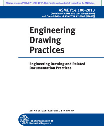
Objectives:At the end of this chapter students should be able to: Define geometric nomenclatures like angles, lines etc Discuss the steps to construct different geometric figures like lines, arcs, polygon, ellipseetc.Introduction :Strict interpretation of geometric construction allows use of only the compass and aninstrument for drawing straight lines, and with these, the geometer, following mathematicaltheory, accomplishes his solutions. In technical drawing, the principles of geometry areemployed constantly, but instruments are not limited to the basic two as T-squares, triangles,scales, curves etc. are used to make constructions with speed and accuracy. Since there iscontinual application of geometric principles, the methods given in this chapter should bemastered thoroughly.GEOMETRIC NOMENICLATUREA. POINTS IN SPACEA point is an exact location in space or on a drawing surface. A point is actuallyrepresented on the drawing by a crisscross at its exact location. The exact point in space iswhere the two lines of the crisscross intersect. When a point is located on an existing line,a light, short dashed line or cross bar is placed on the line at the location of the exactpoint. Never represent a Point on a drawing by a dot; except for sketching locations.B. LINELines are straight elements that have no width, but are infinite in length (magnitude), andthey can be located by two points which are not on the same spot but fall along the line.Lines may be straight lines or curved lines. A straight line is the shortest distance betweentwo points. It can be drawn in any direction. If a line is indefinite, and the ends are notfixed in length, the actual length is a matter of convenience. If the end points of a line areimportant, they must be marked by means of small, mechanically drawn crossbars, asdescribed by a pint in space. Straight lines and curved lines are considered parallel if theshortest distance between them remains constant. The symbol used for parallel line is //.Lines, which are tangent and at 90 degree are considered perpendicular. The symbol forperpendicular line is .C. ANGLESAn angle is formed by the intersection of two lines. There are three major kinds of angles:right angels, acute angles and obtuse angles. The right angle is an angle of 900, an acuteangle is an angle less than 900, and an obtuse angle is an angle more than 900. A straightline is 1800. The symbol for an angle is (singular) and ’s (Plural). To draw an angle,use the drafting machine, a triangle, or a protractor.16
D. TRIANGLESA triangle is a closed plane figure with three straight sides and their interior angles sumup exactly 1800. The various kinds of triangles: a right triangle, an equilateral triangle, anisosceles triangle, and an obtuse angled triangle.E. QUADRIALTERALIt is a plane figure bounded by four straight sides. When opposite sides are parallel, thequadrilateral is also considered to be a parallelogram.F. POLYGONA polygon is a closed plane figure with three or more straight sides. The most importantof these polygons as they relate to drafting are probably the triangle with three sides,square with four sides, the hexagon with six sides, and the octagon with eight sides.17
F1. Regular PentagonF2. Regular Hexagon18
F3. Regular OctagonG1. Ellipse (Parallelogram Method)19
G2. Ellipse Concentric Circles MethodH. Hyperbola20
I. PARABOLA21
Topic 4Types of Lines22
Introduction to Types of Lines23
Visible/Object Lines Dark, heavy lines.Used to represent the outline or contour of the object being drawn.Define features you can see in a particular view.Hidden Lines Light, narrow, short, dashed lines.Shows the outline of a feature that cannot be seen in a particular view.Used to help clarify a feature, but can be omitted if they clutter a drawing.Hidden lines should always begin and end with a dash. Exception: When the hiddenline begins or ends at a parallel visible or hidden line.Dashes should join at corners.24
Section Lines Thin line usually drawn at a 45 degree angle.Indicates the material that has been cut through in a sectional view.Center Lines Thin line consisting of alternating long and short dashes.Used to represent the center of round or cylindrical features, or the symmetry of a feature.Center lines should start and end with long dashes.25
Center lines should intersect by crossing either the long dashes or the short dashes.Center lines should extend a short distance beyond the object or feature. Center lines may be connected within a single view to show that two or more features liein the same plane. Center lines should not extend through the space between views.Dimension Lines Thin lines capped on the ends with arrowheads and broken along their length to provide aspace for the dimension numeral.They indicate length.26
Extension LinesThin lines used to establish the extent of a dimension. Can also be used to show extension ofa surface to a theoretical intersection as shown in (b). Begin 1.5mm from the object andextend to 3mm beyond the last dimension. They should not cross dimension lines.Leader Lines Thin lines used to connect a specific note to a feature.Also used to direct dimensions, symbols, item number and part numbers on a drawing.Commonly drawn at 45, 30 and 60 degrees.Has a short shoulder (3-6mm) at one end beginning at the center of the vertical height oftext, and a standard dimension arrowhead at the other end touching the feature.Leader lines should not cross each other.Leader lines should not be excessively long.Leader lines should not be vertical or horizontal.Leader lines should not be parallel to dimension lines, extension lines or section lines.Arrowheads Used to terminate dimension lines and leader lines and on cutting-plane lines and viewingplane lines.They should be three times as long as they are wide.They should be the same size throughout the drawing.The filled arrowhead is generally preferred because of its clarity.27
Cutting Plane Lines Thick broken line that is terminated with short 90 degree arrowheads.Shows where a part is mentally cut in half to better see the interior detail.Break LinesBreak Lines are used to break out sections for clarity or for shortening a part.Three types of break lines with different line weights:a) Short Break Lines. Thick wavy line. Used to break the edge or surface of a part for clarity of a hidden surface.28
b) Long Break Lines Long, thin lines. Used to show that the middle section of an object has been removed so it can be drawn ona smaller piece of paper.c) Cylindrical Break Lines. Thin lines. Used to show round parts that are broken in half to better clarify the print or to reduce thelength of the object.29
Phantom Lines Thin lines made up of long dashes alternating with pairs of short dashes.Three purposes in drawings: To show the alternate position of moving parts. To show the relationship of parts that fit together. To show repeated detail.Line PrecedenceIf two lines occur in the same place, the line that is considered to be the least important isomitted. Lines in order of precedence/importance are as follows:- Cutting plane line- Visible line- Hidden line- Centerline30
Example31
32
Topic 5Perspective Projections33
Projection Projections transform points from n (here, n 3) dimensional space into a space ofdimension less than n (here, n 2) Points to be considered,- Location of object- Location of observer- Plane of projectionProjectors/lines of projection34
Parallel ProjectionsParallel Projection is a type of projection where the line of sight or projectors are parallel andare perpendicular to the picture planes. It is subdivided in to the following three categories:Orthographic, Oblique and Axonometric Projections. Orthographic projections: are drawn as multi view drawings, which show flatrepresentations of principal views of the subject. Oblique Projections: actually show the full size of one view. Axonometric Projections: are three-dimensional drawings, and are of three differentvarieties:Isometric, Dimetric and Trimetric.Orthographic Projections Orthographic projections are drawings where the projectors, the observer or station pointremain parallel to each other and perpendicular to the plane of projection. Orthographic projections are further subdivided into axonometric projections and multiview projections. Effective in technical representation of objects.35
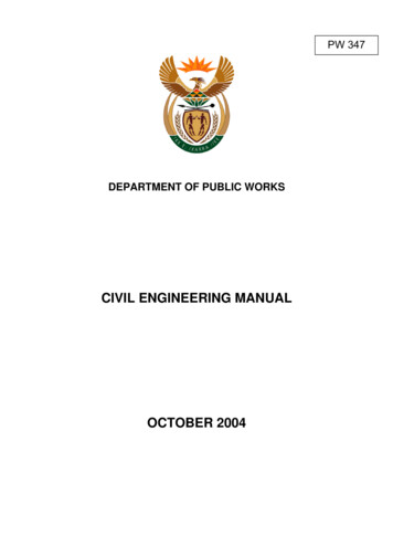
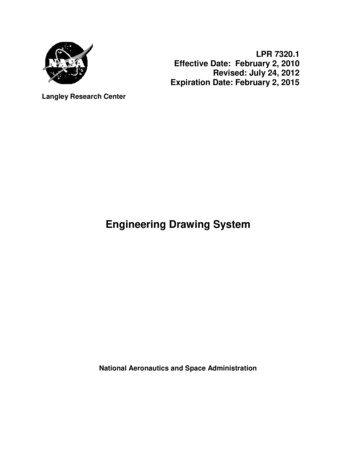
Oblique Projections Projectors are parallel to each other but not perpendicular to projection plane. An oblique projection shows front and top surfaces that include the three dimensions ofheight, width, and depth. The front or principal surface of an object (the surface toward the plane of projection) isparallel to the plane of projection. Effective in pictorially representing objects.Figure: Oblique drawingPerspective Projections36
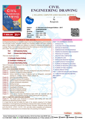
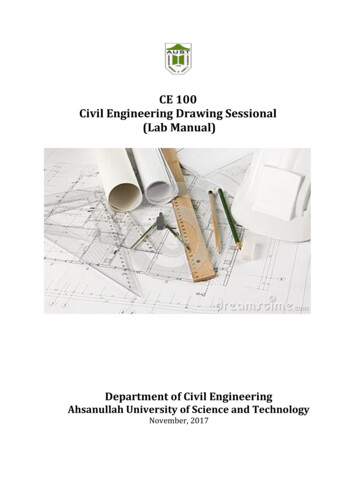
Perspective projections are drawings which attempt to replicate what the human eye actuallysees when it views an object. There are three types of perspective projections: One-point,Two-point and Three-point Projections.Figure: Perspective projectionThree point perspective projection:Some real world examples of one 1 point, 2 point and 3 point Perspective projection:37
Figure: One Point Perspective Projections38
Figure: Two Point Perspective Projections39
40
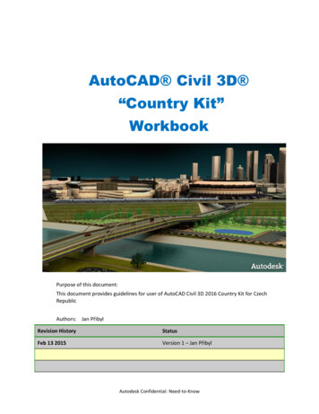
Figure: Three Point Perspective Projections41
Topic 6Orthographic Projections and Isometric Drawing42
IntroductionOrthographic projection 2-D representation of a 3-D object.The Six Principal ViewsThe 6 principal views are created by looking at the object, straight on, in the directionsindicated.The Glass Box Method The object is placed in a glass box.The sides of the box represent the 6 principal planes.The image of the object is projected on the sides of the box.Things to notice: The projection planes. The projectors. How surfaces A and B are projected.The box is unfolded creating the 6 principal views.43
44
Standard ViewsWhen constructing an orthographic projection, we need to include enough views tocompletely describe the true shape of the part. Complex part more views Simple part less viewsFront ViewThe front view shows the most features or characteristics of the object.- It usually contains the least amount of hidden lines.- The front view is chosen first and the other views are based on the orientation of thefront view.View Alignment The top and front views are aligned vertically and share the same width dimension. The front and right side views are aligned horizontally and share the same heightdimension.45
1.46
2.47
3.48
4.49
5.50
Orthographic to Isometric Drawing51
52
53
Assignment54
Topic 7Structural drawing – Plan view, Elevation view and Crosssectional view55
56
57
58
59
60
Topic 8Structural drawing –Isolated footing and beamlongitudinal and cross sectional views61
Cross Section of an Isolated column footing62
63
Topic 9Structural drawing – Slab and Stair reinforcementdetailing64
65
66
Appendix 1Lab Report Format1. All students must have a same colored printed cover page. The design of cover pageis provided with the lab manual. Students have to compose only the course teacher’sname and designation and their information.2. An index is provided. It should be printed and set after the cover page. Table may befilled up by pen during each submission after that particular subject has been covered.3. Each report must have a common top page. Only the experiment name and no. andthe date may be filled up by pen. A top page design is provided.4. A4 papers have to be used for preparing the lab report.67
CE 100Civil Engineering Drawing Sessional(Lab Report)Prepared ForName of Course TeacherDesignation of Course Teacher&Name of Course TeacherDesignation of Course TeacherPrepared ByName of StudentStudent’s IDYear/ SemesterGroup68
INDEXTopicno.Topic NameDate ofSubmission69SignatureCommentsPageno.
INDEXTopicno.Topic NameDate ofSubmission70SignatureCommentsPageno.
CE 100Civil Engineering Drawing Sessional(Lab Report)Experiment No. :Experiment Name:Date of Performance:Date of Submission:Prepared ForName of Course TeacherDesignation of Course Teacher&Name of Course TeacherDesignation of Course TeacherPrepared ByName of StudentStudent’s IDYear/ SemesterGroup71
Appendix 2Lab Instructions1. All students must be present at the class just in time.2. All students must have to submit the lab report just after the entrance and before theclass start.3. Lab reports have to be submitted serially according to Student’s ID.4. Strict discipline must be maintained in the classroom. Useless chattering andgossiping during class time in the teachers’ presence is not acceptable under anycircumstances whatsoever.72
The engineering drawing, on the other hand, is not subtle, or abstract. It does not require an understanding of its creator, only an understanding of engineering drawings. An engineering drawing is a means of clearly and concisely communicating all of the information neces