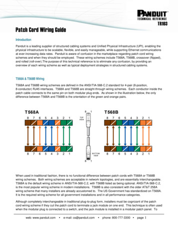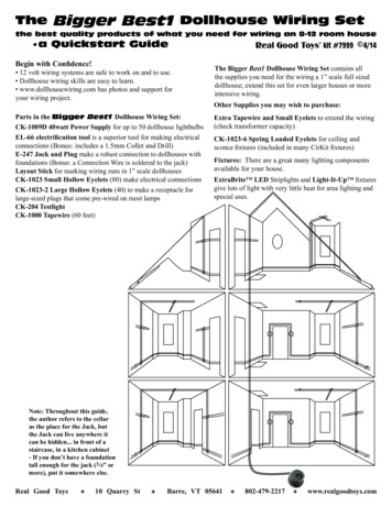
Transcription
Electrical, Parts & Troubleshooting ManualFor Pachislot, Pachisuro or Kaidoshiki YugikiWiring from the Aristocrat / Rodeo / Sammy-NOTICEThis manual is prepared for the use of entertainment only. To the best of my knowledge theinformation gathered here by myself in this document is accurate about the Aristocrat,Rodeo & Sammy Pachislot machines. In no way, shape or form is this document associatedwith the KK Aristocrat Technologies, Inc., Rodeo Corporation and or the SammyCorporation. In no way shape or form does the author, Aristocrat Technologies, Inc., RodeoCorporation and or the Sammy Corporation take any responsibility for the accuracy of thedata in this document or how it may be used. You the reader take full responsibility for anydamages that may occur to any Pachislot machine by means of this documentation. Thisdocument has been put together as an aid for learning about the operation of the Pachislotmachines and is strictly to be used for entertainment purposes --------------------------------------Written by Charlie C. Form #0001 Rev. B 2014
TABLE OF CONTENTSGENERAL INFORMATION . Introduction General Information .Lubricants & Cleaners Internal Component Locations . . .External Component Locations . . . ELECTRICAL WIRING OF MACHINE .Wiring Diagram of Machine Typical Wiring of Cables Ribbon Cable Wiring .ELECTRICAL & MECHANICAL OPERATION .Audio Sound Board . Control Input Board . CPU System Infrastructure Board Fluorescent Starter Board & Light Bulbs . .Frame Lighting Boards .Belly Glass . .Hopper . .L.C.D. Display Board . .Medal (Token) Acceptor . Power Supply . . . .Power Supply Control Board . . . .Power Supply Service Board . Reels . .Reel Light Board & Light Bulbs . . .Reel Light Control Board . . .Reel Motor Control Board . . .Relay Status Board (Intensive External Terminal Board) . . .Skill Stop Board . Special Chance Lighting Board . Start Lever Spin Knob . .MISC. PARTS LIST . PACHILSO ERROR CODES . . .IMPORTANT WEBSITES & INFO . 26-2728-293031323334-363738394041422
GENERAL INFORMATIONDisconnect the electric power tothe machine before any servicing of the unitcan begin.SPECIFICATIONSElectrical110VAC 50/60HZ 10Amps24VAC 6-10Amps Internal VoltagesWeight70-95 lbs.Measurements34”x24”x13” H*W*LTOOLS REQUIREDStandard set of hand toolsVolt MeterField Service Grounding KitCLEANER & POLISHERSRubbing Alcohol - Medals (Tokens)Acceptor & hopperElectrical Spray - sensors & switches, & hopperMild dish detergent - glass, reels and exterior of unit.Novus Plastic Polish - for any plastic exterior of unit.GENERAL INFORMATIONPachislot, Pachisuro, Kaidoshiki Yugiki, orPachislot is the Japanses Skill Slot Machine. Flashmemory is used to preserve credits, last game, etc.AGEThe Pachislot can be in service for no more than2 years in a Pachi Parlor in Japan.MEDALS (TOKENS) ACCEPTEDBYOAC and MAME Medals (Tokens) size is .984 or25mm in size. Medals (Tokens) weigh about 4.4 oz. or124.73 grams on average. A bet consist of 1 to 3Medals (Tokens) and play across 1-7 different lines perspin. Max of 53 Medals (Tokens) credits can be held bythe machine for credit at any one given time. The hoppercan hold about 1,200 Medals (Tokens) max.BOARD INFORMATIONAll Boards with the beginning part # of SS weremanufactured for the Sammy Corporation by the CMKElectronics WUXI.REEL STOP BUTTONSIt is preferable that the operation of the stop button hasa structure for stopping the rotation of the rotatingcylinder corresponding to the stop button and that thereis no irregularities. The player operates the stop buttonand the reel must stop within 0.19 seconds of the stopbutton associated to the real has been pressed. Thereels can't slip no more than 4 symbols.REEL INFORMATION21 symbols patterns per reel, not to exceed 10different symbols per game. Reels are 3 1/8” in.79.375 mm wideSymbols patterns are 3” in. 76.200 mm wide by 1¼” in. 31.7500 mm with a space of 1/8” in. 9.525mm in between Symbols patterns. Reels may notspin faster than 80 revolutions per minute, and muststop within 0.19 seconds of the stop buttonassociated to the real has been pressed. The reelscan't slip no more than 4 symbols.Jackpot Payout’s can range from 60% - 160%200 % if skill is used.6 payout levels, level 6 being the highest payoutlevel.* Level 4 or 5 A.C. & Las Vegas odds 88 - 160%Reel Symbols and CombinationsSymbols * number of reels possible combinations21 symbols per reel \ 2 reels 441 possiblecombinations.21 symbols per reel \ 3 reels 9,261 possiblecomb.21 symbols per reel \ 4 reels 194,481 possiblecomb.21 symbols per reel \ 5 reels 4,084,101 possiblecomb.21 symbols per reel \ 6 reels 85,766,121 possiblecomb.TYPES OF MACHINESTYPE A Big Bonus Machine - Bonus roundmode usually give at least 24 spins and 24guaranteed wins. Big Bonus round is 2 or 3 setswith at least 8 guaranteed in a row wins. The playeris guaranteed a win for each spin. The player needsto hit a certain combination usually the replaysymbols to get into the bonus round. Total winningsis usually 400 – 711 Medals (Tokens) per BigBonus round.Regular Bonus pay out is a 15:1 ratio. This meansfor every 1 medal token played, 15 Medals arereturned to the player. Max return of Medals(Tokens) is 110, and will end when Big BonusEnds.TYPE B Challenge Chance - The same featuresof a Type A machines with a Big Challenge added.You can have the chance to play over 200consecutive games up to 15 minutes with theincreased odds to win above medals tokens. 3 otherfeatures of Pachislot machines are "Stock,"“Renchan”, and “Tenjō”. The game makes the reelsstop instead of slipping off the bonus symbols for afew games. A Big Bonus Game could end and newBig Bonus game start eventually paying out up to10,000 Medals (Tokens) at one time.3
LOCATIONS:Interior Part Locations:4
5
Exterior Part Locations:6
ELECTRICAL & MECHANICAL OPERATION:Wiring Diagram of the Machine:7
Typical Wiring of CablesCable #1Pin # - color wire1 Brown2 Red3 Orange4 Yellow5 Green6 Blue7 Purple8 Grey9 White10 Black11 Brown / White12 Red / WhitePin # - color wire13 Orange / White14 Yellow / White15 Green / White16 Blue / White17 Purple / White18 Grey / White19 White / Black20 Black21 Brown22 Red23 Orange24 YellowCable #2Pin # - color wire1 White / Black2 Black3 Brown4 Red5 Orange6 YellowCable #3 Speaker WiringPin # - color wire1 Red, Blue or Black2 White8
Ribbon Cable Wiring(AWM Standard IDE Cable)Reel Motor Control Board CN2 Header 30 pins &Relay Status Board CN1 Header 30 pinstoReel Motor Control Board CN1 Header 40 pins &CPU System Infrastructure Board CN4 Header 40 pinsReel MotorControlBoard CN2 /RelayStatusBoardCN1 pin #Cable13Reel MotorControlBoard CN1 /CPU SystemInfra. BoardCN4 pin #Cable35, 3633, 34,37,38, 392251761871982092110161115121413, 2313141,2,3,41512161117101891982, 4, 27Description 24VdcGround & Signal wires for all reels home switchesRelay Motor Control BD CN4 pin2, CN6 pin 2, & CN8 pin 2After Bonus Reset Input LineCT Bonus - Relay Status Board 24vdc Coil of Signal Switching Relay #5 Fujitsu #SY24WKBB Bonus - Relay Status Board 24vdc Coil of Signal Switching Relay #4 Fujitsu #SY24WK.RB Bonus - Relay Status Board 24vdc Coil of Signal Switching Relay #3 Fujitsu # SY24WKToken Out - Relay Status Board 24vdc Coil of Sensitive Signal Relay #Omron #G6E-134PToken In - Relay Status Board 24vdc Coil of Sensitive Signal Relay #Omron #G6E-134PCasino Fault Monitoring Lines & Relay Motor Control BDCN3 pin 5 (voltage to Left Reel Motor) 24vdcCasino Fault Monitoring Lines & Relay Motor Control BDCN3 pin 4 (voltage to Left Reel Motor) 24vdcCasino Fault Monitoring Lines & Relay Motor Control BDCN3 pin 3 (voltage to Left Reel Motor) 24vdcCasino Fault Monitoring Lines & Relay Motor Control BDCN3 pin 2 (voltage to Left Reel Motor) 24vdcCasino Fault Monitoring Lines & Relay Motor Control BDCN3 Pin1, CN5 pin 1, CN7 pin1 & Power for LED D2Casino Fault Monitoring Lines & Relay Motor Control BDCN5 pin 5 (voltage to Center Reel Motor) 24vdcCasino Fault Monitoring Lines & Relay Motor Control BDCN5 pin 4 (voltage to Center Reel Motor) 24vdcCasino Fault Monitoring Lines & Relay Motor Control BDCN5 pin 3 (voltage to Center Reel Motor) 24vdcCasino Fault Monitoring Lines & Relay Motor Control BDCN5 pin 2 (voltage to Center Reel Motor) 24vdcCasino Fault Monitoring Lines & Relay Motor Control BD
202122242526282930CN7 pin 5 (voltage to Right Reel Motor) 24vdcCasino Fault Monitoring Lines & Relay Motor Control BD7CN7 pin 4 (voltage to Right Reel Motor) 24vdcCasino Fault Monitoring Lines & Relay Motor Control BD6CN7 pin 3 (voltage to Right Reel Motor) 24vdcCasino Fault Monitoring Lines & Relay Motor Control BD5CN7 pin 2 (voltage to Right Reel Motor) 24vdcLeft Reel #1 Stop Control Out (Left Stop Button pressed)Ground of LED D6 (see Reel Motor Control Board CN1 pin28)Center Reel #2 Stop Control Out (Center Stop Buttonpressed)Ground of LED D7 (see Reel Motor Control Board CN1 pin27)Right Reel #3 Stop Control Out (Right Stop Button pressed)Ground of LED D8 (see Reel Motor Control Board CN1 pin26)31Left Reel #1 Stop Control Input30Center Reel #2 Stop Control Input29Right Reel #3 Stop Control Input23Right Reel #1 Home Position Switch activated LED D524Center Reel #2 Home Position Switch activated LED D425Left Reel #3 Home Position Switch activated LED D3Right Reel #3 Stop Control Out (Right Stop Button pressed)26Power wire of LED D8Center Reel #2 Stop Control Out (Center Stop Button27pressed)Power wire of LED D7Left Reel #1 Stop Control Out (Left Stop Button pressed)28Power wire of LED D6Power wires for all reels home switches32Relay Motor Control BD CN4 pin 1, CN6 pin 1 & CN8 pin 140Ground for D2 (power on LED)* CN4 - CN8 are found on the Reel Motor Control Board.* Ribbon Cables are AWM IDE 300v internal appliance wiring cables.10
Audio Sound BoardPart # SS09BC64Manufactured by: Sammy The sticker on the protective cover on the board says;” B88CC 0048K”Audio Chip is a Yamaha #YM2735-F and the board was made by BellCo.The Audio Board puts out the audio, special lighting effects, and Top and BellyGlass Lighting.CN1 Header 11 pins to L.C.D Board CN1 Header 11 pinsCN2 Header 12 pins to Frame Lighting Board Cable splits into 2 cable headersto Top Frame Lighting Board CN1 Header 6 pins and CN2 Header 6 pinsCN3 Header 24 pins cable splits into 2 cablesSpecial Chance Lighting Board CN1 Header 6 pins& Reel Light Control Board CN1 Header 18 pins.CN4 Header 2 pins to Right Speaker pin 1 ( ) wire - 8ohm, 10w per speakerpin 2 is ground. 1 speaker only per twin set of wiresCN5 Header 3 pins to Fluorescent Starter Board CN1 Header 3 pins* Playing Field Glass LightingCN6 Header 16 pins to C.P.U System Infrastructure Board CN1 Header 16 pinsCN7 Header 3 pins to Fluorescent Starter Board CN1 Header 3 pins* Top Belly Glass LightingCN8 Header 2 pins to Left Speaker pin 1 ( ) wire - 8ohm, 10w per speakerpin 2 ground. 1 speaker only per twin set of wiresIC2 CMOS chipIC4 Roland RDAC RPP-8 is a Roland Digital Audio Compression ChipIC5 32Mbit UV Eprom & OTP Eprom11
CN2 Header 12 pin to Frame Lighting BoardCable splits into 2 cables toTop Center Lighting Board CN1 Header 6 pin & CN2 Header 6 pinCN2 pin #1 brown2 Red3 Orange4 Yellow5 Green6 Blue7 Purple8 Grey9 White10 Black11 Brown / White12 Red / WhiteFrame Lighting BoardCN1 pin # / CN2 pin #CN1 - 1CN1 - 2CN1 - 3CN1 - 4CN1 - 5CN1 - 6CN2 - 1CN2 - 2CN2 - 3CN2 - 4CN2 - 5CN2 - 6Straight Thru CableCN3 Header 24 pin - Cable splits into 2 cablesSpecial Chance Lighting Board - CN1 Header 6 pin& Reel Light Board - CN1 Header 18 pinCN3 pin 19-2419 White / Black20 Black21 Brown22 Red23 Orange24 YellowCN3 pin 1-181 - 18Special Chance Lighting BoardCN1 Header 6 pins1 - Ground2 - LP13 - LP24 - LP35 - LP46 - LP5Reel Lighting BoardtoCN1 Header 18 pins1 - 18Straight Thru Cableto-12
Control Input BoardPart # SS07DC02Manufactured by: SammyCN1 Header 3 pins to Door Reset Switch - soft system reset.CN2 Header 2 pins to Medals (Tokens) Acceptor Dump Solenoid discharges everything that is not a parlor Medals (Tokens).CN3 Header 6 pins to Medals (Tokens) Sensors #1 and #2.CN4 Header 11 pins to Skill Stop Board CN1 Header Reel Stop Switches.CN5 Header 6 pins to Start Lever, & Max Bet Switch.CN6 Header 50 pins to C.P.U. Main Board System Infrastructure Board CN3 HeaderCN7 Header 6 pins to Credit / Cash Out, 1 Bet, and 2 Bet Switches.CN8 Header 2 pins to Lower Belly Fluorescent Starter Board CN1 HeaderD1,D2 - Credits Readout - Total of Medals (Tokens) Played.D3,D4,D5 - Game Count - Total Credits Payed Out To Player.D6,D7 - Credits Won - Total Credits Just won.D8 - Programmed Pay Back Percentage Level #1-6.D9,D10 - Start LED - Indicate Bets Made Ready to Spin Reels.D11 - 3 Medals (Tokens) Bet.D12 - 2 Medals (Tokens) Bet.D13 - 1 Medals (Tokens) Bet.D14,D16,D18,D20 - Special Function or Entertainment Lighting.D22 - Medals In - Machine is ready for Medals (Tokens) to be inserted.D23 - Replay Light – A free replay is ready.D24 - Power LEDOn Power On /Off.D25 - Start LeverOff activated / On not activated.D26 - Max BetOn activated / Off not activated.D27 - 2 Medals (Tokens) SwitchOn activated / Off not activated.D28 - 1 Medals (Tokens) SwitchOn activated / Off not activated.D29 - Credit / Cash Out SwitchOn activated cash out credits / Off credits held.D30 - Left Reel Stop Switch on Skill Stop BoardOn not activated / Off activated.D31 - Center Reel Stop Switch on Skill Stop Board On not activated / Off activated.D32 - Right Reel Stop Switch on Skill Stop Board On not activated / Off activated.D33 - Door Reset Switch soft system resetOn not activated / Off activated.D37 - Medals (Tokens) Sensor #1On sensor blocked / Off sensor unblocked.D38 - Medals (Tokens) Sensor #2On sensor blocked / Off sensor unblocked.SW1 - Programming Button - Used to set pay back percentages level #1-6.13
CN1 Header 3 pin Door Reset SwitchSharp Electronics Components # P1A23LC or 1A23LC is aOPIC photo interrupter type switch replaced by part # GP1A23LCVcc power supply 5vdc, D33 is on when not activatedGroundVo voltage out / signal wirePin #123CN2 Header 2 pin Medals (Tokens) Acceptor Dump SolenoidPin #12Marsh Bellofram #T3221Vcc power supply 30vdcGroundCN3 Header 6 pin - Medals (Tokens) Acceptor Medals (Tokens) SensorsPin #123456Sharp Electronic Components # GP2A25Vcc power supply 5vdc, Medals (Tokens) sensor #1 D37 off when not activated.Vo voltage out / signal wire, Medals (Tokens) sensor #1 D37 is on when blockedGround Medals (Tokens) sensor #1Vcc power supply 5vdc, Medals (Tokens) sensor #2 D38 off when not activated.Vo voltage out / signal wire, Medals (Tokens) sensor #2 D38 is on when blockedGround Medals (Tokens) sensor #2CN5 Header 6 pins - Start Lever Switch, & Max Bet SwitchPin #1 Brown2 Red3 Orange4 yellow5 Green6 BlueShinkoh Elecronics Co. LTD # KI1232 Photo Interrupter SwitchVcc power supply 5vdc, Start Lever Switch D25 is on when not activated.Vo voltage out signal wire, Start Lever SwitchGround Start Lever SwitchVcc power supply in 5vdc, Max Bet Switch, D26 is off when not activated.Vo voltage out signal wire, Max Bet SwitchGround Max Bet SwitchCN7 Header 6 pins – Credit / Cash Out, 1 Bet, 2 Bet SwitchesPin #1 Brown2 Red3 Orange4 yellow5 Green6 BlueCredit / Cash Out, 1 Bet, and 2 Bet Switches - Fujisoku Corp. #LTM1-3super-minature pushbutton metal contact SPST switchVcc - power supply in 5vdc, Credit / Cash Out SwitchD29 on means cash out credits as tokens, off means credits are withheld.Ground Credit / Cash Out SwitchVcc power supply in 5vdc, 1 Bet Switch, D28 is off when not activated.Ground 1 Bet SwitchVcc power supply in 5vdc, 2 Bet SwitchD27 is off when not activated.Ground 2 Bet Switch14
CPU System Infrastructure BoardPart # SS098BC02Manufactured by: Sammy CPU is a Star Novax - LE 2080A-PA #T6W058N-0003 - Japan 0211 EAI* Z80 Microprocessor Core Based Instruction Set. LETECH is the Chinesemanufacturing branch of Star Electronics of Japan. The Le 2080A-PA contains 2764 ofone time programmable EPROM. Not erasable or reprogrammable. Electricallyprogrammed through its data and address lines upon initialization. Sanyo also madethis chip at one time.CN1 Header 16 pins to Audio Sound Board CN6 Header 16 pinsCN2 Header 20 pins to Power Supply Control Board CN3 Header 20 pinsCN3 Header 50 pins to Control Input Board CN6 Header 50 pinsCN4 Header 40 pins to Reel Motor Control Board CN1 Header 40 pinsD15 Power on lightD17 Power on light15
Fluorescent Starter BoardPart # P-1096Manufactured by: Otari* Top Belly & Playing Field Glass LightingCN1 Header 3 pins to Audio Sound Board to CN5 & CN7 Header 3CN2 Header 2 pins to Fluorescent Bulb #1 12vdcAudio Sound Board CN5 & CN7 Header 3 pins to CN1 Header 3 pinsPin #1 Brown2 Red3 OrangeDescriptionVcc power supply 12.43VdcGroundGround16
Fluorescent Starter BoardPart # P-1097Manufactured by: Otari* Lower Belly Glass LightingCN1 Header 2 pins to Control Input Board CN8 Header 2 pinsCN2 Header 2 pins to Fluorescent Bulb #1 12vdcCN3 Header 2 pins to Fluorescent Bulb #2 12vdcControl Input Board CN8 Header 2 pins to CN1 Header 2 pinsPin #1 Brown2 RedDescriptionVcc power supply 11.30VdcGroundFluorescent Sub Miniature Bulbs are a T4-type wiressoldered on both ends 12 ¼” x ¼” .27 L*W.17
Frame Entertainment Lighting Boards Locations:Manufactured by: SammySS09FC01 Light Board CN1 Header 6 pins & SS09FC01 Light Board CN2 Header 6 pinsto SS09BC64 Audio Sound Board CN2 Header 12 pinsSS09FC01 Light Board CN3 Header 9 pins to SS09FC11 Light Board CN1 Header 9 pinsSS09FC11 Light Board CN2 Header 6 pins to SS09FC31 Light Board CN1 Header 6 pinsSS09FC31 Light Board CN2 Header 3 pins to SS09FC51 Light Board CN1 Header 3 pinsSS09FC01 Light Board CN4 Header 9 pins to SS09FC21 Light Board CN1 Header 9 pinsSS09FC21 Light Board CN2 Header 6 pins to SS09FC41 Light Board CN1 Header 6 pinsSS09FC41 Light Board CN2 Header 3 pins to SS09FC61 Light Board CN1 Header 3 pinsSS09FC01 CN4 Header 9 pins \ SS09FC21 CN1 Header 9 pins toSS09FC21 CN2 Header 6 pins \ SS09FC41 CN1 Header 6 pins toSS09FC41 CN2 Header 3 pins \ SS09FC61 CN1 Header 3 pins SS09FC11 CN1 9 pins To SS09FC31 CN1 6 pins To SS09FC51 CN1 3 pinsSS09FC21 CN1 9 pins To SS09FC41 CN1 6 pins ToSS09FC61 CN1 3 pins1To LEDSTo LEDS2To LEDSTo LEDS3To LEDSTo LEDS4To LEDSTo LEDS55To LEDS64To LEDS73To LEDS822913Grayed Cells indicated a straight thru connection.18
GlassBelly Glass19
HopperModel # JSH-777B 163489Manufactured by: TAKADEN20
CN4 pin#DescriptionVcc power supply 6vdc, Home Switch & Count / Discharge Switch.1, 5 Orange D7 (Error #2) on the Power Supply is activated when a Medal (Token) isdischarged from the hopper.2, 6 Green Ground Medals (Tokens) Count / Discharge Switch.Vo voltage out / signal wire Home Position Switch3 Brownconnected to CN6 pin 74 RedVcc power supply 24VDC /- 10% 0.58A, Hopper MotorVo voltage out / signal wire Medals (Tokens) Count / Discharge Switch.7 Brownconnected to CN6 pin 98 WhiteGround Hopper MotorPin #(on theswitch)123Pin #Hopper Medals Token Discharge Sensors Shinkoh Elecronics Co. LTD # KI669Vcc power supply 6vdcVo voltage out / signal wireGroundHopper Motor - Sun # 259529C2E.Vcc power supply 24Vdc /- 10% 0.58A power to motorGround21
L.C.D. Display BoardPart # AD-501-AManufactured by: Alpha Device Co. LTDCN1 Header 11 pin to Audio Sound Board CN1 Header 11 pins22
Medals (Tokens) AcceptorModel # NS-130B or NS-130CManufactured by: Nippon ConClux Co.,LTD* This Medal (Token) acceptor was made to onlyaccept BYOAC and MAME Medals (Tokens).Medals (Token) are about .984 (25mm) in size, and weigh about 4.4 oz. (124.73 grams).U.S. Quarters are about .956 (24.3mm) in size, and weigh about 0.20 oz. (5.67grams).Medals (Tokens) Acceptor Dump Solenoidto Control Input Board CN2 Header 2 pinsPin #12Marsh Bellofram #T3221 Quick Firing SolenoidVcc power supply 30vdcGroundMedals (Tokens) Acceptor Medals Token Sensors toControl Input Board CN3 Header 6 pinPin #123456Sharp Electronics #GP2A25Light Modulation Reflection Type Photo InterrupterVcc Supply Power 5vdc Medals (Tokens) Sensor #1Vo voltage out, signal wire 50ma trigger wire Sensor #1 D37 is on when blockedGround Medals (Tokens) sensor #1Vcc Supply Power 5vdc Medals (Tokens) Sensor #2Vo voltage out / signal wire 50ma trigger wire Sensor #2 D38 is on when blockedGround Medals (Tokens) Sensor #223
Power Supply Control Box by SammyAristocrat / Rodeo/ SammyPayback Settings Programming Switch is also a Reset Switch for the machine.24
IGT Power Supply Control Box by SammyPayback Settings Programming Switch is also a Reset Switch for the machine.25
Power Supply BoardPart # SS07E06Manufactured by: SammyCN1 Header 2 pins to Step down transformer 24VAC 6Amps power.CN2 Header 2 pins to Medals (Tokens) over flow switch would detect ifMedals (Tokens) were overflowing out of hopper.The error code “OF” Medal Token overflow would appear.CN3 Header 20 pins to C.P.U. System Infrastructure Board CN2 Header 20 pins.CN4 Header 8 pins to Hopper motor and switches.CN5 Header 2 pins to Main Power SwitchCN6 Header 13 pins to Power Supply Service Board CN5 Header 13 pinsCN7 Header 4 pins to Power Supply Service Board CN1 Header 4 pinsD15 Power on lightD17 Power on lightF1 110VAC 10A AGW fuse26
CN3 Header 20 pins to CN6 Header 13 pinsCN3 pin # LED D# To CNx pin #1 2 11 12- NC3 13- NC4 14- NC5 15- CN6 pin 16- NC7D3- CN6 pin 48- CN6 pin 129D4- CN6 pin 510D6- CN6 pin 816- NC17- NC18- CN6 pin 1119D5- CN6 pin 6DescriptionGroundGroundGroundGroundN/AHopper Medal Token Eject Service SwitchReset After Big Bonus Payout SwitchPayback Settings Program SwitchHopper Home Position Switch Error LED #1N/AN/ACredit Dump SwitchReset Service SwitchHopper Medals (Tokens) Discharge / Count Switch20D7- CN6 pin 10Error LED #2* NOTE: In CN3 Column the D# are the LED # presented on the Power Supply ServiceBoard. NC no connection and N/A data not availableCN6 Header 13 pins to Power Supply Service Board CN5 Headers 13 pinsTo CN3 Header 20 pins and CN4 Header 8 pinsCN6 pin# LED D#to Power SupplyService BoardCN5 pin#1 Brown2 RedD13 Orange D24 Yellow D35 Green D46 BlueD57 Purple8 GreyD69 White10 BlackD711 Brown/Grey12 Red / White13 Orange /WhitetoCN3 pin #CN4 pin #-CN3 pin 5 15NCNCCN3 pin 7CN3 pin 9CN3 pin 19CN4 pin 3CN3 pin 10-CN4 pin 7-CN3 pin 20-CN3 pin 18CN3 pin 8-NCDescriptionGroundVcc power supply 110Vac Power on LEDVcc power supply 12VDC power on LEDHopper Medals (Tokens) Eject Service SwitchPayback Settings Program SwitchReset Service SwitchGround - Hopper Home Position LED #1Hopper Home Position Switch Error LED #1Ground - Hopper Medals (Tokens) Discharge /Count Switch Error LED #2Hopper Medals (Tokens) Discharge / CountSwitch LED #2Credit Dump SwitchReset After Big Bonus SwitchGround - Reset Big payout &Credit Dump switches.27
Power Supply Service BoardPart # SS07EC53Manufactured by: SammyCN1 Header 4 pins to Power Supply Board CN7 Header 4 pins.CN2 Header 2 pins to Main power Switch.CN3 Header 2 pins to Payback Settings Program Switch.CN4 Header 2 pins to Reset Service Switch.CN5 Header 13 pins to Power Supply Board CN4 Header 8 pins.D1 - 110Vac power on LED.D2 - 12vdc power on LED.D3 - Hopper Medals (Tokens) Eject Service Button activated.D4 - Payback Settings Program Switch activated.D5 - Reset Service Switch activated.D6 - Hopper Home Position Switch Error LED #1D7 - Hopper Medals (Tokens) Discharge / Count Switch LED #2CN1 Header 4 pin to Power Supply Board CN7 Header 4 pinCN1 pin #1234to-CN7 pin #1234DescriptionVcc power supply fuse F2 110V 6AVo voltage out fuse F2 to CN3 pins 4 & 14Vcc power supply fuse F1 110V 6AVo voltage out fuse F1 CN3 pins 3 &1328
CN5 Header 13 pins to Power Supply Board CN6 Headers 13 pins toCN2, CN3, CN4, &Power Supply Board CN3 Header 20 pin & CN4 Header 8 pinCN5 pin# &CN2 pin #LED D# toto CN3 pin #Power SupplyCN4 pin #Board CN6 pin#1 BrownPowerSupplyBoardCN3 pin #&CN4 pin #CN3 pin5 15Description-NCD1-NCNC3 Orange D2-NCNC4 Yellow D3-CN2 pin 1CN3 pin 75 Green D46 BlueD57 Purple-CN3 pin 1CN4 pin 1NCCN3 pin 9CN3 pin 19CN4 pin 38 Grey-NCCN3 pin 109 White-NCCN4 pin 710 Black D7-NCCN3 pin 2011 Brown/Grey-NCCN3 pin 18Vcc power supply 110 VacPower on LEDVcc power supply 12VDCPower on LEDHopper Medals (Tokens) Eject ServiceSwitchPayback Settings Program SwitchReset Service SwitchGround - Hopper Home Position LED #1Hopper Home Position Switch Error LED#1Ground - Hopper Medals (Tokens)Discharge / Count Switch Error LED #2Hopper Medals (Tokens) Discharge /Count Switch Error LED #2Credit Dump Switch - connected to top &12 Red/White-NCCN3 pin 8Reset After Big Bonus Switch - connectedNCGround - Resets Big payout &Credit Dump switches. connected to both2 RedD613 Orange/White-NCGround - D1, D2 & D3middle of switch #1 No inputto top & middle of switch #2 No inputswitches #1 & #2 Bottom of switches.*Switch #1 pin 11 on CN5 or Switch #2 pin 12 on CN5 are normally not connectedunless Grounded to Pin 13 on CN5 which would mean let machine automatically reset.29
ReelsManufactured by: SammySTEPPER MOTOR INFORMATIONStepper Motor - Tamagawa Seiki Co. LTD #TS3103N294 24vdc 0.28A, 6.72W KWAnalog Photo Interrupter Switch - Shinkoh Elecronics Co. LTD # KI1669REEL INFORMATION21 symbols patterns per reel, not to exceed 10 different symbols per game.Dimensions:Reels are 3 1/8” in. 79.375 mm wideSymbols patterns are 3” in. 76.200 mm wide leaving a 1/16” in. 1.5875 mm space on bothsides of symbol pattern to the outside edge of the reel. The height of the Symbols patterns is1 ¼” in. (31.7500 mm). The space of 1/8” in. (3.175 mm) is in between Symbols patterns.30
Reel Light BoardPart # SS07RCO3 CMKManufactured by: SammyCN1 Header 5 pinPin #12345Description - T-5 12vdc light bulb built in to socketGroundVcc power supply 24vdc light bulb LP1 LP2Vcc power supply 24vdc light bulb LP3 LP4Vcc power supply 24vdc light bulb LP5 LP6Ground31
Reel Light Control BoardPart # SS07RE52Manufactured by: Sammy Toshiba #74hc175ap High Speed CMOS D-Type Flip-Flop with C2MOS technology.This Board lights all of the reels.CN1 Header 18 pins to Audio Sound Board CN1 Header 18 pins.CN2 Header 5 pins to Left Reel Light Board CN1 Header 5 pins.CN3 Header 5 pins to Center Reel Light Board CN1 Header 5 pins.CN4 Header 5 pins to Right Reel Light Board CN1 Header 5 pins.CN2, CN3, CN4 Header 5 pins to Reel Light Board CN1 Header 5 pinsPin #12345Description - T-5 12vdc light bulb built in to socketGroundVcc power supply 24vdc light bulb LP1 LP2Vcc power supply 24vdc light bulb LP3 LP4Vcc power supply 24vdc light bulb LP5 LP6Ground32
Reel Motor Control BoardPart # SS07RE01 CMKManufactured by: SammyCN1 Header 40 pins to CPU System Infrastructure Board CN4 Header 40 pins.CN2 Header 30 pins to Relay Status Board CN1 Header 30 pins.CN3 Header 5 pins to Left Reel Stepper Motor.CN4 Header 3 pins to Left Reel Home Position Switch.CN5 Header 5 pins to Middle Reel Stepper Motor.CN6 Header 3 pins to Middle Reel Home Position Switch.CN7 Header 5 pins to Right Reel Stepper Motor.CN8 Header 3 pins to Right Reel Home Position Switch.D2 - Power LED on power supplied to board.D3 - Left reel home position switch LED on home position.D4 - Middle reel home position switch LED on home position.D5 - Right reel home position switch LED on home position.D6 - Left stop button LED on left stop button pressed and left reel should stop.D7 - Middle stop button LED on middle stop button pressed and middle reel shouldstop.D8 - Right stop button LED on right stop button pressed and right reel should stop.CN3, CN5, and CN7 Header 5 pins to Reel MotorsPin #12345Stepper Motor made by Tamagawa Seiki Co. LTD 24v, 0.28AGround wire whitered wiregreen wireblue wireyellow wireCN4, CN6, and CN8 Header 3 pins to Reel Home SwitchPin #123Analog Photo Interrupter Switch - Shinkoh Elecronics Co. LTD # KI1669Vcc power supplyVo voltage out, signal wireGround33
Relay Status Board(Intensive External Terminal Board)Part # S1655aP1Manufactured by: SammyOriginal board designed by the Three Ball Lightning Machine Factory and Sankyu IndustrialCooperative. The board was manufactured by Sankyu Electronics Corp. Distributed byNichidenkyo The Japan Electric Game Machine Industrial Cooperative. This board was calledthe Intensive external terminal board. This board was designed to supply the PachislotParlor with information about their machines and also to provide a way for the parlor to stopany reels on any machine at any given time. The board is supplied with 24volts dc voltageand is secured by a GMA 1AMP fuse.CN2 Header 4 pinsPin #1234DescriptionGroundReel Stop 1 Remote InputReel Stop 2 Remote InputReel Stop 3 Remote Input34
CN1 Header 30 pins to CN3 Header 16 pinsCN1 pin #1CN3 pin #NC2, 4, n (Reel Motor Control Board CN4-CN8) 24VdcGround & Signal wires for all reels home switchesRelay Motor Control BD CN4 pin2, CN6 pin 2, & CN8 pin 2After Bonus Reset Input LineChallenge Mode Bonus Relay Status Board 24vdc Coil of Signal Switching Relay #5 Fujitsu #SY24
Right Reel #3 Stop Control Out (Right Stop Button pressed) Ground of LED D8 (see Reel Motor Control Board CN1 pin 26) 28 31 Left Reel #1 Stop Control Input 29 30 Center Reel #2 Stop Control Input 30 29 Right Reel #3 Stop Control Input 23 Right Reel #1 Home Position Switch activated LED D5 24 Center Reel #2 Home Position Switch activated LED D4